ABS MINI Hardtop 2 Door 2002 Owner's Manual
[x] Cancel search | Manufacturer: MINI, Model Year: 2002, Model line: Hardtop 2 Door, Model: MINI Hardtop 2 Door 2002Pages: 140, PDF Size: 1.63 MB
Page 5 of 140

3
OVERVIEW REPAIRS OPERATION CONTROLS DATA INDEX
Driving:
Ignition lock 42
Starting the engine 42
Switching off the engine 43
Parking brake 44
Manual transmission 45
Continuously Variable automatic
Transmission (CVT) 46
Parking lamps/Low beams 49
Indicator/Headlamp flasher 49
Instrument lighting 50
Fog lamps 50
Interior lamps 50
Light-emitting diodes 51
Washer/Wiper system 51
Cruise control 53
Everything under control:
Odometer 55
Tachometer 55
Fuel gauge 55
Coolant temperature gauge 56
Service Interval Display 57
Clock 57
Computer 58
Technology for safety and driving
convenience:
Automatic Stability Control plus Traction
(ASC+T) 60
Dynamic Stability Control (DSC) 61
Flat Tire Monitor 62
Park Distance Control (PDC) 63
Controlling the climate for pleasant
driving:
Air conditioner system 64
Automatic climate control 67
Interior conveniences:
Glove compartment 70
Ashtray/Beverage holder 70
Cigarette lighter 70
Loading and transporting cargo:
Luggage compartment cover 71
Foldable rear backrest 71
Loading cargo 72
Roof-mounted luggage rack 73
Care and maintenance
Special operating instructions:
Break-in procedures 76
General driving notes 76
Refueling 77
Fuel specifications 78
Antilock Brake System (ABS) 78
Brake system 79
Wheels and tires:
Tire inflation pressure 80
Tire condition 82
Tire replacement 83
Wheel and tire combinations 84
Winter tires 85
Snow chains 85
Page 18 of 140

16
INDICATOR AND WARNING LAMPS
Yellow: stop immediately
Flat Tire Monitor
l
Flashes: tire failure.
Reduce speed immediately and
stop the vehicle.
With safety (run-flat) tires:
Reduce vehicle speed carefully to under
50 mph (80 km/h).
In both cases, avoid hard brake applications
and steering maneuvers. Check the tire
inflation pressures.
Conduct in the event of a flat tire, see
pages 106, 110.
General information on the system, see
page 62
Red and yellow: continue to drive;
drive cautiously
Brake warning lamp together with
yellow indicator lamps for ABS, EBV
and ASC+T/DSC:
The control system ABS, EBV and
ASC+T/DSC has failed. Drive
cautiously and defensively. Avoid
full brake applications. Please have
the system checked by your MINI
center as soon as possible.
More information on pages 60, 61
Brake warning lamp together with
the yellow indicator warning lamps
ABS, EBV and ASC+T/DSC for Cana-
dian models.
Red: an important reminder
Brake warning lamp
with parking brake applied.
More information on the parking
brake on page 44
Parking brake lamp for Canadian
models.
Fasten safety belts
l
Depending on model, with acoustic
signal
*
. Lights up either for several
seconds or until the belt is engaged, de-
pending on version.
More information on page 35
Depending on the level of equipment,
the indicator lamp is in the vicinity of
the navigation system.
<
Airbags
l
Please have the system inspected
at your MINI center.
More information on pages 31, 37
Depending on the level of equipment,
the indicator lamp is in the vicinity of
the navigation system.
<
Hood/tailgate
Lights up when the hood and/or
tailgate are open.
More information on pages 27, 86
Page 19 of 140

17
OVERVIEW REPAIRS OPERATION CONTROLS DATA INDEX
INDICATOR AND WARNING LAMPS
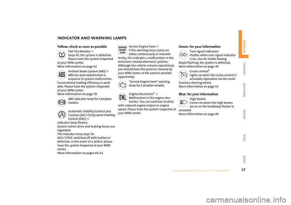
Yellow: check as soon as possible
Flat Tire Monitor
l
Stays lit: the system is defective.
Please have the system inspected
at your MINI center.
More information on page 62
Antilock Brake System (ABS)
l
ABS has been deactivated in
response to system malfunction.
Conventional braking efficiency is avail-
able. Please have the system inspected
at your MINI center.
More information on page 78
ABS indicator lamp for Canadian
models.
Automatic Stability Control plus
Traction (ASC+T)/Dynamic Stability
Control (DSC)
l
Indicator lamp flashes:
System active: drive and braking forces are
regulated.
The indicator lamp stays lit:
ASC+T/DSC switched off with button or
defective. In the event of a defect: please
have the system inspected at your MINI
center.
More information on pages 60, 61
Service Engine Soon
l
If the warning lamp comes on
either continuously or intermit-
tently, this indicates a malfunction in the
emissions-related electronic systems.
Although the vehicle remains operational,
you should have the systems checked by
your MINI center at the earliest possible
opportunity.
"Service Engine Soon" warning
lamp for Canadian models
.
Engine electronics
*
l
Malfunction in the engine elec-
tronics. You can continue to drive
with reduced engine output or engine
speed. Please have the system inspected at
your MINI center.
Green: for your information
Turn signal indicators
Flashes when turn signal indicator
is on, also for trailer towing.
Rapid flashing: the system is defective.
More information on page 49
Cruise control
*
Lights up when the cruise control is
activated. Operation via the multi-
function steering wheel.
More information on page 53
Blue: for your information
High beams
Comes on when the high beams
are on or the headlamp flasher is
actuated.
More information on page 49
Page 24 of 140

22
KEYS
Depending on the equipment fitted, your
MINI has up to three key variations:
1 Master key with remote control and
battery
If the battery is discharged, please
consult your MINI center. Battery
changing, see next column.
<
2 Door and ignition key
This key can only be used to open the
doors mechanically
3 Spare key for storage in a safe place, such
as in your wallet. This key is not intended
for constant use
Changing battery
Replace if it is no longer possible to unlock
the vehicle via the remote control.
Only use a battery of the type speci-
fied on the battery (CR 2032) and
make absolutely sure that it is fitted in the
correct position.
<
1. Apply a screwdriver at the recess
2. Use the screwdriver to lever out the
cover.
Return used batteries to a recycling
point or your MINI center.
<
Initializing the master key with remote
control
When you activate a master key with
remote control (replacement, additional
key or after a battery change), it must be
initialized.
This initialization can be performed in two
ways:
Press button 1 or button 2, see page 24,
four times in succession
or
if the vehicle is unlocked:
1. Switch the ignition on briefly (position 2)
and then off
2. Within 10 seconds, press button 1 and
button 2, see page 24, in succession.
In the event of a system malfunction,
please contact your MINI center. You
can also obtain replacement keys and
batteries there.
<
Page 29 of 140

27
OVERVIEW REPAIRS OPERATIONCONTROLS DATA INDEX
TAILGATE Opening from outsidePress the button in the handle.
The tailgate opens slightly.
Opening with the remote control, see
page 24.
Manual operationIn the event of an electrical malfunction,
you can also operate the tailgate manually.
3. Fold the rear seat bench upwards
4. Pull the ring.
The tailgate is unlocked.
ClosingThe handle recesses in the interior trim
panel of the tailgate make it easier to pull
the lid down.
To avoid injuries, be sure that the
travel path of the tailgate is clear
when it is closed, as with all closing proce-
dures.
Operate the vehicle only when the tailgate
is closed. Otherwise, exhaust fumes could
penetrate the interior of the vehicle.
Should it be absolutely necessary to
operate the vehicle with the tailgate open:
1. Close all windows. Shut the sliding/tilt
sunroof
2. Sharply increase the air supply for the air
conditioning or automatic climate
control, see pages 64 and/or 67.<
Page 33 of 140

31
OVERVIEW REPAIRS OPERATIONCONTROLS DATA INDEX
CORRECT SITTING POSTURE SEAT ADJUSTMENTThe ideal seating position can make a vital
contribution to relaxed, fatigue-free
driving. The correct seating position also
works together with the safety belts and
airbags to provide occupants with
maximum levels of passive safety in an
accident. To ensure that the safety systems
operate with optimal efficiency, we
strongly urge you to observe the instruc-
tions contained in the following section.
For supplementary information on trans-
porting children, refer to page 38. Sitting correctly with airbags
Always maintain an adequate
distance between yourself and all of
the airbags. Always hold the steering wheel
by the rim with the hands at the 9 and
3 o'clock positions to keep any chance of
injury to hands or arms to an absolute
minimum, should the airbag be deployed.
No one and nothing is to come between the
airbags and the seat occupant.
Never use the front passenger airbag cover
as a storage surface for objects of any kind,
or as a support for legs or feet, as this will
increase the risk of injury in a collision severe
enough in which the airbag will deploy.<
For airbag locations and additional infor-
mation on airbags, refer to page 37.
Safe with safety belts
Never allow more than one person to
wear a single safety belt. Never allow
infants or small children to ride in a
passenger's lap. Avoid twisting the belt
while routing it firmly across the hips and
shoulder, wear it as snugly against your
body as possible. Do not allow the belt to
rest against hard or fragile objects. Do not
route the belt across your neck, or run it
across sharp edges. Be sure that the belt
does not become caught or jammed.
Avoid wearing bulky clothing that prevents
the belt from fitting properly, and pull on
the belt periodically to retension it over
your shoulders. In the event of a frontal
impact, a loose lap belt could slide over the
hips, leading to abdominal injury. In addi-
tion, the safety belt's restraint effective-
ness is reduced if the belt is worn loosely.
Expectant mothers should always wear
their safety belts, taking care to position
the lap belt against the lower hips, where it
will not exert pressure against the abdom-
inal area.<
For information on using the safety belts,
refer to page 35.
Important adjustment information
Never try to adjust your seat while
operating the vehicle. The seat could
respond with an unexpected movement,
and the ensuing loss of vehicle control
could lead to an accident.
Never ride with the backrest reclined to an
extreme horizontal angle (especially impor-
tant for front passengers to remember).
Keep the backrest relatively upright to
minimize the risk of sliding under the
safety belt and sustaining injury in an acci-
dent.<
Adjusting the seats, see next page.
Page 63 of 140

61
OVERVIEW REPAIRS OPERATIONCONTROLS DATA INDEX
DYNAMIC STABILITY CONTROL (DSC)
*
The concept
This system maintains driving stability
even in critical driving situations.
The system optimizes vehicle stability
during acceleration and when starting
from a full stop, as well as optimizing trac-
tion. In addition, it recognizes unstable
vehicle conditions, such as under- or over-
steering, and, as far as is possible within
the laws of physics, helps keeping the
vehicle on a steady course by reducing the
rpms and brake applications to the indi-
vidual wheels.
The DSC is operational every time you start
the engine. DSC contains the functions
Antilock Brake System ABS/Electronic Brake
Force Distribution EBV/ASC+T.
The laws of physics cannot be
repealed, even with DSC. An appro-
priate driving style always remains the
responsibility of the driver. We therefore
urge you to avoid using the additional
safety margin of the system as an excuse
for taking risks.
Do not make any modifications to the DSC
system. Allow only authorized technicians
to perform service procedures on the
DSC.<
To switch off the DSCBriefly press the switch.
The indicator lamp stays lit.
When driving with snow chains, it may be
effective to switch off the DSC for a brief
period.
To maintain stability, always drive
with the DSC switched on whenever
possible.
Indicator lamp
The indicator lamp on the instru-
ment cluster will go out shortly
after the ignition has been
switched on, see pages 16, 17.
If the indicator lamp flashes:
DSC controls the drive and braking forces.
If the indicator lamp fails to go out
after the engine is started, or if it
comes on during normal driving and stays
on:
If the system is either defective or was
switched off with the button, then the
stabilizing applications described are no
longer available. The vehicle will remain
completely operational, however, without
DSC.
In the event of a malfunction, please see
your MINI center, see pages 16, 17.<
Page 64 of 140

62
FLAT TIRE MONITORThe conceptThe tire inflation pressure is determined
from the signals of the ABS sensors.
The system provides an alert whenever the
tire inflation pressure drops below the
pressure in any other tire. RequirementSo that the system can "familiarize" itself
with the correct inflation pressure, please
do the following:
1. Check the tire inflation pressure in all
tires
2. Compare them with the inflation pres-
sure table, see page 81, and adjust the
pressures if necessary
3. Initialize the system.
Check the tire inflation pressure
regularly and correct it if necessary,
see page 80.<
Flat tire
The indicator lamp in the instru-
ment cluster informs you by
flashing when the tire inflation
pressure of a tire drops in relation to any
other tire. In addition, an acoustic signal is
sounded.
>Vehicles with safety (run-flat) tires, see
notes on pages 110, 80, 84
>Vehicles with normal tires, see notes on
pages 106, 80.
The Flat Tire Monitor cannot alert you
to severe and sudden tire damage
caused by external factors. Another factor
which the Flat Tire Monitor does not recog-
nize is the balanced and very gradual pres-
sure loss that takes place in all tires over an
extended period of time.<
MalfunctionsAs long as there is still a malfunction, the
yellow indicator lamp on the instrument
cluster will stay lit up.
The indicator lamp also lights up in the
event of a system malfunction.
Please contact your MINI center in these
cases.
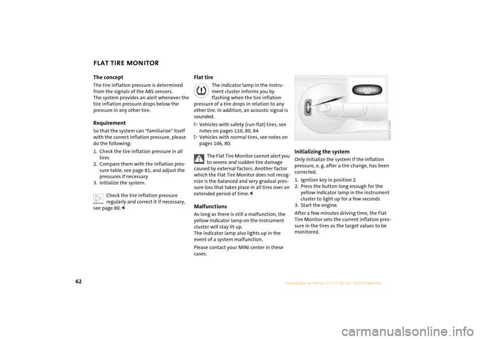
Initializing the systemOnly initialize the system if the inflation
pressure, e. g. after a tire change, has been
corrected.
1. Ignition key in position 2
2. Press the button long enough for the
yellow indicator lamp in the instrument
cluster to light up for a few seconds
3. Start the engine.
After a few minutes driving time, the Flat
Tire Monitor sets the current inflation pres-
sure in the tires as the target values to be
monitored.
Page 78 of 140

76
BREAK-IN PROCEDURES GENERAL DRIVING NOTES To ensure that your vehicle provides
maximum economy throughout a long
service life, we request that you comply
with the following information: EngineUp to 1,200 miles (2,000 km):
Attempt to constantly vary both vehicle
and engine speed during these initial miles
while remembering to avoid engine speeds
in excess of 4,500 rpm and/or vehicle
speeds of over 95 mph (150 km/h).
Absolutely avoid using the full-throttle or
kickdown position for the accelerator.
Once you have driven 1,200 miles
(2,000 km), both the engine and vehicle
speed can be gradually increased.
You should also comply with these break-in
procedures if the engine has to be replaced
at a later point.
TiresDue to technical factors associated with
their manufacture, tires do not achieve
their full traction potential until after an
initial break-in period. We therefore ask
you to drive with extra care during the first
200 miles (300 km).Brake systemApprox. 300 miles (500 km) must be driven
before the brake pads and rotors achieve
the optimum pad-surface and wear
patterns required for trouble-free opera-
tion and an extended service life.ClutchRoughly 300 miles (500 km) must be driven
before the clutch starts to operate at
optimum efficiency. Remember to engage
the clutch carefully during this initial
period.
Parking the vehicleCondensation forms in the air conditioner
system during operation, and then exits
under the vehicle. Traces of condensed
water under the vehicle are therefore
normal.Brakes
Do not rest your foot on the brake
pedal while driving. Even light but
consistent pedal pressure can lead to high
temperatures, brake wear and possibly
even brake failure.<
Hydroplaning
When driving on wet or slushy roads,
reduce road speed. If you do not, a
wedge of water can form between tires and
road surface. This phenomenon is charac-
terized by a partial or complete loss of
contact between the tires and the road
surface. The ultimate results are loss of
steering and braking control.<
Page 80 of 140

78
FUEL SPECIFICATIONS ANTILOCK BRAKE SYSTEM (ABS)The engine uses lead-free gasoline only.
Required fuel:
>Premium Unleaded Gasoline,
min. 91 AKI.
AKI = Anti Knock Index.
Do not use leaded fuels. The use of
leaded fuels will cause permanent
damage to the emissions-control system's
oxygen sensor and the catalytic
converter.<
The concept The ABS keeps the wheels from locking
while braking, thereby enhancing active
driving safety.
ABS also includes Electronic Brake Force
Distribution (EBV).Braking with ABSTo achieve optimal performance from ABS
when reacting to critical situations you
should apply maximum pressure to the
brake pedal ("panic stop").
Since the vehicle maintains steering
responsiveness, you can nevertheless avoid
possible obstacles with a minimum of
steering effort.
Pulsation of the brake pedal in conjunction
with the sound of hydraulic regulation indi-
cates to you that you are driving at the limit
and reminds you to readapt your vehicle's
speed to road surface conditions.