key MINI Hardtop 2 Door 2004 User Guide
[x] Cancel search | Manufacturer: MINI, Model Year: 2004, Model line: Hardtop 2 Door, Model: MINI Hardtop 2 Door 2004Pages: 152, PDF Size: 1.41 MB
Page 38 of 152
36
STEERING WHEEL MIRRORS
Do not adjust the steering wheel
while the vehicle is moving; other-
wise unexpected movement could increase
the risk of accident.<
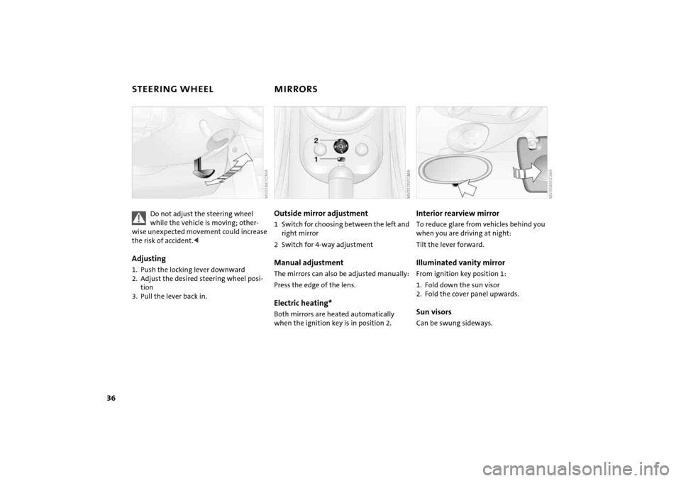
Adjusting1. Push the locking lever downward
2. Adjust the desired steering wheel posi-
tion
3. Pull the lever back in.
Outside mirror adjustment1Switch for choosing between the left and
right mirror
2Switch for 4-way adjustmentManual adjustmentThe mirrors can also be adjusted manually:
Press the edge of the lens.Electric heating*Both mirrors are heated automatically
when the ignition key is in position 2.
Interior rearview mirror To reduce glare from vehicles behind you
when you are driving at night:
Tilt the lever forward.Illuminated vanity mirrorFrom ignition key position 1:
1. Fold down the sun visor
2. Fold the cover panel upwards.Sun visorsCan be swung sideways.
Page 43 of 152
41
OVERVIEW REPAIRS OPERATIONCONTROLS DATA INDEX
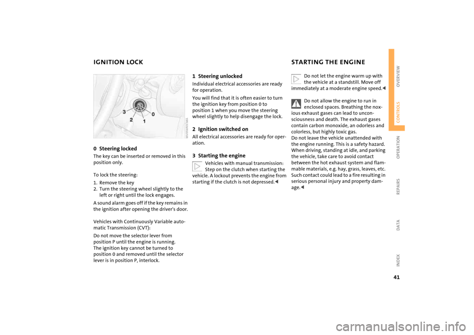
IGNITION LOCK STARTING THE ENGINE0Steering locked The key can be inserted or removed in this
position only.
To lock the steering:
1. Remove the key
2. Turn the steering wheel slightly to the
left or right until the lock engages.
A sound alarm goes off if the key remains in
the ignition after opening the driver's door.
Vehicles with Continuously Variable auto-
matic Transmission (CVT):
Do not move the selector lever from
position P until the engine is running.
The ignition key cannot be turned to
position 0 and removed until the selector
lever is in position P, interlock.
1Steering unlockedIndividual electrical accessories are ready
for operation.
You will find that it is often easier to turn
the ignition key from position 0 to
position 1 when you move the steering
wheel slightly to help disengage the lock.2Ignition switched onAll electrical accessories are ready for oper-
ation.3Starting the engine
Vehicles with manual transmission:
Step on the clutch when starting the
vehicle. A lockout prevents the engine from
starting if the clutch is not depressed.<
Do not let the engine warm up with
the vehicle at a standstill. Move off
immediately at a moderate engine speed.<
Do not allow the engine to run in
enclosed spaces. Breathing the nox-
ious exhaust gases can lead to uncon-
sciousness and death. The exhaust gases
contain carbon monoxide, an odorless and
colorless, but highly toxic gas.
Do not leave the vehicle unattended with
the engine running. This is a safety hazard.
When driving, standing at idle, and parking
the vehicle, take care to avoid contact
between the hot exhaust system and flam-
mable materials, e.g. hay, grass, leaves, etc.
Such contact could lead to a fire resulting in
serious personal injury and property dam-
age.<
Page 44 of 152
42
STARTING THE ENGINEStartingWhen starting the engine, do not press the
accelerator pedal.
Do not actuate the starter for too
short a time. Do not turn it for more
than approx. 20 seconds. Release the igni-
tion key immediately when the engine
starts.
Extended starting attempts, characterized
by excessively frequent or long periods
with the starter engaged, can lead to dam-
age in the catalytic converter.<
If the engine does not start on the first
attempt, for instance if the engine is very
hot or cold:
When starting the engine, press the gas
pedal down halfway.
When first starting the engine at very low
temperatures, from +57 / –156:
When starting the engine, press the gas
pedal down halfway. For the initial start
attempt, allow the starter to remain
engaged somewhat longer, approx.
10 seconds.
Manual transmission1. Engage the parking brake
2. Put the manual gearshift lever in neutral
3. Press the clutch pedal
4. Start the engine.
Move the gearshift lever to neutral
position and engage the parking
brake before leaving your vehicle with the
engine running.
Do not leave the vehicle unattended with
the engine running. This is a safety haz-
ard.<
Continuously Variable automatic
Transmission (CVT)1. Press the footbrake
2. Put the selector lever in position P or N
3. Start the engine.
Move the selector lever to position P
and engage the parking brake before
leaving your vehicle with the engine run-
ning.
Do not leave the vehicle unattended with
the engine running. This is a safety haz-
ard.<
Page 45 of 152
43
OVERVIEW REPAIRS OPERATIONCONTROLS DATA INDEX
SWITCHING OFF THE ENGINE PARKING BRAKE
You should never remove the ignition
key when the vehicle is in motion, as
the steering lock could engage.
When you leave the vehicle, always remove
the ignition key and engage the steering
lock.
When you park on downward slopes,
engage the parking brake.<
Manual transmissionTurn the ignition key to position 1 or 0.Continuously Variable automatic
Transmission (CVT)Engage selector lever position P, turn the
ignition key to position 1 or 0.
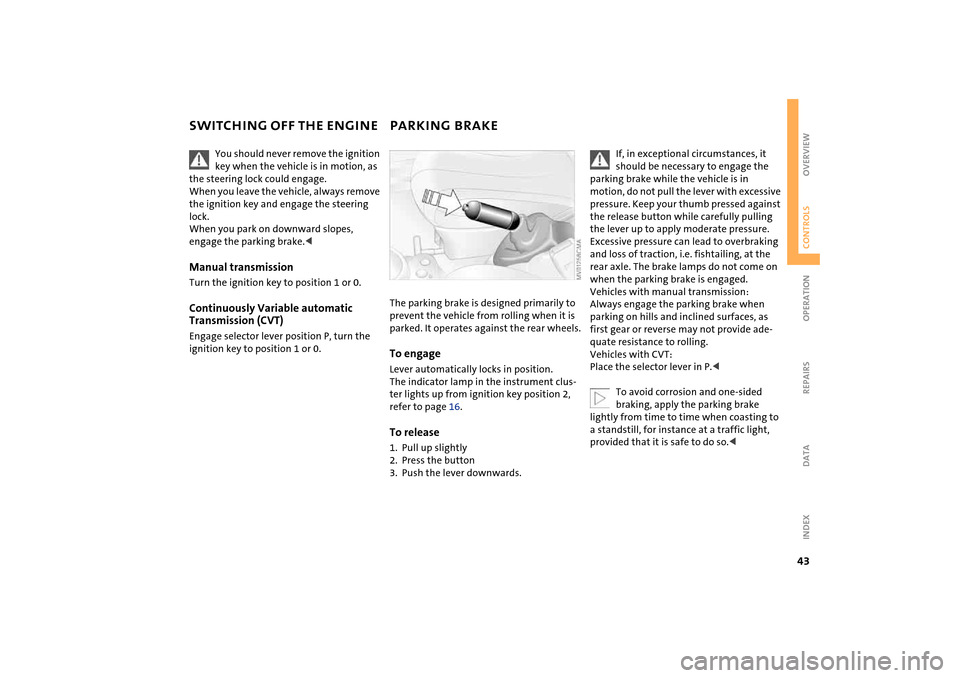
The parking brake is designed primarily to
prevent the vehicle from rolling when it is
parked. It operates against the rear wheels.To engageLever automatically locks in position.
The indicator lamp in the instrument clus-
ter lights up from ignition key position 2,
refer to page 16.To release1. Pull up slightly
2. Press the button
3. Push the lever downwards.
If, in exceptional circumstances, it
should be necessary to engage the
parking brake while the vehicle is in
motion, do not pull the lever with excessive
pressure. Keep your thumb pressed against
the release button while carefully pulling
the lever up to apply moderate pressure.
Excessive pressure can lead to overbraking
and loss of traction, i.e. fishtailing, at the
rear axle. The brake lamps do not come on
when the parking brake is engaged.
Vehicles with manual transmission:
Always engage the parking brake when
parking on hills and inclined surfaces, as
first gear or reverse may not provide ade-
quate resistance to rolling.
Vehicles with CVT:
Place the selector lever in P.<
To avoid corrosion and one-sided
braking, apply the parking brake
lightly from time to time when coasting to
a standstill, for instance at a traffic light,
provided that it is safe to do so.<
Page 46 of 152

44
MANUAL TRANSMISSION 6-speed transmission*
When changing gear in the 5th/6th
gear plane, press the gearshift lever
to the right to prevent inadvertently shift-
ing to a gear of the 3rd/4th gear plane.<
Reverse gearBefore selecting reverse gear, ensure the
vehicle is stationary; then, fully depress the
clutch pedal and pause briefly before mov-
ing the gearshift lever into position.
5-speed transmission:
Press the gearshift lever to the right and to
the back.
6-speed transmission:
Press the gearshift lever towards the left.
Thereby overcome the slight resistance and
press forward.
As you do this, the backup lamps will turn
on automatically when the ignition key is
in position 2.
Do not hold the vehicle in place on
slopes by slipping or 'riding' the
clutch. Use the parking brake instead.
Riding the clutch causes the clutch assem-
bly to wear out sooner.<
Page 50 of 152

48
PARKING LAMPS/LOW BEAMS Switching on the parking lamps Turn to the first position. The front, rear
and side vehicle lighting is switched on.
Parking light on one side, refer to following
column.Switching on the low beamsTurn to the second position. With the low
beams on and with the ignition switched
off, only the parking lamps will remain on.
'Follow me home' lampsIf you activate the headlamp flasher after
having switched off the engine and the
lights, the low beams will stay lit for a pre-
set period of time.
You can have this function set by
your MINI Dealer.
1. Turn the ignition key to position 0 or
remove the key
2. Switch on the low beams
3. Move the lever to the adequate turn sig-
nal indicator position.'Lights on' warningIf the lights have not been switched off and
the ignition key is in position 0, an acoustic
signal sounds for a few seconds when you
open the driver's door to remind you that
the lights have not been switched off.
Daytime driving lamps* If you desire, the light switch can be left in
position 2.
When the ignition is switched off, the car's
exterior lights go out.
The automatic headlamp range con-
trol for xenon lamps only operates
with the light switch in position 1 or 2.<
You can have the daytime driving
lamp function activated/deactivated
by your MINI Dealer.<
Page 53 of 152

51
OVERVIEW REPAIRS OPERATIONCONTROLS DATA INDEX
WASHER/WIPER SYSTEMwindshield wipers are automatically con-
trolled depending on the amount of mois-
ture, including snow, on the windshield.
To activate the rain sensor:
From ignition key position 1:
Lever in position 1.
The wipers move over the windshield once.
To deactivate the rain sensor:
Put lever in position 0.
Switch the rain sensor off when pass-
ing through an automatic car wash.
Failure to do so could result in damage
caused by undesired wiper activation.
ing.
You can have this function activated/
deactivated by your MINI Dealer.
speed.
You can have this function activated/
deactivated by your MINI Dealer.<
Cleaning windshield and headlamps* The system sprays washer fluid against the
windshield. The wipers are automatically
activated for a brief period.
When the vehicle lighting is on, the head-
lamps are also cleaned at appropriate inter-
vals.
Do not use the washers if there is any
danger that the fluid will freeze on
the windshield. For this reason, use an anti-
freeze agent, refer to page 98
Do not use the washers when the reservoir
is empty, since this could cause damage to
the washing pump.
position 2.
Rear window wiper6Intermittent operation:
Turn the cap to position 6.
The rear window wiper moves across the
window a number of times before
switching to intermittent operationCleaning rear window7Intermittent operation:
Turn the cap to position 7 and hold in
place
8In lever position 0:
Turn the cap to position 8 and hold in
place
Page 54 of 152

52
CRUISE CONTROL
*
On the multifunction steering wheel
and sports steering wheel
The vehicle maintains and stores any
desired speed when driving above approx.
20 mph / 30 km/h. Vehicles with manual
transmission must be driving in 3rd gear or
higher.
Do not use cruise control on twisting
roads, when high traffic density pre-
vents driving at a constant speed, or when
the road surface does not permit driving at
a constant speed, e.g. due to snow, rain, ice,
loose surfaces.<
To activate via the multifunction
steering wheelFrom ignition key position 1:
Press button 2.
The indicator lamp in the instrument clus-
ter lights up.
Cruise control is active.To activate via the sports steering
wheel1. Start the engine
2. Press button 2.
The indicator lamp in the instrument clus-
ter lights up.
Cruise control is active.
To deactivate Press button 2 repeatedly until the indica-
tor lamp goes out.
The cruise control is deactivated when the
ignition key is turned to position 0.
The stored speed is cleared.
Page 56 of 152
54
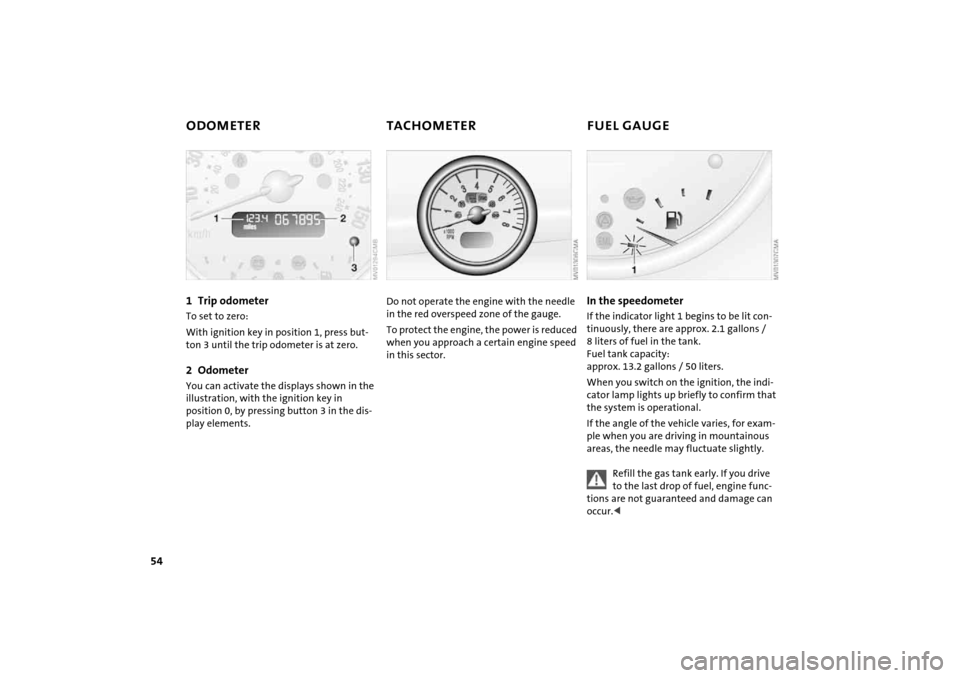
ODOMETER TACHOMETER FUEL GAUGE 1Trip odometer To set to zero:
With ignition key in position 1, press but-
ton 3 until the trip odometer is at zero.2OdometerYou can activate the displays shown in the
illustration, with the ignition key in
position 0, by pressing button 3 in the dis-
play elements.
Do not operate the engine with the needle
in the red overspeed zone of the gauge.
To protect the engine, the power is reduced
when you approach a certain engine speed
in this sector.
In the speedometer If the indicator light 1 begins to be lit con-
tinuously, there are approx. 2.1 gallons /
8 liters of fuel in the tank.
Fuel tank capacity:
approx. 13.2 gallons / 50 liters.
When you switch on the ignition, the indi-
cator lamp lights up briefly to confirm that
the system is operational.
If the angle of the vehicle varies, for exam-
ple when you are driving in mountainous
areas, the needle may fluctuate slightly.
Refill the gas tank early. If you drive
to the last drop of fuel, engine func-
tions are not guaranteed and damage can
occur.<
Page 58 of 152
56
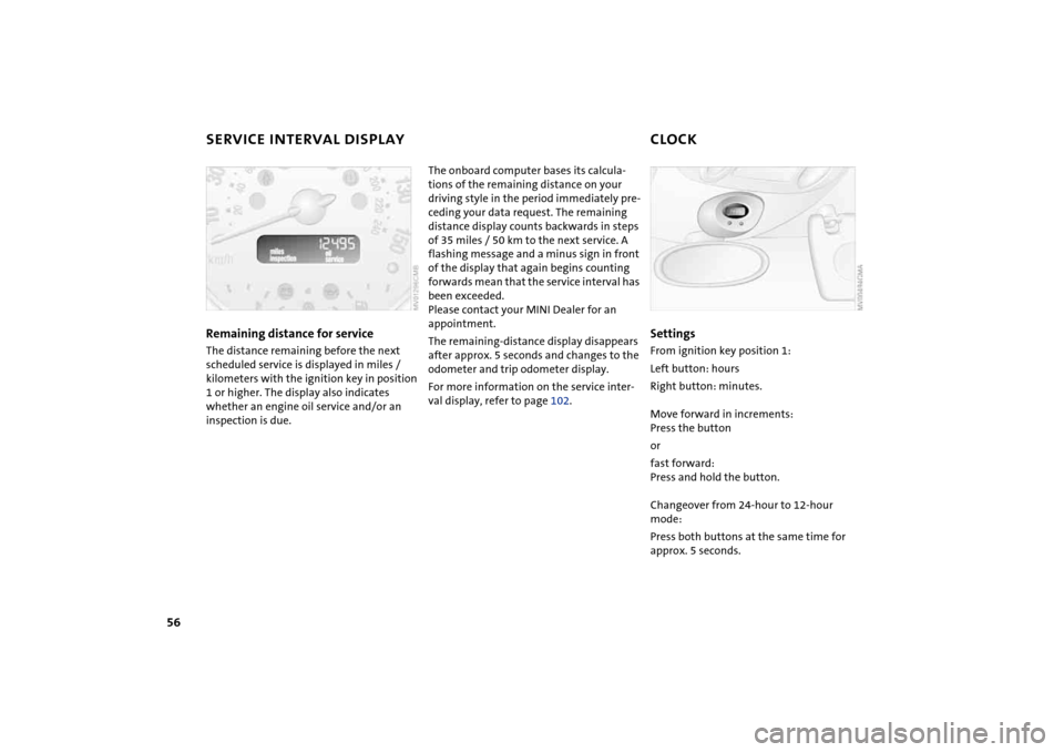
SERVICE INTERVAL DISPLAY CLOCKRemaining distance for serviceThe distance remaining before the next
scheduled service is displayed in miles /
kilometers with the ignition key in position
1 or higher. The display also indicates
whether an engine oil service and/or an
inspection is due.
The onboard computer bases its calcula-
tions of the remaining distance on your
driving style in the period immediately pre-
ceding your data request. The remaining
distance display counts backwards in steps
of 35 miles / 50 km to the next service. A
flashing message and a minus sign in front
of the display that again begins counting
forwards mean that the service interval has
been exceeded.
Please contact your MINI Dealer for an
appointment.
The remaining-distance display disappears
after approx. 5 seconds and changes to the
odometer and trip odometer display.
For more information on the service inter-
val display, refer to page 102.
SettingsFrom ignition key position 1:
Left button: hours
Right button: minutes.
Move forward in increments:
Press the button
or
fast forward:
Press and hold the button.
Changeover from 24-hour to 12-hour
mode:
Press both buttons at the same time for
approx. 5 seconds.