ESP MINI Hardtop 2 Door 2004 Owner's Manual
[x] Cancel search | Manufacturer: MINI, Model Year: 2004, Model line: Hardtop 2 Door, Model: MINI Hardtop 2 Door 2004Pages: 152, PDF Size: 1.41 MB
Page 9 of 152
7
OVERVIEW REPAIRS OPERATION CONTROLS DATA INDEX
Editorial notice
The manufacturer pursues a policy of con-
tinuous, ongoing development that is con-
ceived to ensure that the MINI continues to
embody the highest quality and safety
standards combined with advanced, state-
of-the-art technology. For this reason, the
features described in this Owner's Manual
could differ from those on your vehicle. Nor
can errors and omissions be entirely ruled
out.
You are therefore asked to appreciate that
no claims can be entertained on the basis
of the data, illustrations or descriptions in
this Owner's Manual.
For your own safety
Fuels
Use unleaded gasoline only. Fuels
containing up to and including 10 %
ethanol or other oxygenates with up to
2.8 % oxygen by weight, i.e. 15 % MTBE or
3% methanol plus an equivalent amount of
co-solvent, will not void the applicable war-
ranties with respect to defects in materials
or workmanship. Field experience has indi-
cated significant differences in fuel quality,
i.e. volatility, composition, additives, etc.,
among gasolines offered for sale in the
United States and Canada. The use of poor-
quality fuels may result in driveability,
starting and stalling problems, especially
under certain environmental conditions
such as high ambient temperature and
high altitude.
Should you encounter driveability prob-
lems which you suspect could be related to
the fuel you are using, we recommend that
you respond by switching to a recognized
high-quality brand.
Failure to comply with these recommenda-
tions may result in unscheduled mainte-
nance.
Obey pertinent safety rules when you are
handling gasoline.
<
Maintenance and repair
Advanced technology, e.g. the use of
modern materials and high-perfor-
mance electronics, requires specially
adapted maintenance and repair methods.
Therefore, only have corresponding work
on your MINI carried out by a MINI Dealer
or a workshop that works according to
MINI repair procedures with correspond-
ingly trained personnel. If work is carried
out improperly there is a danger of conse-
quential damage and the related safety
risks.
<
NOTES
Page 17 of 152
15
OVERVIEW REPAIRS OPERATION CONTROLS DATA INDEX
INDICATOR AND WARNING LAMPS
Technology that monitors itself
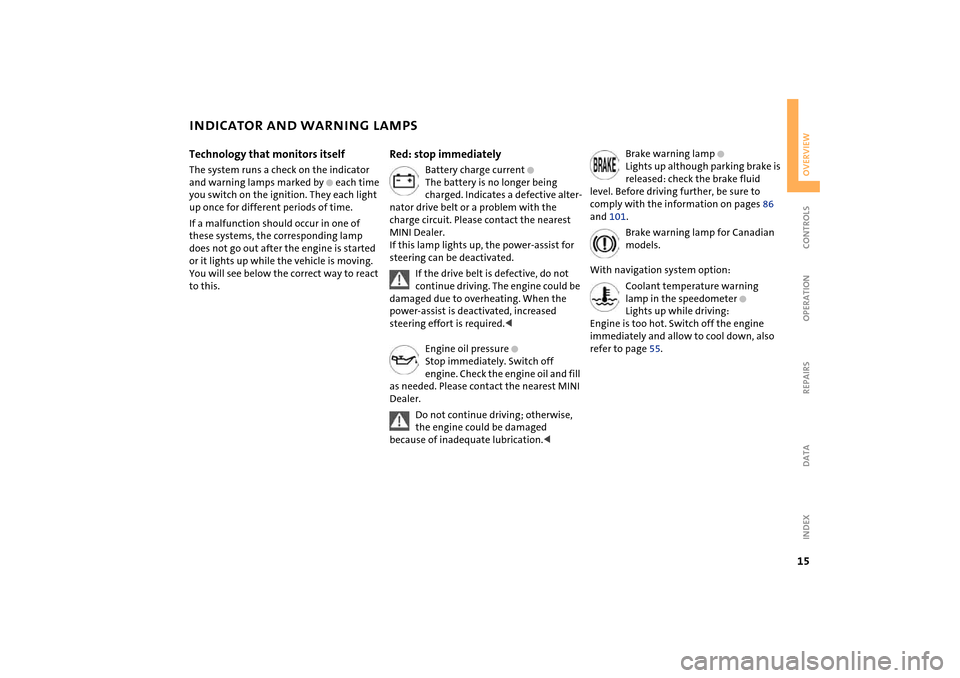
The system runs a check on the indicator
and warning lamps marked by
+
each time
you switch on the ignition. They each light
up once for different periods of time.
If a malfunction should occur in one of
these systems, the corresponding lamp
does not go out after the engine is started
or it lights up while the vehicle is moving.
You will see below the correct way to react
to this.
Red: stop immediately
Battery charge current
+
The battery is no longer being
charged. Indicates a defective alter-
nator drive belt or a problem with the
charge circuit. Please contact the nearest
MINI Dealer.
If this lamp lights up, the power-assist for
steering can be deactivated.
If the drive belt is defective, do not
continue driving. The engine could be
damaged due to overheating. When the
power-assist is deactivated, increased
steering effort is required.
<
Engine oil pressure
+
Stop immediately. Switch off
engine. Check the engine oil and fill
as needed. Please contact the nearest MINI
Dealer.
Do not continue driving; otherwise,
the engine could be damaged
because of inadequate lubrication.
<
Brake warning lamp
+
Lights up although parking brake is
released: check the brake fluid
level. Before driving further, be sure to
comply with the information on pages 86
and 101.
Brake warning lamp for Canadian
models.
With navigation system option:
Coolant temperature warning
lamp in the speedometer
+
Lights up while driving:
Engine is too hot. Switch off the engine
immediately and allow to cool down, also
refer to page 55.
Page 19 of 152
17
OVERVIEW REPAIRS OPERATION CONTROLS DATA INDEX
INDICATOR AND WARNING LAMPS
Yellow: check as soon as possible
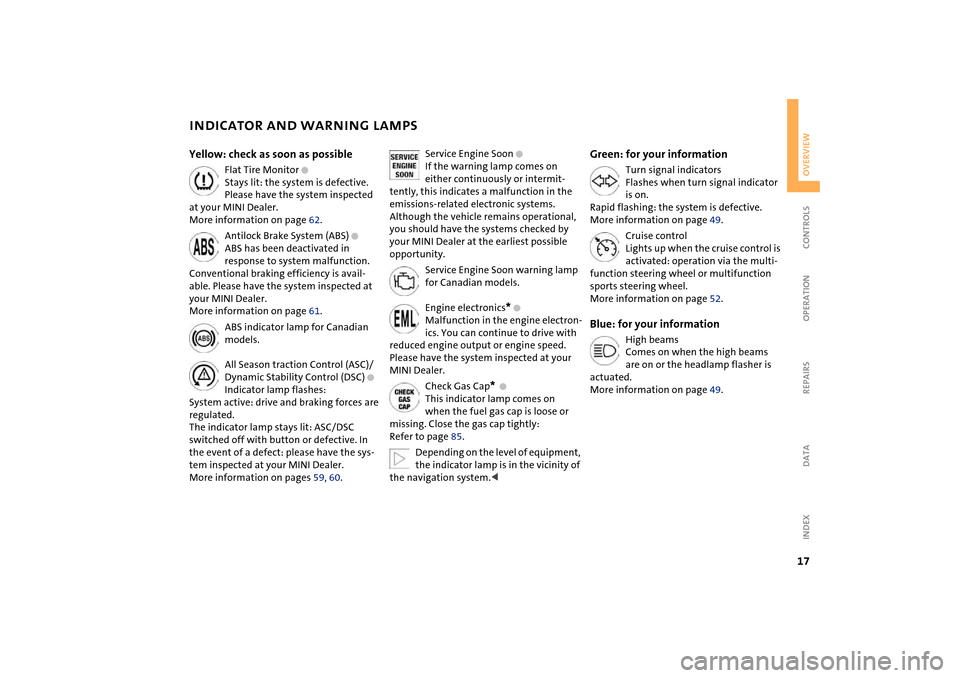
Flat Tire Monitor
+
Stays lit: the system is defective.
Please have the system inspected
at your MINI Dealer.
More information on page 62.
Antilock Brake System (ABS)
+
ABS has been deactivated in
response to system malfunction.
Conventional braking efficiency is avail-
able. Please have the system inspected at
your MINI Dealer.
More information on page 61.
ABS indicator lamp for Canadian
models.
All Season traction Control (ASC)/
Dynamic Stability Control (DSC)
+
Indicator lamp flashes:
System active: drive and braking forces are
regulated.
The indicator lamp stays lit: ASC/DSC
switched off with button or defective. In
the event of a defect: please have the sys-
tem inspected at your MINI Dealer.
More information on pages 59, 60.
Service Engine Soon
+
If the warning lamp comes on
either continuously or intermit-
tently, this indicates a malfunction in the
emissions-related electronic systems.
Although the vehicle remains operational,
you should have the systems checked by
your MINI Dealer at the earliest possible
opportunity.
Service Engine Soon warning lamp
for Canadian models.
Engine electronics
*
+
Malfunction in the engine electron-
ics. You can continue to drive with
reduced engine output or engine speed.
Please have the system inspected at your
MINI Dealer.
Check Gas Cap
*
+
This indicator lamp comes on
when the fuel gas cap is loose or
missing. Close the gas cap tightly:
Refer to page 85.
Depending on the level of equipment,
the indicator lamp is in the vicinity of
the navigation system.
<
Green: for your information
Turn signal indicators
Flashes when turn signal indicator
is on.
Rapid flashing: the system is defective.
More information on page 49.
Cruise control
Lights up when the cruise control is
activated: operation via the multi-
function steering wheel or multifunction
sports steering wheel.
More information on page 52.
Blue: for your information
High beams
Comes on when the high beams
are on or the headlamp flasher is
actuated.
More information on page 49.
Page 32 of 152
30
GLASS SUNROOF, ELECTRIC
*
ROLLER SUN BLIND
*
Pinch protection
If, while closing, the glass sunroof encoun-
ters resistance within roughly the last 8 in /
20 cm, the closing procedure is interrupted
and the roof reopens.
Despite the pinch protection, be
extremely careful that the travel path
of the sunroof is not obstructed whenever
it is closed. Otherwise, it is not guaranteed
that the closing procedure will be inter-
rupted, for instance if the obstructions
offer very little resistance.
You can disable the pinch protection by
pressing the switch past the pressure point
and holding it.<
When closing the sunroof from the
raised position, ensure that the travel
path of the sunroof is not obstructed since
the pinch protection is not active in this
position.<
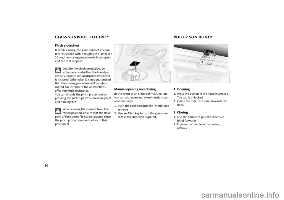
Manual opening and closing In the event of an electrical malfunction,
you can also open and close the glass sun-
roof manually:
1. Push the clock towards the interior and
remove
2. Use an Allen key to turn the glass sun-
roof in the direction required.
1Opening1. Press the button in the handle, arrow 1
The cap is unlocked
2. Guide the roller sun blind towards the
back.2Closing1. Use the handle to pull the roller sun
blind forwards
2. Engage the handle in the device,
arrow 2.
Page 34 of 152
32
SEAT ADJUSTMENTImportant adjustment information
Never try to adjust your seat while
operating the vehicle. The seat could
respond with an unexpected movement,
and the ensuing loss of vehicle control
could lead to an accident.
While driving, do not recline the backrest
too far toward the rear. This especially
applies to the front passenger side. If you
do so, there is a risk that you will slide
under the safety belt in an accident, thus
reducing the protection provided by the
safety belt.<
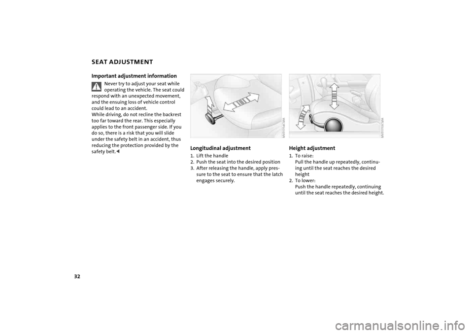
Longitudinal adjustment1. Lift the handle
2. Push the seat into the desired position
3. After releasing the handle, apply pres-
sure to the seat to ensure that the latch
engages securely.
Height adjustment 1. To raise:
Pull the handle up repeatedly, continu-
ing until the seat reaches the desired
height
2. To lower:
Push the handle repeatedly, continuing
until the seat reaches the desired height.
Page 42 of 152
40
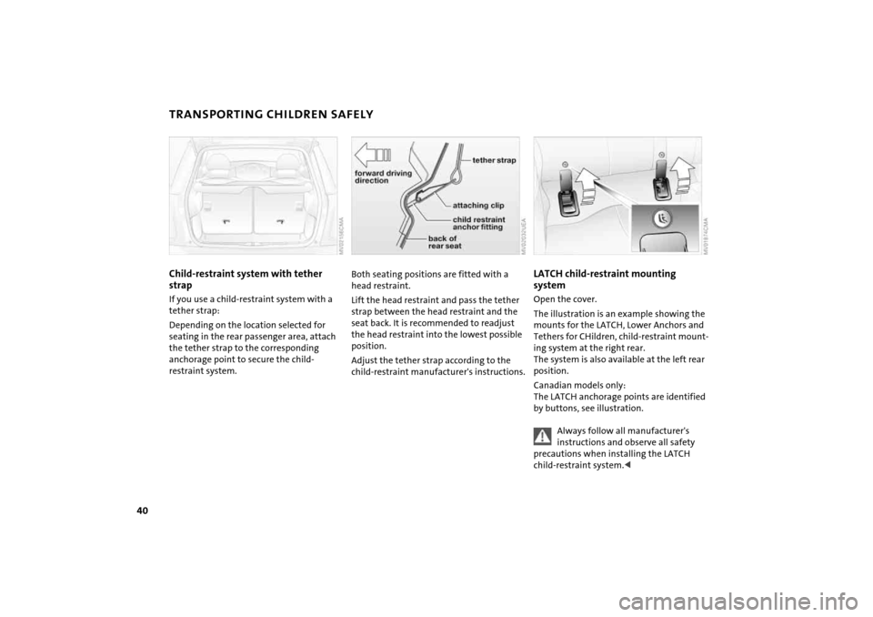
TRANSPORTING CHILDREN SAFELYChild-restraint system with tether
strapIf you use a child-restraint system with a
tether strap:
Depending on the location selected for
seating in the rear passenger area, attach
the tether strap to the corresponding
anchorage point to secure the child-
restraint system.
Both seating positions are fitted with a
head restraint.
Lift the head restraint and pass the tether
strap between the head restraint and the
seat back. It is recommended to readjust
the head restraint into the lowest possible
position.
Adjust the tether strap according to the
child-restraint manufacturer's instructions.
LATCH child-restraint mounting
system Open the cover.
The illustration is an example showing the
mounts for the LATCH, Lower Anchors and
Tethers for CHildren, child-restraint mount-
ing system at the right rear.
The system is also available at the left rear
position.
Canadian models only:
The LATCH anchorage points are identified
by buttons, see illustration.
Always follow all manufacturer's
instructions and observe all safety
precautions when installing the LATCH
child-restraint system.<
Page 61 of 152
59
OVERVIEW REPAIRS OPERATIONCONTROLS DATA INDEX
ALL SEASON TRACTION CONTROL (ASC)
*
The concept
This system optimizes driving stability and
traction, especially when just starting off,
when accelerating or when cornering.
ASC recognizes the danger present in trac-
tion loss and will increase driving stability
and traction by reducing the engine's out-
put and, if necessary, by applying the
brakes to the front wheels.
ASC is operational each time you start the
engine. It contains the following functions:
>Antilock Brake System (ABS)
>Cornering Brake Control (CBC)
>Electronic Brake Force Distribution (EBD).
The laws of physics cannot be
repealed, even with ASC. An appropri-
ate driving style always remains the
responsibility of the driver. Avoid using the
additional safety margin provided by the
system as an excuse for taking unnecessary
risks.
Do not make any modifications to the ASC
system. Allow only authorized technicians
to perform service procedures on the
ASC.<
Indicator lamp
The indicator lamp in the display
elements will go out shortly after
the ignition has been switched on,
refer to pages 16, 17.
If the indicator lamp flashes:
ASC controls the drive and braking forces.
If the indicator lamp fails to go out after
the engine is started, or if it comes on dur-
ing normal driving and stays on:
The system is defective or was turned off
using the button.
The described stabilizing operations are no
longer available.
You can, however, drive the vehicle nor-
mally without ASC.
In the event of a malfunction, please see
your MINI Dealer, refer to pages 16, 17.
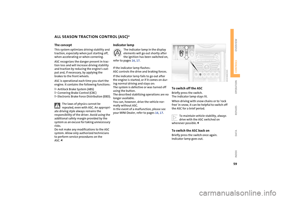
To switch off the ASCBriefly press the switch.
The indicator lamp stays lit.
When driving with snow chains or to 'rock
free' in snow, it can be helpful to switch off
the ASC for a brief period.
To maintain vehicle stability, always
drive with the ASC switched on
whenever possible.
Page 62 of 152
60
DYNAMIC STABILITY CONTROL (DSC)
*
The concept
This system optimizes driving stability and
traction, especially when just starting off,
when accelerating or when cornering. It
also maintains driving stability even in criti-
cal driving situations.
DSC recognizes unstable vehicle conditions,
such as understeering or oversteering, and,
as far as is possible within the laws of phys-
ics, helps keep the vehicle on a steady
course by reducing the rpms and by brake
applications to the individual wheels.
The DSC is operational every time you start
the engine. It contains the following func-
tions:
>All Season traction Control (ASC)
>Antilock Brake System (ABS)
>Cornering Brake Control (CBC)
>Electronic Brake Force Distribution (EBD).
The laws of physics cannot be
repealed, even with DSC. An appropri-
ate driving style always remains the respon-
sibility of the driver. Avoid using the addi-
tional safety margin provided by the system
as an excuse for taking unnecessary risks.
Do not make any modifications to the DSC
system. Allow only authorized technicians to
perform service procedures on the DSC.<
Indicator lamp
The indicator lamp in the display
elements will go out shortly after
the ignition has been switched on,
refer to pages 16, 17.
If the indicator lamp flashes:
DSC controls the drive and braking forces.
If the indicator lamp fails to go out after
the engine is started, or if it comes on dur-
ing normal driving and stays on:
The system is defective or was turned off
using the button.
The described stabilizing operations are no
longer available.
The vehicle will remain completely opera-
tional, however, without DSC.
In the event of a malfunction, please see
your MINI Dealer, refer to pages 16, 17.
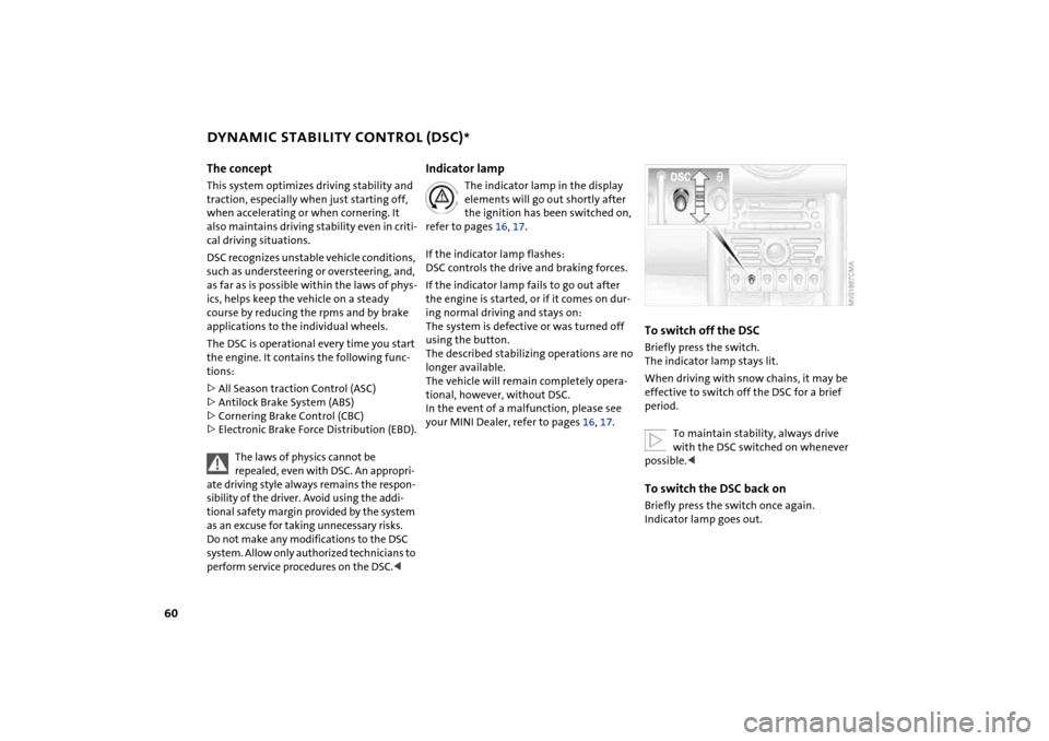
To switch off the DSCBriefly press the switch.
The indicator lamp stays lit.
When driving with snow chains, it may be
effective to switch off the DSC for a brief
period.
To maintain stability, always drive
with the DSC switched on whenever
possible.
Page 63 of 152
61
OVERVIEW REPAIRS OPERATIONCONTROLS DATA INDEX
ANTILOCK BRAKE SYSTEM (ABS) The concept The ABS keeps the wheels from locking
while braking, thereby enhancing active
driving safety.
ABS also includes Electronic Brake Force
Distribution (EBD).Braking with ABSTo achieve optimal performance from ABS
when reacting to critical situations, you
should apply maximum pressure to the
brake pedal – panic stop.
Since the vehicle remains maneuverable,
you can still go around any obstacles with
the smallest possible steering movements.
Pulsation of the brake pedal in conjunction
with the sound of hydraulic regulation indi-
cates to you that you are driving at the limit
and reminds you to readapt your vehicle's
speed to road surface conditions.
Cornering Brake Control (CBC)Cornering Brake Control (CBC) is an
enhancement of ABS that improves vehicle
stability especially when braking during
cornering.
When the vehicle is being braked, the rear
wheels are relieved from load, and this can
cause the vehicle to oversteer in curves.
CBC counteracts this by making use of uni-
lateral braking pressure to generate a stabi-
lizing counter torque while braking outside
of the ABS control range.Electronic Brake Force Distribution
(EBD)In order to achieve a short braking distance
when the vehicle is fully loaded, your vehi-
cle is equipped with relatively large brakes
on the rear axle. EBV continuously moni-
tors the speeds of the rear wheels in rela-
tion to the front wheels in order to prevent
overbraking of the rear wheels even when
the vehicle has a light load. If the rear
wheels tend to lock, the EBV controls their
slip, ensuring operating stability.
Page 66 of 152
64
PARK DISTANCE CONTROL (PDC)
*
The concept
The PDC assists you when you back into a
parking space. A signal tone tells you the
current distance to an object behind your
vehicle. To do this, four ultrasonic sensors
in the rear bumper measure the distance to
the nearest object.
The sensors on each side have a range of
approx. 2 ft / 60 cm, the middle sensors
one of approx. 5 ft / 1.5 m.
PDC is a parking aid that can identify
objects if they are approached slowly,
as is generally the case when parking.
Avoid driving towards objects rapidly; due
to underlying physical principles, the sys-
tem may otherwise alert you too late for
you to take evasive steps.
one second after you select reverse gear or
place the selector lever in position R.
Wait for this one second before you
drive backwards.<
The system is deactivated when you shift
away from Reverse.
You can have a signal tone set by your
MINI Dealer as a confirmation that
PDC has been activated.<
Acoustical signalsThe distance to an object is indicated by a
tone sounding at intervals. As the distance
between vehicle and object decreases, the
intervals between the tones become
shorter. A continuous tone indicates the
presence of an object less than 8 in / 20 cm
away.
The warning signal is canceled after
approx. three seconds if the distance to the
object remains constant during this time,
for instance if you are moving parallel to a
wall.MalfunctionSystem malfunctions will be indicated by a
continuous high-pitched tone when the
system is activated the first time. Please
have your MINI Dealer resolve the problem.Volume controlThe volume of the Park Distance Control
signal can be adjusted from level 1, soft, to
level 6, loud.
The volume can be set by your MINI
Dealer.<
System limitations
Even with PDC, final responsibility for
estimating the distance between the
vehicle and any objects always remains
with the driver.
Even when sensors are involved, there is a
blind spot in which objects cannot be de-
tected. Recognition of some objects can be
beyond the limits of physical ultrasonic
measurement, for example with towing
bars or hitches or with thin or wedge-
shaped objects. Moreover, low objects that
have already been detected, such as a curb
edge, can disappear out of the range of the
sensors before a continuous tone sounds.
Loud sources of sound outside and inside
your vehicle can drown the PDC signal
tone.<
Keep the sensors clean and free of ice
or snow in order to ensure that they
will continue to operate effectively.
Do not apply high pressure spray to the
sensors for a prolonged period of time.
Always maintain a distance which is
greater than 4 in / 10 cm.<