light MINI Paceman 2013 User Guide
[x] Cancel search | Manufacturer: MINI, Model Year: 2013, Model line: Paceman, Model: MINI Paceman 2013Pages: 275, PDF Size: 4.23 MB
Page 40 of 275

AdjustmentsCONTROLS
39
Safety belts, refer to page42.
Seats
Note before adjusting
Never attempt to adjust your seat while
the vehicle is moving. The seat could
respond with unexpected movement, and the
ensuing loss of vehicle control could lead to an
accident.
On the front passenger seat as well, do not
incline the backrest too far to the rear while the
vehicle is being driven; otherwise, there is a dan-
ger in the event of an a ccident of sliding under
the safety belt, eliminat ing the protection nor-
mally provided by the belt. <
Comply with the instruct ions on head restraint
height on page 41 and on damaged safety belts
on page 44.
Seat adjustment, front
Observe the instructions on page 39 to
ensure the best possible personal protec-
tion. <
Longitudinal direction
Pull the lever, arrow 1, and slide the seat into the
desired position, arrows 2.
After releasing the lever, move the seat slightly
forward or back so that it engages properly.
Height
Pull up or push down the lever repeatedly,
arrows 1, until the desired height is reached.
Backrest
MINI Countryman:
Pull lever, arrow 1, and apply weight to or
remove weight from the backrest as needed.
MINI Paceman:
Pull the lever, arrow 1, and apply your weight to
the backrest or lift it off as necessary, arrows 2.
00320051004F004C00510048000300280047004C0057004C005200510003
Page 41 of 275
CONTROLSAdjustments
40
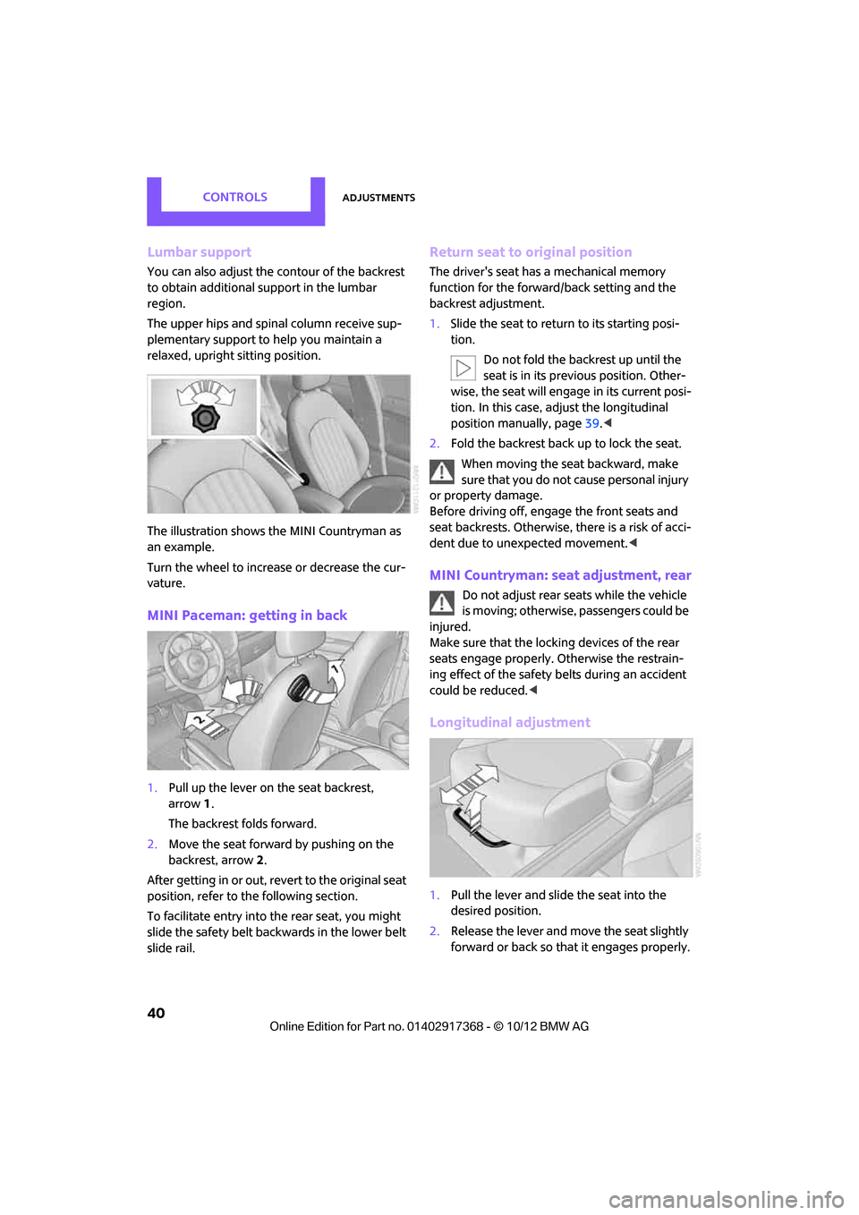
Lumbar support
You can also adjust the contour of the backrest
to obtain additional support in the lumbar
region.
The upper hips and spinal column receive sup-
plementary support to help you maintain a
relaxed, upright sitting position.
The illustration shows the MINI Countryman as
an example.
Turn the wheel to increase or decrease the cur-
vature.
MINI Paceman: getting in back
1. Pull up the lever on the seat backrest,
arrow 1.
The backrest folds forward.
2. Move the seat forward by pushing on the
backrest, arrow 2.
After getting in or out, revert to the original seat
position, refer to the following section.
To facilitate entry into the rear seat, you might
slide the safety belt backwards in the lower belt
slide rail.
Return seat to original position
The driver's seat has a mechanical memory
function for the forward/back setting and the
backrest adjustment.
1. Slide the seat to return to its starting posi-
tion.
Do not fold the backrest up until the
seat is in its previous position. Other-
wise, the seat will engage in its current posi-
tion. In this case, ad just the longitudinal
position manually, page 39.<
2. Fold the backrest back up to lock the seat.
When moving the seat backward, make
sure that you do not cause personal injury
or property damage.
Before driving off, enga ge the front seats and
seat backrests. Otherwise, there is a risk of acci-
dent due to unexpected movement. <
MINI Countryman: seat adjustment, rear
Do not adjust rear seats while the vehicle
is moving; otherwise, passengers could be
injured.
Make sure that the locking devices of the rear
seats engage properly. Otherwise the restrain-
ing effect of the safety belts during an accident
could be reduced. <
Longitudinal adjustment
1.Pull the lever and slide the seat into the
desired position.
2. Release the lever and mo ve the seat slightly
forward or back so that it engages properly.
00320051004F004C00510048000300280047004C0057004C005200510003
Page 42 of 275

AdjustmentsCONTROLS
41
Backrest
Adjusting backrest angle, refer to page106.
Head restraints
Correctly adjusted head restraint
A correctly adjusted head restraint reduces the
risk of neck injury in the event of an accident.
Correctly adjust the he ad restraints of all
occupied seats; otherwise, there is an
increased risk of injury in an accident. <
Height
Adjust the head restraint so that its center is
approximately at ear level.
Height adjustment
To raise: pull up.
To lower: press the button, arrow 1, and slide
the head restraint down.
Removing
Only remove a head restraint if no one will be
sitting on the seat in question. Reinstall the head restraint before trans-
porting passengers, as otherwise the head
restraint cannot provide its protective func-
tion. <
Front
1.Pull up as far as it will go.
2. Fold the backrest back slightly.
3. Press button 1 and pull the head restraint
out as far as it will go.
4. MINI Countryman: press the additional
button 2 with a suitable tool.
5. Pull out the head restraint.
6. Fold back the backrest.
Rear
1.Pull up as far as it will go.
2. Fold the backrest forward slightly.
3. Press button 1 and pull the head restraint
out as far as it will go.
4. Press the additional button 2 with a suitable
tool.
5. Pull the head restraint all the way out.
6. Fold rear seat backrest back into position.
00320051004F004C00510048000300280047004C0057004C005200510003
Page 47 of 275

CONTROLSTransporting children safely
46
Transporting children safely
Vehicle equipment
In this chapter, all production, country, and
optional equipment that is offered in the model
range is described. Equipment is also described
that is not available because of, for example,
selected options or coun try version. This also
applies to safety relate d functions and systems.
The right place for
children
Do not leave children unattended in the
vehicle; otherwise, they could endanger
themselves and/or other persons by opening the
doors, for example. <
Children should always sit in the rear
Accident research has shown that the safest
place for children is on the rear seat.
Only transport children under the age of
13 or smaller than 5 ft/150 cm in the rear
in a child restraint system suitable for their age,
weight and size. Otherwise, there is an
increased risk of injury in the event of an acci-
dent. <
Children 13 years of age or older must be buck-
led in with a safety belt as soon as there no
longer is any child restraint system that is appro-
priate for their age, size and weight.
Exception for front passenger seat
Front passenger airbags
Should it be necessary to use a child
restraint system on the front passenger
seat, the front and side airbags must be deacti-
vated. Otherwise, there is an increased risk of
injury to the child if th e airbags deploy, even if
the child is seated in a child restraint system.< For more information on
automatic deactivation
of the front passenger airbags, refer to page 82.
Child restraint systems,
installation
Before installing a child restraint system on the
rear seats, move the seat as far back as possible.
5-seater: adjust the inclination of the center
backrest to the respective outer backrest.
After the child restr aint system has been
installed on the respecti ve rear seat, move the
backrest forward so that the it rests lightly
against the child restrain t system, refer to Rear
seat backrests on page 107.
Observe the child restraint system manu-
facturer's instructions when selecting,
installing and using child restraint systems. Oth-
erwise, the protective effect may be dimin-
ished. <
On the front passenger seat
After installing a chil d restraint system on
the front passenger se at, make sure that
the front, side, and knee airbags for the front
passenger are deactivated; otherwise, there is
an increased risk of inju ry if the airbags deploy.<
Seat position
Before installing a child restraint system, move
the front passenger seat as far back and up as
possible to obtain the be st possible position for
the belt. Do not change the seat position after
this.
00320051004F004C00510048000300280047004C0057004C005200510003
Page 51 of 275
CONTROLSDriving
50
Driving
Vehicle equipment
In this chapter, all production, country, and
optional equipment that is offered in the model
range is described. Equipment is also described
that is not available because of, for example,
selected options or coun try version. This also
applies to safety relate d functions and systems.
Ignition lock
Inserting the key into the ignition lock
Insert the key all the way into the ignition lock.
Radio readiness
Individual electrical consumers can operate.
Removing the key from the ignition lock
Press in the key briefly. It is ejected slightly.
At the same time:
>The ignition is switched off if it was on
beforehand.
Automatic transmission
The key can only be removed if the selector lever
is in position P: interlock.
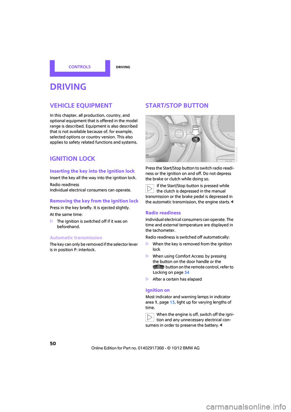
Start/Stop button
Press the Start/Stop button to switch radio readi-
ness or the ignition on and off. Do not depress
the brake or clutch while doing so.
If the Start/Stop button is pressed while
the clutch is depressed in the manual
transmission or the brake pedal is depressed in
the automatic transmission, the engine starts. <
Radio readiness
Individual electrical consumers can operate. The
time and external temperature are displayed in
the tachometer.
Radio readiness is switched off automatically:
>When the key is removed from the ignition
lock
> When using Comfort Access
by pressing
the button on the door handle or the
button on the remote control, refer to
Locking on page 34
> After a certain has elapsed
Ignition on
Most indicator and warn ing lamps in indicator
area 1, page 13, light up for varying lengths of
time.
When the engine is off, switch off the igni-
tion and any unnecessary electrical con-
sumers in order to preserve the battery. <
00320051004F004C00510048000300280047004C0057004C005200510003
Page 53 of 275
CONTROLSDriving
52
Automatic transmission
1.With the car at a stop, move the selector
lever to position P.
2. Press the Start/Stop button.
3. Forcefully apply the parking brake.
Before driving into a car wash
By following these steps, the vehicle is able to
roll:
1.Place the remote control, even with Comfort
Access, in the ignition lock.
2. Depress the brake.
3. Move the selector lever to position N.
4. Switch off the engine.
Parking brake
The parking brake is primarily intended to pre-
vent the vehicle from rolling while parked; it
brakes the rear wheels.
In addition, follow the instructions on page 51
under Switching off the engine.
Applying
The lever locks in position automatically.
Releasing
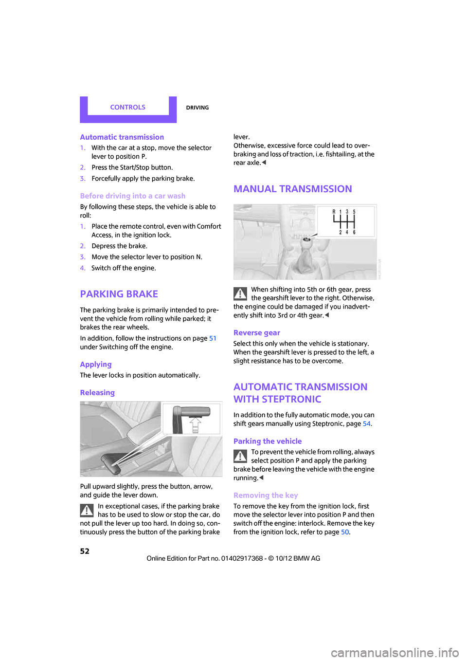
Pull upward slightly, pr ess the button, arrow,
and guide the lever down.
In exceptional cases, if the parking brake
has to be used to slow or stop the car, do
not pull the lever up too hard. In doing so, con-
tinuously press the button of the parking brake lever.
Otherwise, excessive force could lead to over-
braking and loss of traction
, i.e. fishtailing, at the
rear axle. <
Manual transmission
When shifting into 5t h or 6th gear, press
the gearshift lever to the right. Otherwise,
the engine could be damaged if you inadvert-
ently shift into 3rd or 4th gear. <
Reverse gear
Select this only when the vehicle is stationary.
When the gearshift lever is pressed to the left, a
slight resistance has to be overcome.
Automatic transmission
with Steptronic
In addition to the fully automatic mode, you can
shift gears manually using Steptronic, page 54.
Parking the vehicle
To prevent the vehicle from rolling, always
select position P and apply the parking
brake before leaving the vehicle with the engine
running. <
Removing the key
To remove the key from the ignition lock, first
move the selector lever into position P and then
switch off the engine: in terlock. Remove the key
from the ignition lock, refer to page 50.
00320051004F004C00510048000300280047004C0057004C005200510003
Page 56 of 275
DrivingCONTROLS
55
The extractor hook is in the onboard
document holder or in the pouch for
the tire-changing set, page 232.<
4. Pull the loop up.
5. Move the selector le ver into the desired
position by pressing the button on the front
of the selector lever.
Before manually unlocking the selector
lever lock, firmly set the parking brake to
prevent the vehicle from rolling away. <
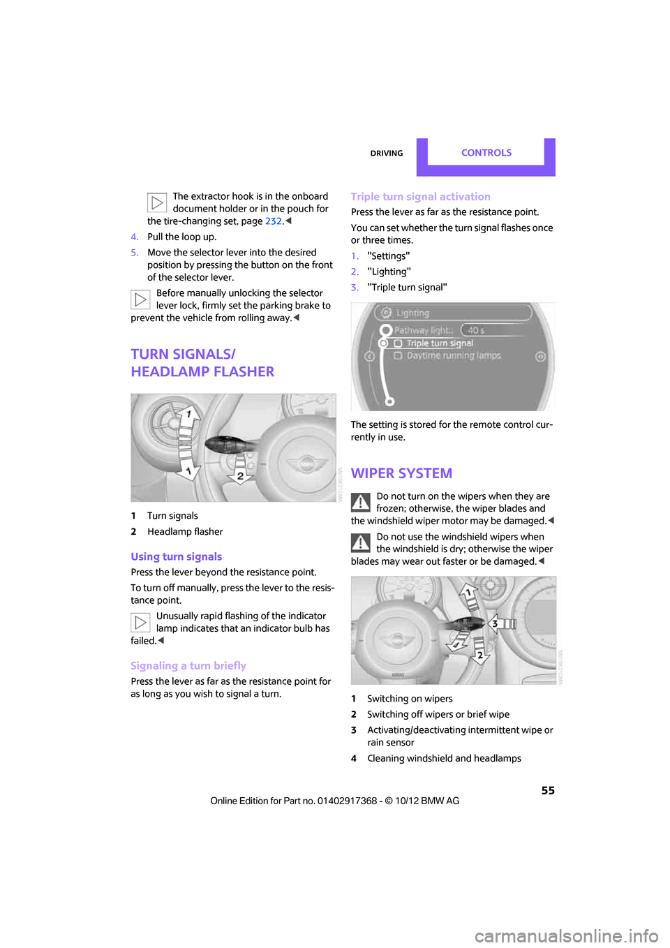
Turn signals/
headlamp flasher
1Turn signals
2 Headlamp flasher
Using turn signals
Press the lever beyond the resistance point.
To turn off manually, pre ss the lever to the resis-
tance point.
Unusually rapid flashi ng of the indicator
lamp indicates that an indicator bulb has
failed. <
Signaling a turn briefly
Press the lever as far as the resistance point for
as long as you wish to signal a turn.
Triple turn signal activation
Press the lever as far as the resistance point.
You can set whether the turn signal flashes once
or three times.
1. "Settings"
2. "Lighting"
3. "Triple turn signal"
The setting is stored for the remote control cur-
rently in use.
Wiper system
Do not turn on the wipers when they are
frozen; otherwise, the wiper blades and
the windshield wiper motor may be damaged. <
Do not use the windshield wipers when
the windshield is dry; otherwise the wiper
blades may wear out faster or be damaged. <
1 Switching on wipers
2 Switching off wipers or brief wipe
3 Activating/deactivating intermittent wipe or
rain sensor
4 Cleaning windshield and headlamps
00320051004F004C00510048000300280047004C0057004C005200510003
Page 58 of 275
DrivingCONTROLS
57
Deactivating intermittent wipe or rain
sensor
Press the button again, arrow3.
Brief wipe
Press the lever downward once, arrow 2.
Cleaning windshield and headlamps
Pull the lever, arrow 4.
Washer fluid is sprayed onto the windshield and
the wipers are operated briefly.
When the vehicle lighting system is switched on,
the headlamps are cleaned at regular and
appropriate intervals.
In cars equipped with an alarm system, the
headlamps cannot be cleaned when the hood is
open. Do not use the washers when the washer
fluid reservoir is empt y; otherwise, you will
damage the washer pump.
Only use the washers if the hood has been com-
pletely closed; otherwise, the headlamp washer
system
may be damaged. Do not use the wash-
ers if there is any danger that the fluid will freeze
on the windshield. If you do, your vision could be
obscured. For this reason, use antifreeze. <
Window washer nozzles
The window washer nozzles are heated auto-
matically while the engine is running or the igni-
tion is switched on.
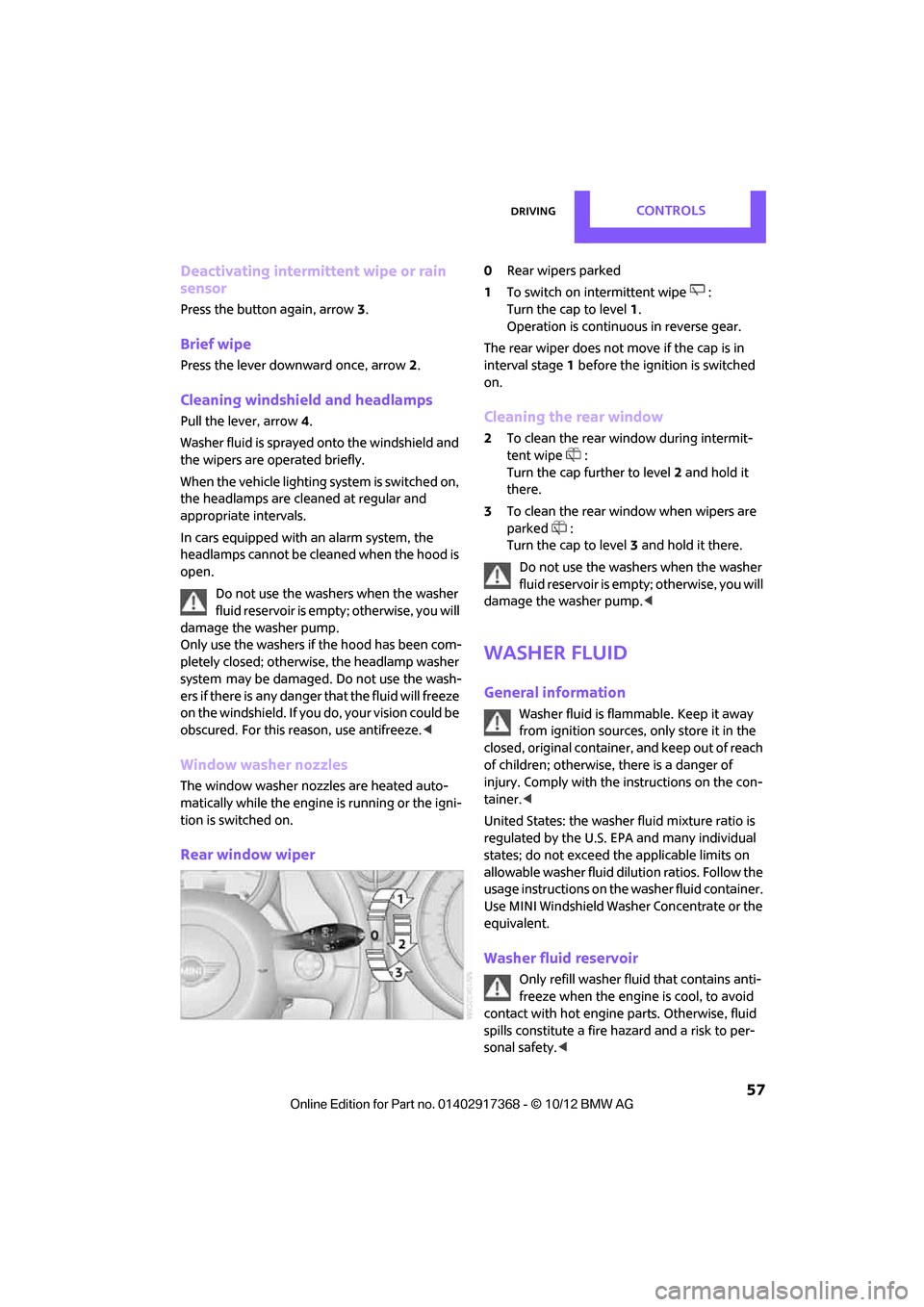
Rear window wiper
0Rear wipers parked
1 To switch on intermittent wipe :
Turn the cap to level 1.
Operation is continuous in reverse gear.
The rear wiper does not move if the cap is in
interval stage 1 before the ignition is switched
on.
Cleaning the rear window
2 To clean the rear window during intermit-
tent wipe :
Turn the cap further to level 2 and hold it
there.
3 To clean the rear window when wipers are
parked :
Turn the cap to level 3 and hold it there.
Do not use the washers when the washer
fluid reservoir is empty; otherwise, you will
damage the washer pump. <
Washer fluid
General information
Washer fluid is flammable. Keep it away
from ignition sources, only store it in the
closed, original container, and keep out of reach
of children; otherwise, there is a danger of
injury. Comply with the instructions on the con-
tainer. <
United States: the washer fluid mixture ratio is
regulated by the U.S. EPA and many individual
states; do not exceed the applicable limits on
allowable washer fluid dilution ratios. Follow the
usage instructions on the washer fluid container.
Use MINI Windshield Washer Concentrate or the
equivalent.
Washer fluid reservoir
Only refill washer fl uid that contains anti-
freeze when the engine is cool, to avoid
contact with hot engine parts. Otherwise, fluid
spills constitute a fire hazard and a risk to per-
sonal safety. <
00320051004F004C00510048000300280047004C0057004C005200510003
Page 60 of 275
DrivingCONTROLS
59
Increasing speed
Press button1 repeatedly until the desired
speed is reached. Every time you press the but-
ton, the speed increases by approx. 1 mph or
1km/h.
Accelerating using the button
Press and hold button 1.
The vehicle accelerates wi thout pressure on the
accelerator pedal. After the button is released,
the driving speed is maintained and stored.
Decreasing speed
Press button 3 repeatedly until the desired
speed is reached.
The functions here are the same as for increas-
ing the speed or accelerating, except that the
speed will be decreased.
Resuming a speed stored beforehand
Press button 4.
The last speed stored is achieved again and
maintained.
The stored speed is cleared when the ignition is
switched off.
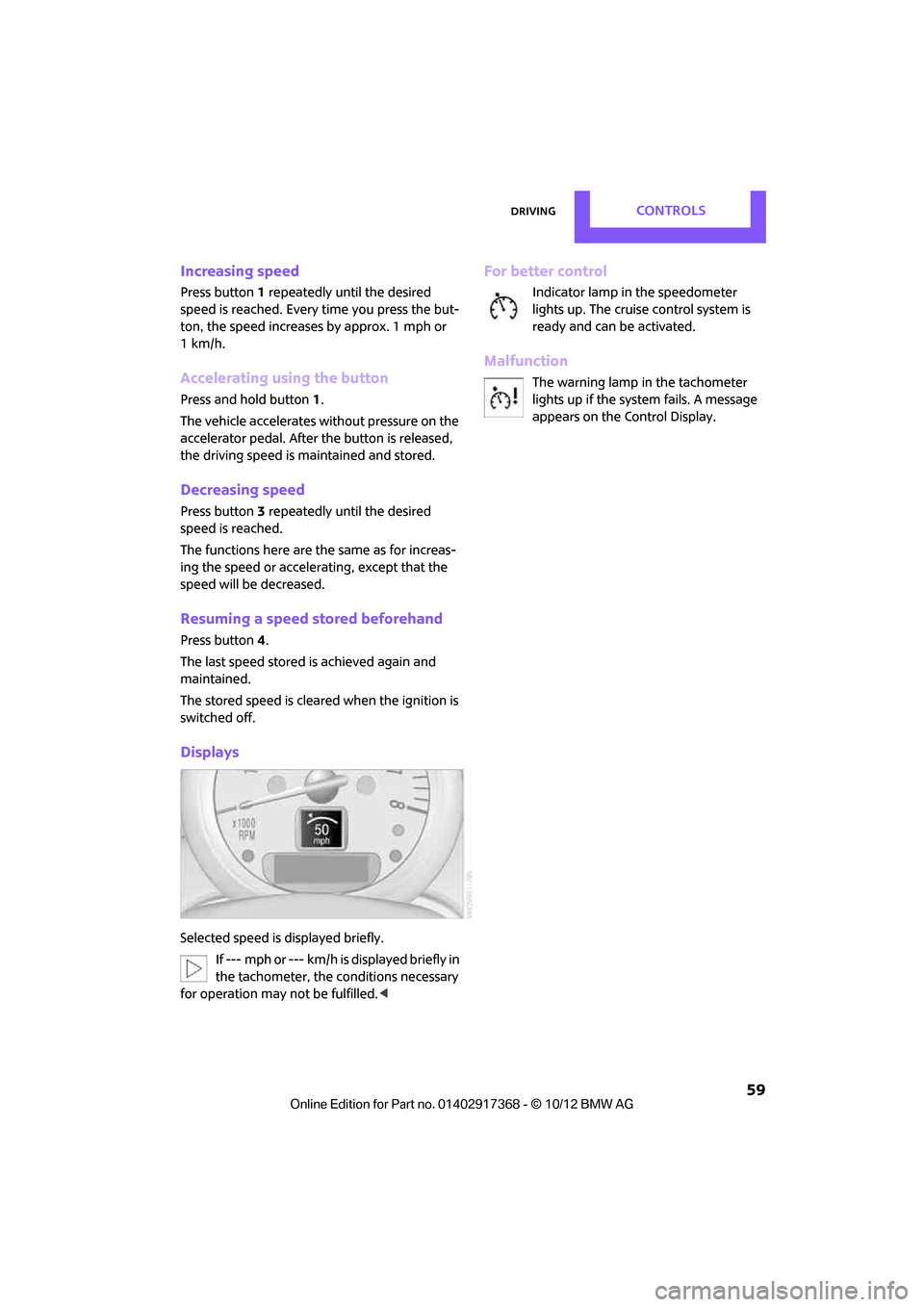
Displays
Selected speed is displayed briefly. If --- mph or --- km/h is displayed briefly in
the tachometer, the conditions necessary
for operation may not be fulfilled.<
For better control
Indicator lamp in the speedometer
lights up. The cruise control system is
ready and can be activated.
Malfunction
The warning lamp in the tachometer
lights up if the system fails. A message
appears on the Control Display.
00320051004F004C00510048000300280047004C0057004C005200510003
Page 61 of 275
CONTROLSControls overview
60
Controls overview
Vehicle equipment
In this chapter, all production, country, and
optional equipment that is offered in the model
range is described. Equipment is also described
that is not available because of, for example,
selected options or coun try version. This also
applies to safety relate d functions and systems.
Fuel gauge
Fuel tank capacity
Approx. 12.4 US gal/47 liters.
You will find information on refueling on
page 201.
If the tilt of the vehicle varies for a longer period,
when you are driving in mountainous areas, for
example, the indicator may fluctuate slightly.
The arrow next to the gas pump symbol of the
fuel gauge points toward the side of the vehicle
with the fuel filler flap.
Reserve
Once the fuel level has fallen to the reserve zone
of approx. 2.1 US gal/8 liters the remaining LEDs
change from orange to red, arrow, and a mes-
sage is displayed briefly on the Control Display.
The tachometer
displays the remaining cruising
range. When the range is less than approx.
30 miles/50 km, the messa ge remains in the
Control Display. If the range displayed is less than
30 miles/50 km, be sure to refuel; other-
wise, engine functions are not guaranteed and
damage may occur. <
With a dynamic driving style, e.g. rapid corner-
ing, engine functions are not always assured.
Tachometer
Never operate the engine with the needle in the
red overspeed zone of the gauge. In this range,
the fuel supply is interrupted to protect the
engine.
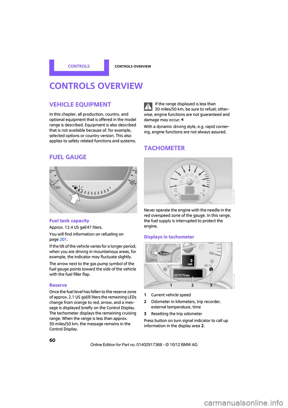
Displays in tachometer
1Current vehicle speed
2 Odometer in kilometers, trip recorder,
external temperature, time
3 Resetting the trip odometer
Press button on turn signal indicator to call up
information in the display area 2.
00320051004F004C00510048000300280047004C0057004C005200510003