ESP MINI Paceman 2016 Owner's Manual (Mini Connected)
[x] Cancel search | Manufacturer: MINI, Model Year: 2016, Model line: Paceman, Model: MINI Paceman 2016Pages: 223, PDF Size: 5.52 MB
Page 7 of 223
be necessary to adapt your vehicle to poten‐
tially differing operating conditions and permit
requirements. If your vehicle does not comply
with the homologation requirements in a cer‐
tain country you may not be able to lodge war‐
ranty claims for your vehicle there. Further in‐
formation on warranty is available from a
dealer’s service center.
Maintenance and repairs
Advanced technology, e.g., the use of modern
materials and high-performance electronics,
requires suitable maintenance and repair work.
The manufacturer of your vehicle recommends
that you entrust corresponding procedures to a
MINI dealer’s service center. If you choose to
use another service facility, the manufacturer of
your vehicle recommends use of a facility that
performs work, e.g. maintenance and repair,
according to MINI specifications with properly
trained personnel, referred to in this Owner's
Manual as "another qualified service center or
repair shop".
If work is performed improperly, e.g. mainte‐
nance and repair, there is a risk of subsequent
damage and related safety risks.
Parts and accessories The manufacturer of your vehicle recommends
the use of parts and accessory products ap‐ proved by the manufacturer of the MINI.
Approved parts and accessories, and advice on
their use and installation are available from a
MINI dealer's service center.
MINI parts and accessories were tested by the
manufacturer of the MINI for their safety and
suitability in MINI vehicles.
The manufacturer of your vehicle warrants gen‐
uine MINI parts and accessories.
The manufacturer of your vehicle does not
evaluate whether each individual product from
another manufacturer can be used with MINI
vehicles without presenting a safety hazard,
even if a country-specific official approval wasissued. The manufacturer of your vehicle does
not evaluate whether these products are suita‐
ble for MINI vehicles under all usage conditions.
California Proposition 65 Warning
California laws require us to state the following
warning:
Engine exhaust and a wide variety of automo‐
bile components and parts, including compo‐
nents found in the interior furnishings in a vehi‐
cle, contain or emit chemicals known to the
State of California to cause cancer and birth de‐
fects and reproductive harm. In addition, cer‐
tain fluids contained in vehicles and certain
products of component wear contain or emit
chemicals known to the State of California to
cause cancer and birth defects or other repro‐
ductive harm. Battery posts, terminals and re‐
lated accessories contain lead and lead com‐
pounds. Wash your hands after handling. Used
engine oil contains chemicals that have caused
cancer in laboratory animals. Always protect
your skin by washing thoroughly with soap and
water.
Service and warranty
We recommend that you read this publication
thoroughly. Your vehicle is covered by the fol‐
lowing warranties:▷New Vehicle Limited Warranty.▷Rust Perforation Limited Warranty.▷Federal Emissions System Defect Warranty.▷Federal Emissions Performance Warranty.▷California Emission Control System Limited
Warranty.
Detailed information about these warranties is
listed in the Service and Warranty Information
Booklet for US models or in the Warranty and
Service Guide Booklet for Canadian models.
Your vehicle has been specifically adapted and
designed to meet the particular operating con‐
ditions and homologation requirements in your
country and continental region in order to de‐
Seite 7Information7
Online Edition for Part no. 01 40 2 964 433 - VI/15
Page 8 of 223
liver the full driving pleasure while the vehicle is
operated under those conditions. If you wish to
operate your vehicle in another country or re‐
gion, you may be required to adapt your vehi‐
cle to meet different prevailing operating con‐
ditions and homologation requirements. You
should also be aware of any applicable war‐
ranty limitations or exclusions for such country
or region. In such case, please contact Cus‐
tomer Relations for further information.
Maintenance
Maintain the vehicle regularly to sustain the
road safety, operational reliability and the New
Vehicle Limited Warranty.
Specifications for required maintenance meas‐
ures:▷MINI Maintenance system▷Service and Warranty Information Booklet
for US models▷Warranty and Service Guide Booklet for
Canadian models
If the vehicle is not maintained according to
these specifications, this could result in serious
damage to the vehicle. Such damage is not
covered by the MINI New Vehicle Limited War‐
ranty.
Data memory
Many electronic components on your vehicle
are equipped with data memories that tempo‐
rarily or permanently store technical informa‐
tion about the condition of the vehicle, events
and faults. This technical information generally
records the state of a component, a module, a
system or the environment:
▷Operating mode of system components, fill
levels for instance.▷Status messages for the vehicle and from its
individual components, e.g., wheel rotation
speed/vehicle speed, deceleration, trans‐
verse acceleration.▷Malfunctions and malfunctions in important
system components, e.g., lights and brakes.▷Responses by the vehicle to special situa‐
tions such as airbag deployment or engag‐
ing the stability control system.▷Ambient conditions, such as temperature.
This data is purely technical in nature and is
used to detect and correct faults and to opti‐
mize vehicle functions. Motion profiles over
routes traveled cannot be created from this
data. When service offerings are used, e.g., re‐
pair services, service processes, warranty
claims, quality assurance, this technical infor‐
mation can be read out from the event and
fault memories by employees of the dealer’s
service center or another qualified service cen‐
ter or repair shop, including the manufacturer,
using special diagnostic tools. You can obtain
further information there if you need it. After
an error is corrected, the information in the
fault memory is deleted or overwritten on a
continuous basis.
With the vehicle in use there are situations
where you can associate these technical data
with individuals if combined with other infor‐
mation, e.g., an accident report, damage to the
vehicle, eye witness accounts — possibly with
the assistance of an expert.
Additional functions that are contractually
agreed with the customer - such as vehicle
emergency locating - you can transmit certain
vehicle data from the vehicle.
Event Data Recorder EDR
This vehicle is equipped with an event data re‐
corder EDR. The main purpose of an EDR is to
record, in certain crash or near crash-like situa‐
tions, such as an air bag deployment or hitting
a road obstacle, data that will assist in under‐
standing how a vehicle's systems performed.
The EDR is designed to record data related to
vehicle dynamics and safety systems for a short
period of time, typically 30 seconds or less.
Seite 8Information8
Online Edition for Part no. 01 40 2 964 433 - VI/15
Page 15 of 223
Indicator/warning lights
The principle
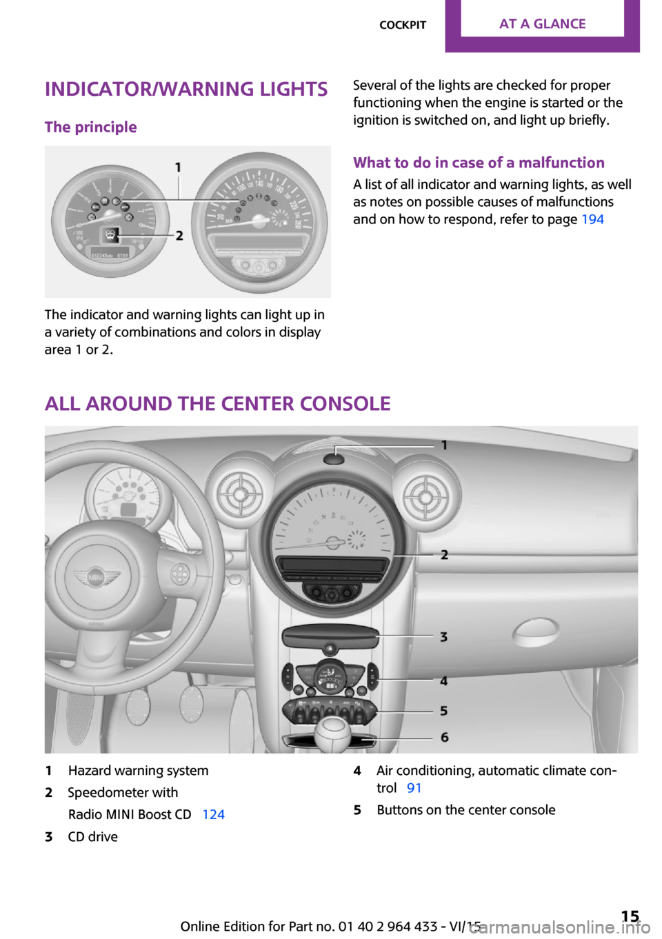
The indicator and warning lights can light up in
a variety of combinations and colors in display
area 1 or 2.
Several of the lights are checked for proper
functioning when the engine is started or the
ignition is switched on, and light up briefly.
What to do in case of a malfunction
A list of all indicator and warning lights, as well
as notes on possible causes of malfunctions
and on how to respond, refer to page 194
All around the center console
1Hazard warning system2Speedometer with
Radio MINI Boost CD 1243CD drive4Air conditioning, automatic climate con‐
trol 915Buttons on the center consoleSeite 15CockpitAT A GLANCE15
Online Edition for Part no. 01 40 2 964 433 - VI/15
Page 21 of 223
Personal Profile
The concept
You can set several of your vehicle's functions
to suit your personal needs and preferences.▷Through Personal Profile, most of these set‐
tings are stored for the remote control cur‐
rently in use.▷While the vehicle is being unlocked, the re‐
mote control is recognized and the settings
stored with it are called up and imple‐
mented.▷Your personal settings will be recognized
and called up again even if the vehicle has
been used in the meantime by someone
else with another remote control.▷The individual settings are stored for no
more than three remote controls.
Personal Profile settings
The following functions and settings can be
stored in a profile.
More information on the settings can be found
under:
▷Response of the central locking system
when the car is being unlocked, refer to
page 22.▷Automatic locking of the vehicle, refer to
page 26.▷Triple turn signal activation, refer to
page 53.▷Settings for the displays in the speedometer
and tachometer:▷12h/24h clock format, refer to
page 64.▷Date format, refer to page 64.▷Units of measure for fuel consumption,
distance covered/remaining distances,
and temperature, refer to page 64.▷Light settings:▷Headlight courtesy delay feature, refer
to page 71.▷Daytime running lights, refer to
page 70.▷Automatic climate control, refer to
page 93: AUTO program, activating/deac‐
tivating the cooling function, setting the
temperature, air volume, and air distribu‐
tion.▷Entertainment:▷Last entertainment source.▷Radio MINI Boost CD:
Tone settings, refer to page 126.
Volume, refer to page 126.
Central locking system
The concept
The central locking system becomes active
when the driver's door is closed.
The system simultaneously engages and re‐
leases the locks on the following:
▷Doors.▷Tailgate.▷Fuel filler flap.
Operating from the outside
▷Via the remote control.▷Via the door lock.▷In cars with Comfort Access, via the door
handles on the driver's and front passenger
sides.
The following takes place simultaneously when
locking/unlocking the vehicle via the remote
control:
▷Depending on the vehicle equipment, the
anti-theft protection is switched on and off
as well. The anti-theft protection makes it
impossible to unlock the doors using the
lock buttons or door handles.Seite 21Opening and closingCONTROLS21
Online Edition for Part no. 01 40 2 964 433 - VI/15
Page 29 of 223
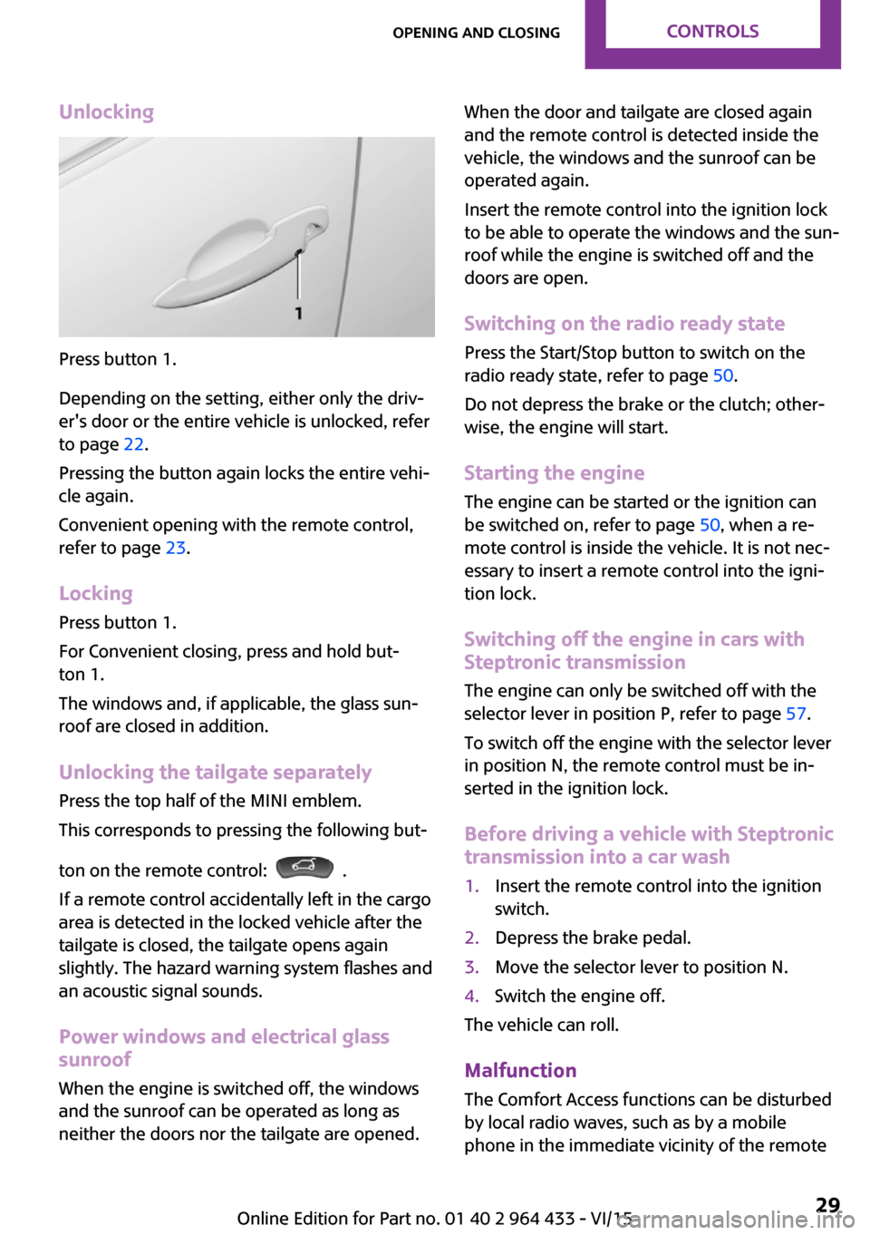
Unlocking
Press button 1.
Depending on the setting, either only the driv‐
er's door or the entire vehicle is unlocked, refer
to page 22.
Pressing the button again locks the entire vehi‐
cle again.
Convenient opening with the remote control,
refer to page 23.
Locking
Press button 1.
For Convenient closing, press and hold but‐
ton 1.
The windows and, if applicable, the glass sun‐
roof are closed in addition.
Unlocking the tailgate separately
Press the top half of the MINI emblem.
This corresponds to pressing the following but‐
ton on the remote control:
.
If a remote control accidentally left in the cargo
area is detected in the locked vehicle after the
tailgate is closed, the tailgate opens again
slightly. The hazard warning system flashes and
an acoustic signal sounds.
Power windows and electrical glass
sunroof
When the engine is switched off, the windows
and the sunroof can be operated as long as
neither the doors nor the tailgate are opened.
When the door and tailgate are closed again
and the remote control is detected inside the
vehicle, the windows and the sunroof can be
operated again.
Insert the remote control into the ignition lock
to be able to operate the windows and the sun‐
roof while the engine is switched off and the
doors are open.
Switching on the radio ready state Press the Start/Stop button to switch on the
radio ready state, refer to page 50.
Do not depress the brake or the clutch; other‐
wise, the engine will start.
Starting the engine The engine can be started or the ignition can
be switched on, refer to page 50, when a re‐
mote control is inside the vehicle. It is not nec‐
essary to insert a remote control into the igni‐
tion lock.
Switching off the engine in cars with
Steptronic transmission
The engine can only be switched off with the
selector lever in position P, refer to page 57.
To switch off the engine with the selector lever
in position N, the remote control must be in‐
serted in the ignition lock.
Before driving a vehicle with Steptronic
transmission into a car wash1.Insert the remote control into the ignition
switch.2.Depress the brake pedal.3.Move the selector lever to position N.4.Switch the engine off.
The vehicle can roll.
Malfunction The Comfort Access functions can be disturbed
by local radio waves, such as by a mobile
phone in the immediate vicinity of the remote
Seite 29Opening and closingCONTROLS29
Online Edition for Part no. 01 40 2 964 433 - VI/15
Page 31 of 223
Arming and disarming the alarm system
General information
When the vehicle is locked and unlocked, the
alarm system is armed and disarmed at the
same time.
Door lock and armed alarm systemUnlocking via the door lock will trigger the
alarm on some market-specific versions.
To stop this alarm, unlock the vehicle with the
remote control or switch on the ignition.
Tailgate with armed alarm system The tailgate, refer to page 24, can also be
opened when the alarm system is armed.
Press the button on the remote con‐
trol.
When you subsequently close the tailgate, it is
again locked and monitored.
Unlocking via the door lock will trigger the
alarm on some market-specific versions.
Switching off the alarm
▷Unlock the vehicle using the remote con‐
trol, refer to page 22.▷Insert the remote control all the way into
the ignition lock.▷With Comfort Access and if you are carrying
the remote control with you, push the but‐
ton on the door lock.
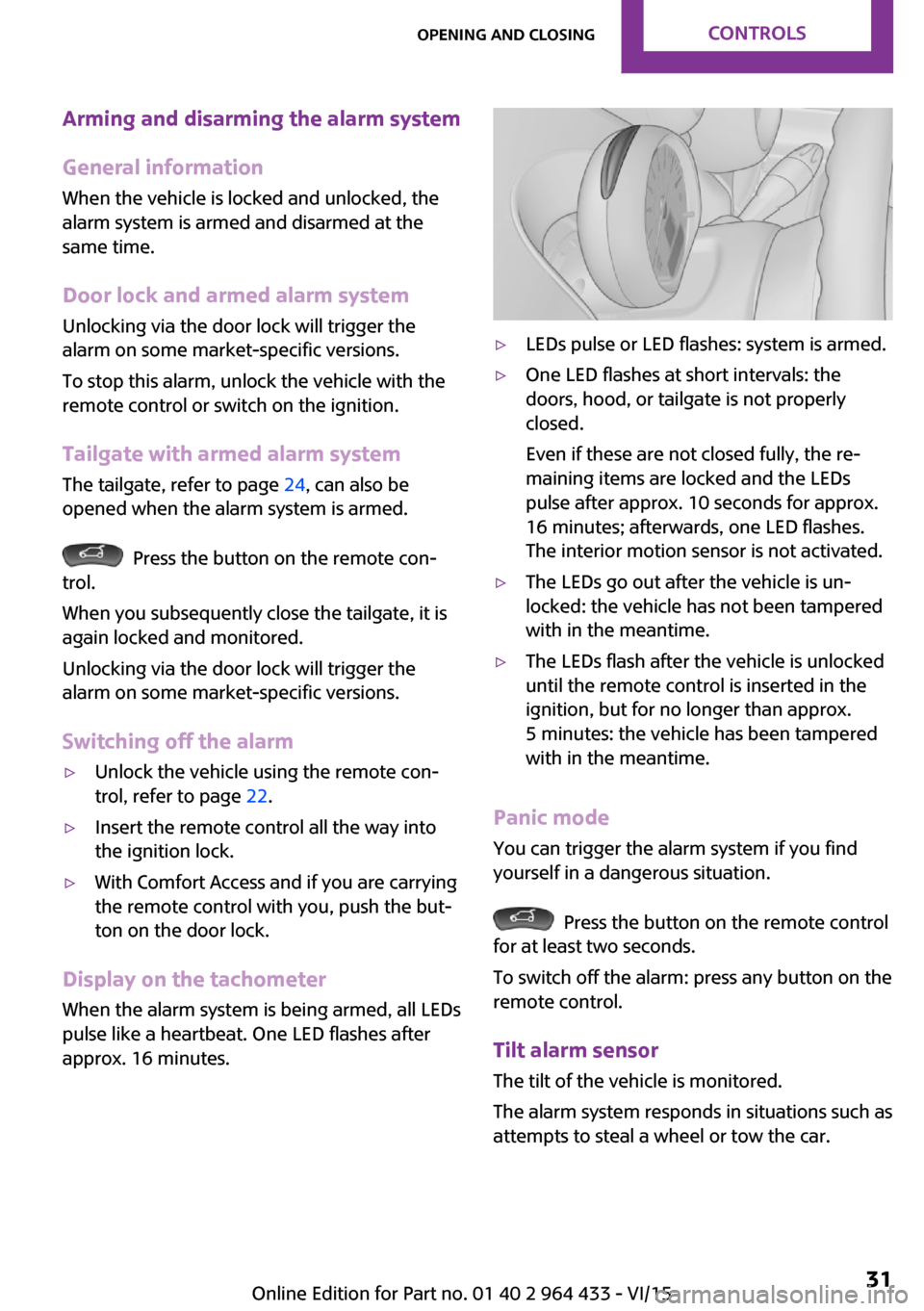
Display on the tachometer
When the alarm system is being armed, all LEDs
pulse like a heartbeat. One LED flashes after
approx. 16 minutes.
▷LEDs pulse or LED flashes: system is armed.▷One LED flashes at short intervals: the
doors, hood, or tailgate is not properly
closed.
Even if these are not closed fully, the re‐
maining items are locked and the LEDs
pulse after approx. 10 seconds for approx.
16 minutes; afterwards, one LED flashes.
The interior motion sensor is not activated.▷The LEDs go out after the vehicle is un‐
locked: the vehicle has not been tampered
with in the meantime.▷The LEDs flash after the vehicle is unlocked
until the remote control is inserted in the
ignition, but for no longer than approx.
5 minutes: the vehicle has been tampered
with in the meantime.
Panic mode
You can trigger the alarm system if you find
yourself in a dangerous situation.
Press the button on the remote control
for at least two seconds.
To switch off the alarm: press any button on the
remote control.
Tilt alarm sensor
The tilt of the vehicle is monitored.
The alarm system responds in situations such as
attempts to steal a wheel or tow the car.
Seite 31Opening and closingCONTROLS31
Online Edition for Part no. 01 40 2 964 433 - VI/15
Page 39 of 223
The shoulder strap's anchorage point will be
correct for adult seat occupants of every build if
the seat is correctly adjusted.
WARNING
If the safety belt is used by more than
one person, the protective effect of the safety
belt cannot be ensured anymore. There is risk
of injuries or danger to life. Do not allow more
than one person to wear a single safety belt. In‐
fants and children are not allowed in an occu‐
pant's lap, but must be transported and respec‐
tively secured in designated child restraint
systems. ◀
WARNING
The protective effect of the safety belts
can be limited or lost when safety belts are fas‐
tened incorrectly. An incorrectly fastened safety
belt can cause additional injuries, e.g. in the
event of an accident or during braking and eva‐
sive maneuvers. There is risk of injuries or dan‐
ger to life. Make sure that all occupants are
wearing safety belts correctly. ◀
WARNING
With a rear backrest that is not locked,
the protective function of the middle safety belt
is not guaranteed. There is risk of injuries or
danger to life. If you are using the middle safety
belt, lock the wider rear backrest. ◀
Correct use of safety belts▷Wear the belt twist-free and as tight to your
body as possible over your lap and should‐
ers.▷Wear the belt deep on your hips over your
lap. The belt may not press on your stom‐
ach.▷Do not wear the belt on your throat, rub it
on sharp edges, guide it or jam it in across
hard or fragile objects.▷Avoid thick clothing.▷Re-tighten the belt frequently upward
around your upper body.Buckling the belt
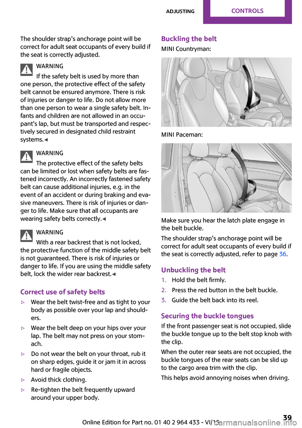
MINI Countryman:
MINI Paceman:
Make sure you hear the latch plate engage in
the belt buckle.
The shoulder strap's anchorage point will be
correct for adult seat occupants of every build if
the seat is correctly adjusted, refer to page 36.
Unbuckling the belt
1.Hold the belt firmly.2.Press the red button in the belt buckle.3.Guide the belt back into its reel.
Securing the buckle tongues
If the front passenger seat is not occupied, slide
the buckle tongue up to the belt stop knob with
the clip.
When the outer rear seats are not occupied, the
buckle tongues of the rear seats can be slid up
to the cargo area trim with the clip.
This helps avoid annoying noises when driving.
Seite 39AdjustingCONTROLS39
Online Edition for Part no. 01 40 2 964 433 - VI/15
Page 40 of 223
MINI Countryman: center safety belt of
rear seat
The belt buckle embossed with the word CEN‐
TER is intended exclusively for use by passen‐
gers riding in the center position.
If the center safety belt in the rear is used, the
backrests must be locked, refer to page 103.
The safety belt will not have a restraining effect
if the backrest is not locked.
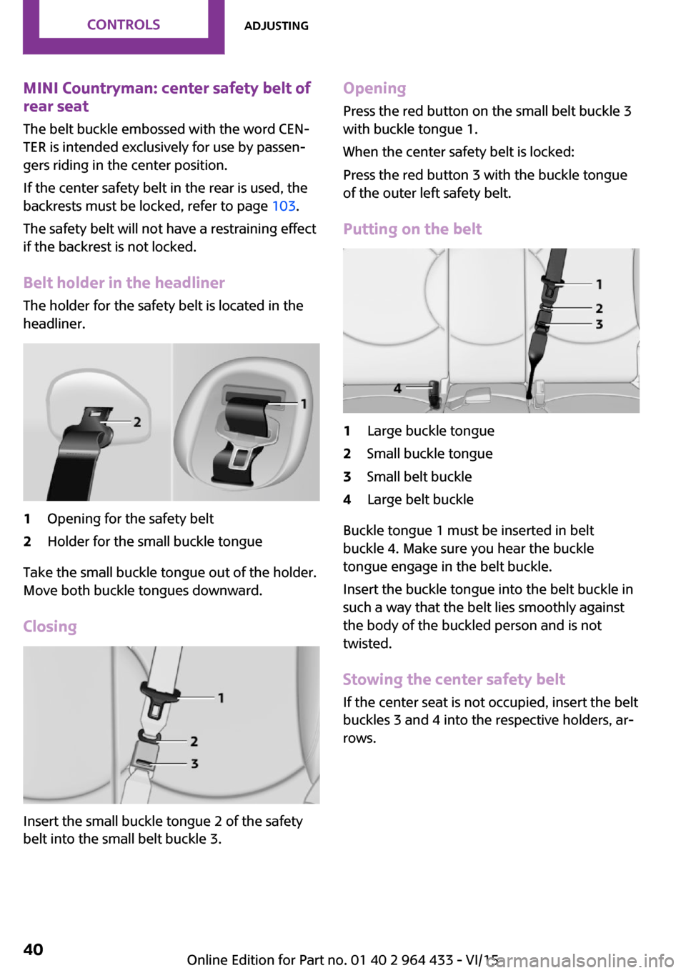
Belt holder in the headliner
The holder for the safety belt is located in the
headliner.1Opening for the safety belt2Holder for the small buckle tongue
Take the small buckle tongue out of the holder.
Move both buckle tongues downward.
Closing
Insert the small buckle tongue 2 of the safety
belt into the small belt buckle 3.
Opening
Press the red button on the small belt buckle 3
with buckle tongue 1.
When the center safety belt is locked:
Press the red button 3 with the buckle tongue
of the outer left safety belt.
Putting on the belt1Large buckle tongue2Small buckle tongue3Small belt buckle4Large belt buckle
Buckle tongue 1 must be inserted in belt
buckle 4. Make sure you hear the buckle
tongue engage in the belt buckle.
Insert the buckle tongue into the belt buckle in
such a way that the belt lies smoothly against
the body of the buckled person and is not
twisted.
Stowing the center safety belt
If the center seat is not occupied, insert the belt
buckles 3 and 4 into the respective holders, ar‐
rows.
Seite 40CONTROLSAdjusting40
Online Edition for Part no. 01 40 2 964 433 - VI/15
Page 43 of 223
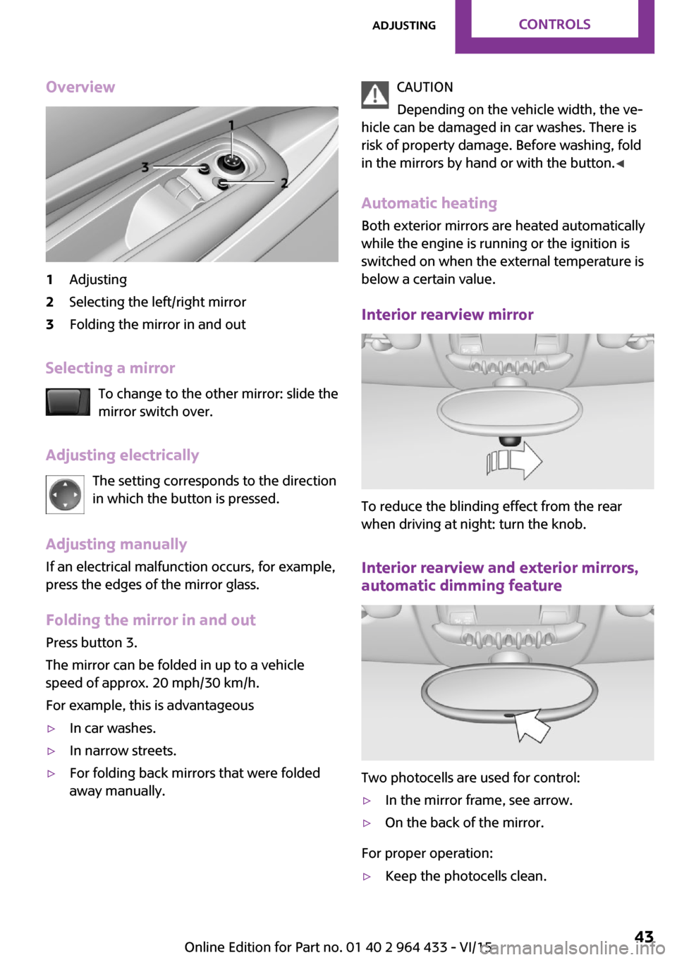
Overview1Adjusting2Selecting the left/right mirror3Folding the mirror in and out
Selecting a mirrorTo change to the other mirror: slide the
mirror switch over.
Adjusting electrically The setting corresponds to the direction
in which the button is pressed.
Adjusting manually If an electrical malfunction occurs, for example,
press the edges of the mirror glass.
Folding the mirror in and out
Press button 3.
The mirror can be folded in up to a vehicle
speed of approx. 20 mph/30 km/h.
For example, this is advantageous
▷In car washes.▷In narrow streets.▷For folding back mirrors that were folded
away manually.CAUTION
Depending on the vehicle width, the ve‐
hicle can be damaged in car washes. There is
risk of property damage. Before washing, fold
in the mirrors by hand or with the button. ◀
Automatic heating Both exterior mirrors are heated automatically
while the engine is running or the ignition is
switched on when the external temperature is
below a certain value.
Interior rearview mirror
To reduce the blinding effect from the rear
when driving at night: turn the knob.
Interior rearview and exterior mirrors,
automatic dimming feature
Two photocells are used for control:
▷In the mirror frame, see arrow.▷On the back of the mirror.
For proper operation:
▷Keep the photocells clean.Seite 43AdjustingCONTROLS43
Online Edition for Part no. 01 40 2 964 433 - VI/15
Page 46 of 223
securely against the backrest. If possible, adjust
the backrest tilt for all affected backrests and
correctly adjust the seats. Make sure that seats
and backrests are securely engaged. If possible,
adjust the height of the head restraints or re‐
move them. ◀
Installing child re‐ straint fixing systems
Before mounting MINI Countryman: before mounting a child re‐
straint fixing system on the rear seats, move
the seats into the rearmost positions.
Adjust the inclination of the center backrest to
that of the respective outer backrest.
After mounting the child restraint fixing system
on the respective outer rear seat, adjust the
backrest forward, if necessary, to ensure that
the backrest is in contact with the child re‐
straint fixing system. Rear seat backrests, refer
to page 102.
Information Pay attention to the specifications of the child
restraint system manufacturer when selecting,
installing, and using child restraint systems.
WARNING
The stability of the child restraint system
is limited or compromised with incorrect seat
adjustment or improper installation of the child seat. There is risk of injuries or danger to life.
Make sure that the child restraint system fits
securely against the backrest. If possible, adjust
the backrest tilt for all affected backrests and
correctly adjust the seats. Make sure that seats
and backrests are securely engaged. If possible,
adjust the height of the head restraints or re‐
move them. ◀On the front passenger seat
Deactivating the airbags After installing a child restraint fixing system on
the front passenger seat, ensure that the front,
side, and knee airbags on the front passenger
side are deactivated.
Seat position and height Before installing a child restraint fixing system,move the front passenger seat as far back aspossible and adjust its height to the highest po‐
sition to obtain the best possible position for
the belt and to offer optimal protection in the
event of an accident.
Do not change this seat position once it has
been set.
Child seat security
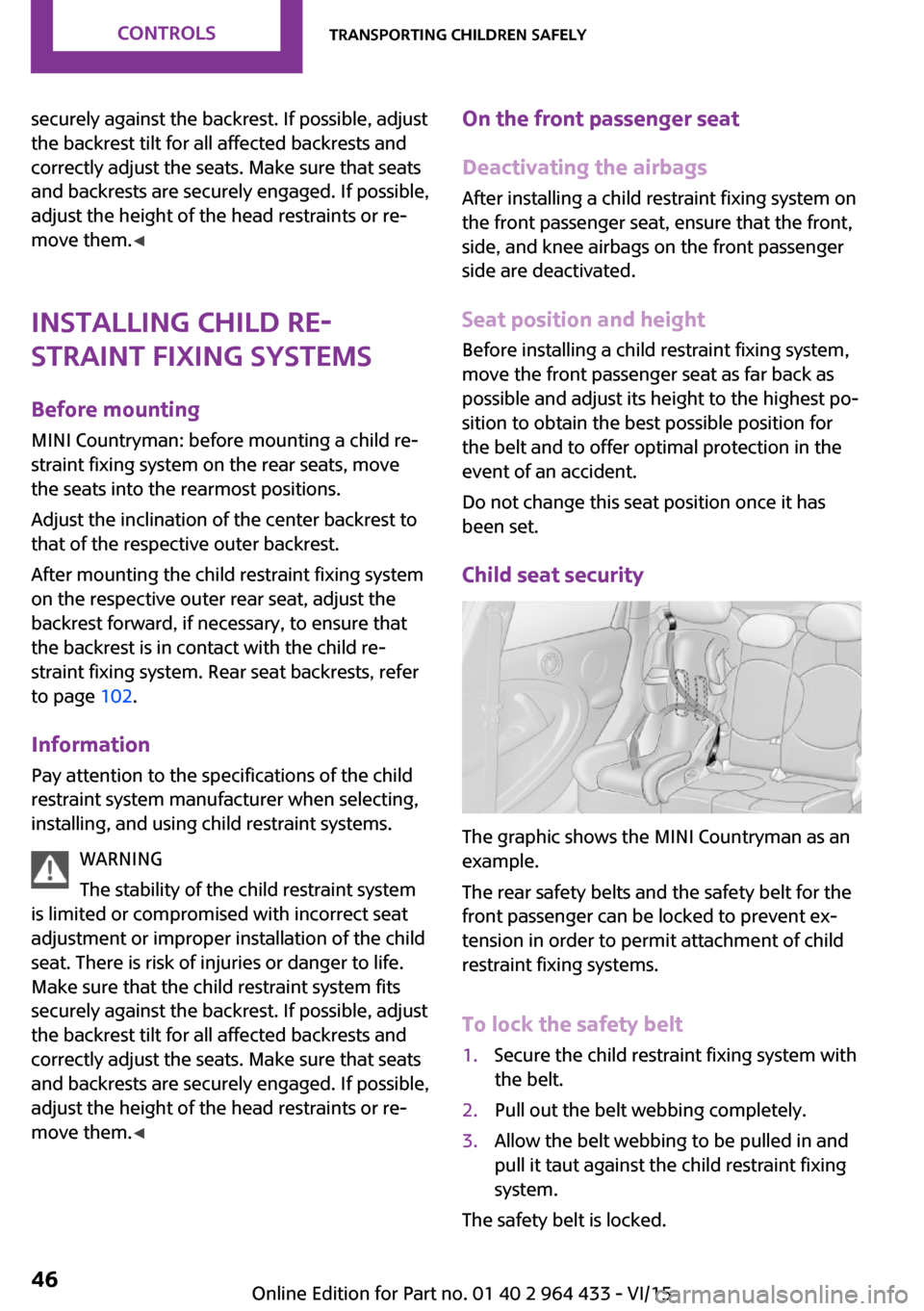
The graphic shows the MINI Countryman as an
example.
The rear safety belts and the safety belt for the
front passenger can be locked to prevent ex‐
tension in order to permit attachment of child
restraint fixing systems.
To lock the safety belt
1.Secure the child restraint fixing system with
the belt.2.Pull out the belt webbing completely.3.Allow the belt webbing to be pulled in and
pull it taut against the child restraint fixing
system.
The safety belt is locked.
Seite 46CONTROLSTransporting children safely46
Online Edition for Part no. 01 40 2 964 433 - VI/15