check engine light MITSUBISHI 3000GT 1991 User Guide
[x] Cancel search | Manufacturer: MITSUBISHI, Model Year: 1991, Model line: 3000GT, Model: MITSUBISHI 3000GT 1991Pages: 1146, PDF Size: 76.68 MB
Page 137 of 1146
SERVICE ADJUSTMENT PROCEDURES
MlBFHSU
BASIC IDLE SPEED ADJUSTMENT
NOTE(1) The basic idle speed has been factory-adjusted with the
speed adjusting screw (SAS) and does not normally require
adjustment.(2) If the adjustment is required, first check that the ignition
plug, injector,
ISC servo, and compression pressure are
normal.
(1) Before starting the inspection and adjustment procedures,set the vehicle in the following conditions:
l
Engine coolant temperature: 80 to 95°C (176 to 205°F)l Lights, electric cooling fan, accessories: OFF
lTransaxle: Neutral (P range on vehicles with automatic
transaxle)l Steering wheel: Straightforward position
(2) When using the multi-use tester, connect it to the diagnosis
connector.
NOTEThe connection of the multi-use tester grounds the
self-
diagnosis/data transmission selector terminal.
(3) When not using the multi-use tester, proceed as follows:
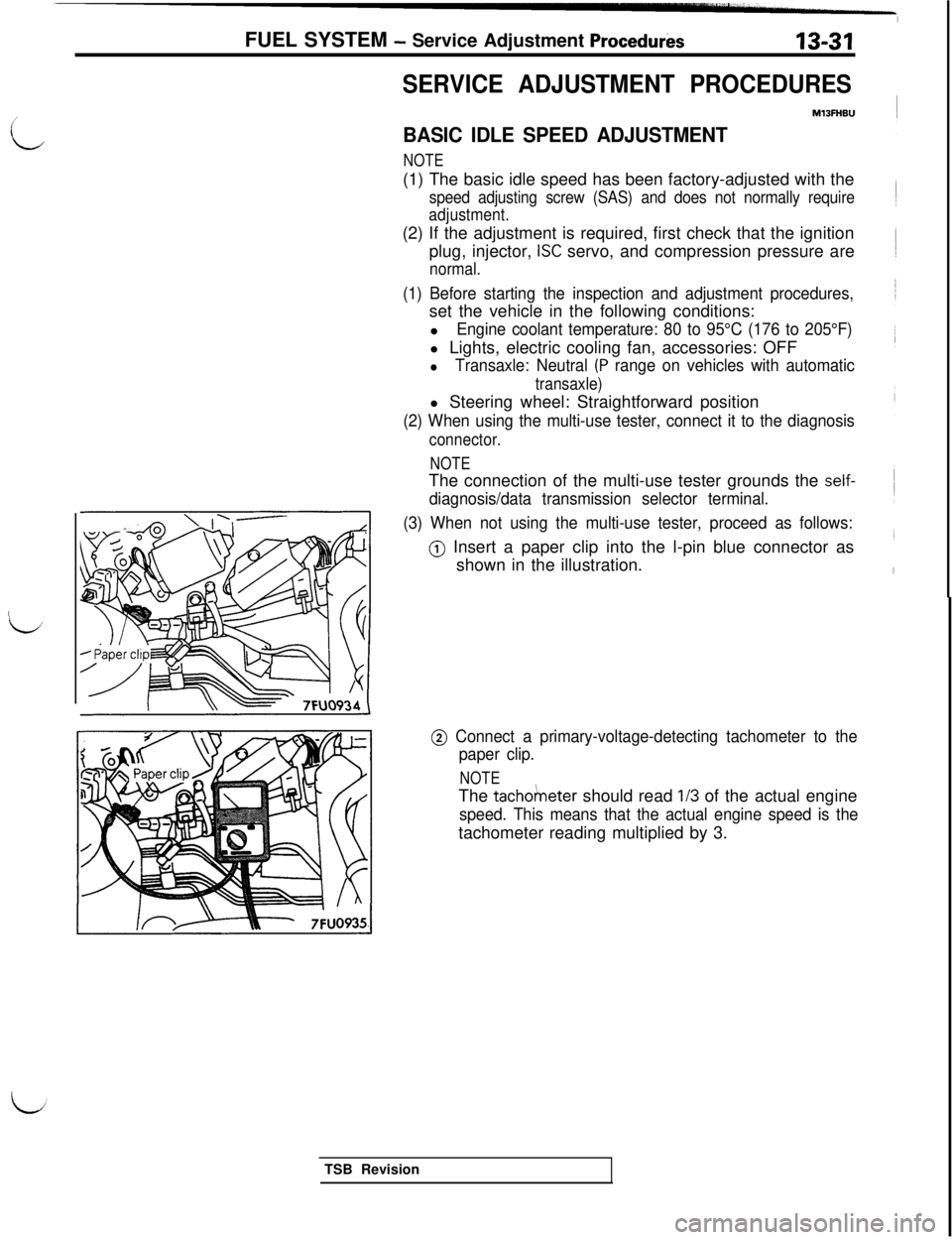
@) Insert a paper clip into the l-pin blue connector as
shown in the illustration. FUEL SYSTEM
- Service Adjustment Procedurks13-31
i
@ Connect a primary-voltage-detecting tachometer to the
paper clip.
NOTEThe
tacho/neter should read l/3 of the actual engine
speed. This means that the actual engine speed is thetachometer reading multiplied by 3.
TSB Revision
Page 161 of 1146
FUEL SYSTEM - On-vehicle Inspection of MPI Components13-55
INSPECTIONUsing Multi-use Tester
Function
Data readingtern No. Data display
12Sensor airvolume(frequency)
Check conditionEngine stateStandard value
l Engine coolant tem-
700 rpm (Idle)25-50 Hzperature: 80 to 95°C
(176 to 205°F)2,000 rpm70-IOOHzl Lights and accessories:OFFRacingFrequency increasesl Transaxle: Neutralwith racing(P range for vehiclewith AIT)l Steering wheel: Neutral
NOTEWhen the vehicle is new [within initial operation of about 500 km (300 miles)], the air flow sensor output frequency maybe about 10% higher.
Function
Data listItem No. Data displayCheck conditionsEngine conditionsStandard value
34Reset signall Engine warm up700 rpm (Idle)ON
condition2,000 rpmOFF
L;
FunctionItem No. Data display
Data list37Volumetric
efficiencyCheck conditionEngine stateStandard valuel Engine coolant tem-700 rpm (Idle)20-35%
perature: 80 to 95°C
(176 to 205°F)
l Lights, electric cooling2,000 rpm15-30%
fan and accessory opera-tion: OFFl Transaxle: NeutralRacingFrequency increases
(P range for vehiclewith racingwith &T)
l Steering wheel: Neutral
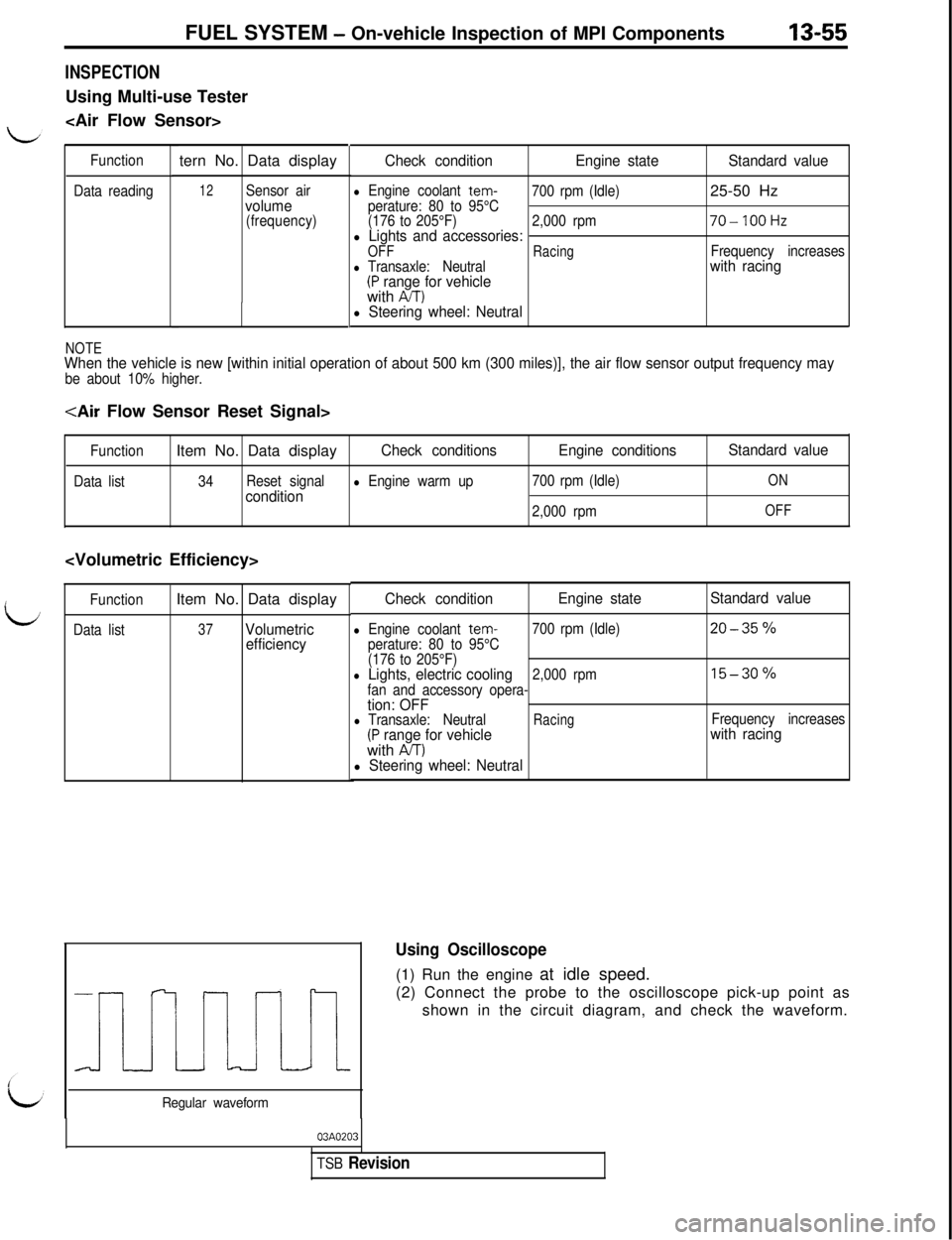
Using Oscilloscope(1) Run the engine at idle speed.
(2) Connect the probe to the oscilloscope pick-up point as
shown in the circuit diagram, and check the waveform.
Regular waveform
03A0203
TSB Revision
Page 192 of 1146
13-86FUEL SYSTEM - On-vehicle Inspection of MPI Components
ELECTRICAL LOAD SWITCH16FO29;
Tail-lightrelayDefog.wrelaystoplight
t;1
switch
ti* . .
Engine control unit connector
Engine
control
unit7FUO653
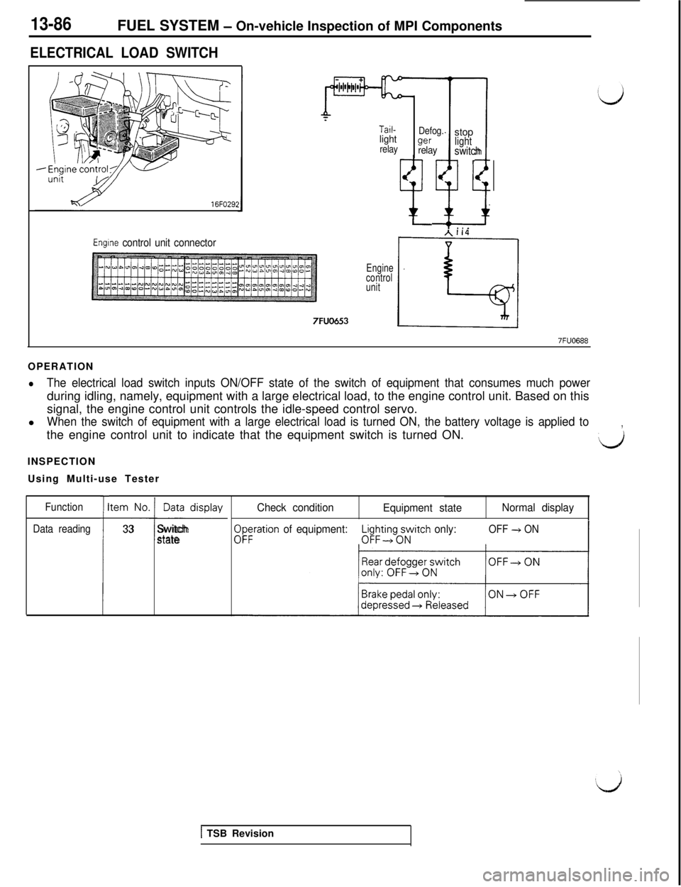
7FUO688OPERATION
lThe electrical load switch inputs ON/OFF state of the switch of equipment that consumes much powerduring idling, namely, equipment with a large electrical load, to the engine control unit. Based on this
signal, the engine control unit controls the idle-speed control servo.
l
When the switch of equipment with a large electrical load is turned ON, the battery voltage is applied tothe engine control unit to indicate that the equipment switch is turned ON.,
LJINSPECTION
Using Multi-use Tester
Function
Data reading
I
tem No. Data display
-I-
33Switchstate
Check condition
Equipment stateNormal display
$;ration of equipment:L$ing;Atch only:OFF + ON-3
1 TSB Revision
Page 193 of 1146
FUEL SYSTEM - On-vehicle InsDection of MPI ComDonents
/
idHARNESS INSPECTION
Engine control
unit harness
side connector7FUO689
side connector7FuO689
PU
Engine control
unit harness
side connectorT7FUO689
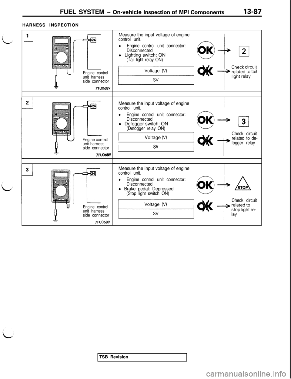
Measure the input voltage of engineIcontrol unit.
lEngine control unit connector:
Disconnectedl Lighting switch: ON
(Tail light relay ON)
Measure the input voltage of enginecontrol unit.
lEngine control unit connector:
Disconnectedl Defogger switch: ON
(Defogger relay ON)Voltage
(V)
Isv
cl3
Check circuit
related to de-
fogger relay
Measure the input voltage of enginecontrol unit.
lEngine control unit connector:
Disconnected
l Brake pedal: Depressed(Stop light switch ON)
Check circuitTSB Revision
Page 222 of 1146
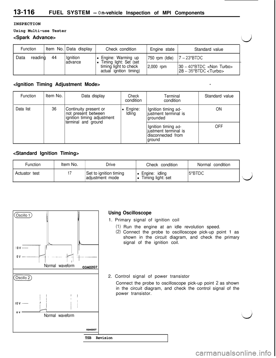
13-116FUEL SYSTEM - 0
n-vehicle Inspection of MPI Components
INSPECTION
Using Multi-use Tester
(d
FunctionItem No. Data displayCheck condition
Engine state
Standard valueData reading 44
Ignitionadvancel Engine: Warming up
750 rpm (Idle)7 - 23”BTDCl Timing light: Set (settiming light to check2,000 rpm30 - 40”BTDC
‘
Function
Data listItem No.Data displayCheckTerminalStandard value
condition
condition
36Continuity present or
not present betweenl Engine:
IdlingIgnition timing ad-ON
ignition timing adjustmentjustment terminal isterminal and groundgrounded
Ignition timing ad-OFFjustment terminal is
disconnected from
ground
Function
Actuator testItem No.
DriveCheck conditionNormal condition
17Set to ignition timingl Engine: idling5”BTDCadjustment model Timing light: set\
($Gizi)
IJ
\LIOV _
ovep~,. ..~_~.~ fA t---.-
I
Normal waveform03AO207
(
j /’ II
IOV _I ’/
/ 1ovIJ
Normal waveform
Using Oscilloscope1. Primary signal of ignition coil
(I) Run the engine at an idle revolution speed.
(2) Connect the probe to oscilloscope pick-up point 1 as
shown in the circuit diagram, and check the primary
signal of the ignition coil.
2. Control signal of power transistor
Connect the probe to oscilloscope pick-up point
2 as shown
in the circuit diagram, and check the control signal of the
power transistor.
TSB Revision
Page 246 of 1146
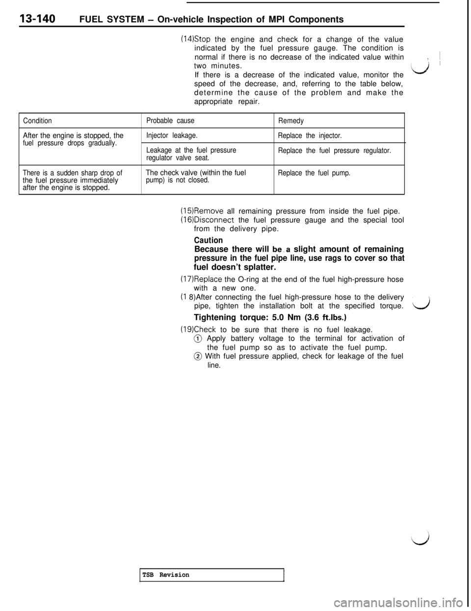
13-140FUEL SYSTEM - On-vehicle Inspection of MPI Components
(14)Stop the engine and check for a change of the value
indicated by the fuel pressure gauge. The condition is
normal if there is no decrease of the indicated value within~
two minutes.
,If there is a decrease of the indicated value, monitor the
:d ’speed of the decrease, and, referring to the table below,
determine the cause of the problem and make the
appropriate repair.
Condition
After the engine is stopped, thefuel pressure drops gradually.Probable cause
Injector leakage.
Leakage at the fuel pressure
regulator valve seat.Remedy
Replace the injector.
Replace the fuel pressure regulator.
There is a sudden sharp drop of
the fuel pressure immediately
after the engine is stopped.The check valve (within the fuelpump) is not closed.Replace the fuel pump.
(15)Remove all remaining pressure from inside the fuel pipe.(16)Disconnect the fuel pressure gauge and the special tool
from the delivery pipe.
CautionBecause there will be.a slight amount of remaining
pressure in the fuel pipe line, use rags to cover so thatfuel doesn’t splatter.
(17)Replace the O-ring at the end of the fuel high-pressure hose
with a new one.(I 8)After connecting the fuel high-pressure hose to the delivery
pipe, tighten the installation bolt at the specified torque.
dTightening torque: 5.0 Nm (3.6 ftlbs.)
(19)Check to be sure that there is no fuel leakage.@ Apply battery voltage to the terminal for activation of
the fuel pump so as to activate the fuel pump.@ With fuel pressure applied, check for leakage of the fuel
line.
TSB Revision
Page 262 of 1146
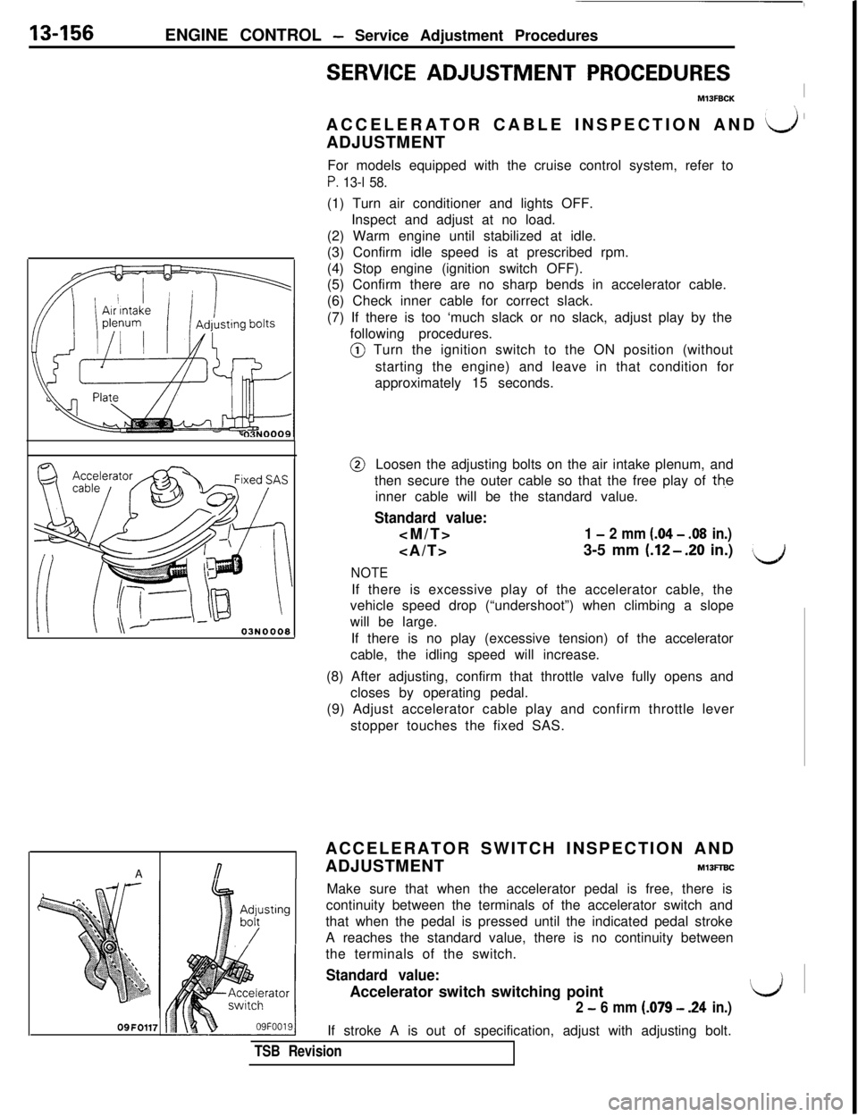
13-156ENGINE CONTROL - Service Adjustment Procedures
SERVICE ADJUSTMENT PROCEDURES
M13FBCKIACCELERATOR CABLE INSPECTION AND
a ’ADJUSTMENT
For models equipped with the cruise control system, refer to
P. 13-l 58.(1) Turn air conditioner and lights OFF.
Inspect and adjust at no load.
(2) Warm engine until stabilized at idle.
(3) Confirm idle speed is at prescribed rpm.
(4) Stop engine (ignition switch OFF).
(5) Confirm there are no sharp bends in accelerator cable.
(6) Check inner cable for correct slack.
(7) If there is too ‘much slack or no slack, adjust play by the
following procedures.@ Turn the ignition switch to the ON position (without
starting the engine) and leave in that condition for
approximately 15 seconds.@Loosen the adjusting bolts on the air intake plenum, and
then secure the outer cable so that the free play of
th,einner cable will be the standard value.
Standard value:
1 - 2 mm (.04 - .08 in.)3-5 mm
(.12-.20 in.)
NOTE
\JIf there is excessive play of the accelerator cable, the
vehicle speed drop (“undershoot”) when climbing a slope
will be large.
If there is no play (excessive tension) of the accelerator
cable, the idling speed will increase.
(8) After adjusting, confirm that throttle valve fully opens and
closes by operating pedal.
(9) Adjust accelerator cable play and confirm throttle lever
stopper touches the fixed SAS.
ACCELERATOR SWITCH INSPECTION AND
A
nADJUSTMENTMlBFlBC
09FO117Make sure that when the accelerator pedal is free, there is
;$ustingcontinuity between the terminals of the accelerator switch and
/that when the pedal is pressed until the indicated pedal stroke
A reaches the standard value, there is no continuity between
the terminals of the switch.
Standard value:Accelerator switch switching point
2 - 6 mm (.079 - .24 in.)If stroke A is out of specification, adjust with adjusting bolt.
TSB Revision
\
‘LJ ~
Page 284 of 1146
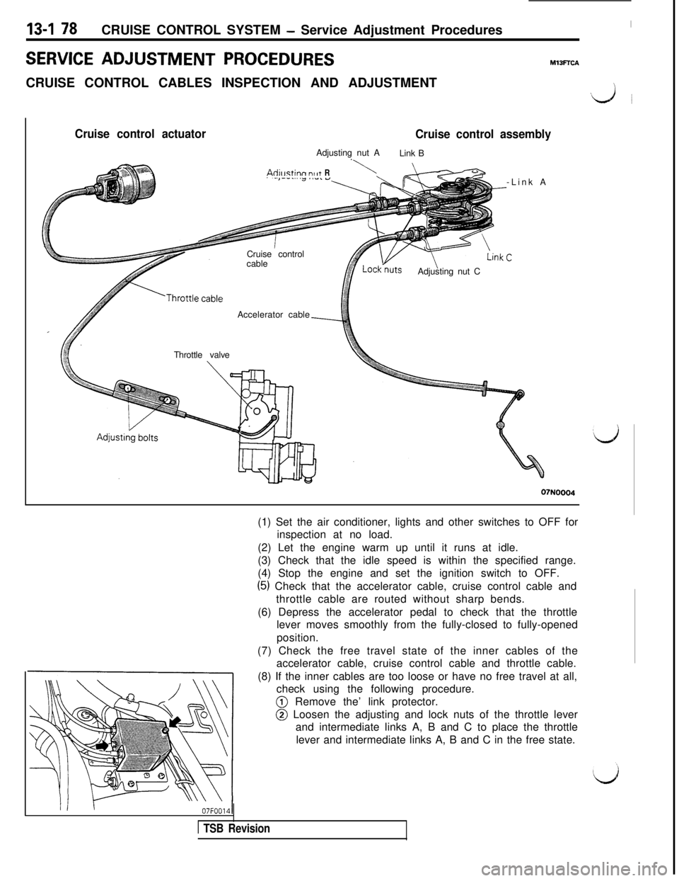
13-I 78CRUISE CONTROL SYSTEM - Service Adjustment ProceduresSERVICE
ADJUSTMENT PROCEDURESCRUISE CONTROL CABLES INSPECTION AND ADJUSTMENT
I
MlSFTCA
‘\J ~
Cruise control actuator
Cruise control assemblyAdjusting nut A
Link B
.
Adillstinn nr~+ R\Cruise control
cable
Adjusting nut C
Accelerator cable
Throttle valve-Link A
07N0004(1) Set the air conditioner, lights and other switches to OFF for
inspection at no load.
(2) Let the engine warm up until it runs at idle.
(3) Check that the idle speed is within the specified range.
(4) Stop the engine and set the ignition switch to OFF.
(5) Check that the accelerator cable, cruise control cable and
throttle cable are routed without sharp bends.
(6) Depress the accelerator pedal to check that the throttle
lever moves smoothly from the fully-closed to fully-opened
position.
(7) Check the free travel state of the inner cables of the
accelerator cable, cruise control cable and throttle cable.
(8) If the inner cables are too loose or have no free travel at all,
check using the following procedure.@ Remove the’ link protector.
@ Loosen the adjusting and lock nuts of the throttle lever
and intermediate links A, B and C to place the throttle
lever and intermediate links A, B and C in the free state.
1 TSB Revision
Page 285 of 1146
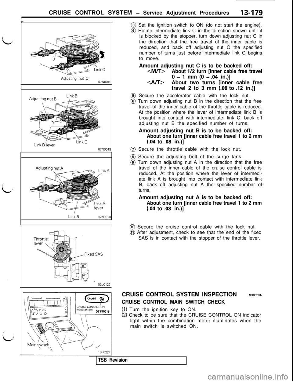
CRUISE CONTROL SYSTEM - Service Adjustment Procedures13-179Adjusting nut C
07NOOlELink Blever
07N0019Link
B07NOOlE
y,jj--ww ,03LO122
\\ \18FO2.2'@ Set the ignition switch to ON (do not start the engine).@ Rotate intermediate link C in the direction shown until it
is blocked by the stopper, turn down adjusting nut C in
the direction that the free travel of the inner cable is
reduced, and back off adjusting nut C the specified
number of turns just before intermediate link C begins
to move.
Amount adjusting nut C is to be backed off:
- 1 mm (0 - .04 in.)]
About two turns [inner cable free
travel 2 to 3 mm
(.08 to .12 in.)]@ Secure the accelerator cable with the lock nut.@ Turn down adjusting nut B in the direction that the free
travel of the inner cable of the throttle cable is reduced.
At the position where the lever of intermediate link B is
brought into contact with intermediate. link C, back off
adjusting nut B the specified number of turns.
Amount adjusting nut B is to be backed off:
About one turn [inner cable free travel 1 to 2 mm
(.04 to .08 in.)]@ Secure the throttle cable with the lock nut.@ Secure the adjusting bolt of the surge tank.@ Turn down adjusting nut A in the direction that the free
travel of the inner cable of the cruise control cable is
reduced. At the position where the lever of intermedi-
ate link A is brought into contact with intermediate link
B, back off adjusting nut A the specified number of
turns.
Amount adjusting nut A is to be backed off:
About one turn [inner cable free travel 1 to 2 mm
(.04 to .08 in.)]@ Secure the cruise control cable with the lock nut.@ After adjustment, check to see that the end of the fixed
SAS is in contact with the stopper of the throttle lever.
CRUISE CONTROL SYSTEM INSPECTION
MlBFlDA
CRUISE CONTROL MAIN SWITCH CHECK
(1) Turn the ignition key to ON.
(2) Check to be sure that the CRUISE CONTROL ON indicator
light within the combination meter illuminates when the
main switch is switched ON.
TSB Revision
Page 353 of 1146
EMISSION CONTROL - EvaporativeEmission Control System
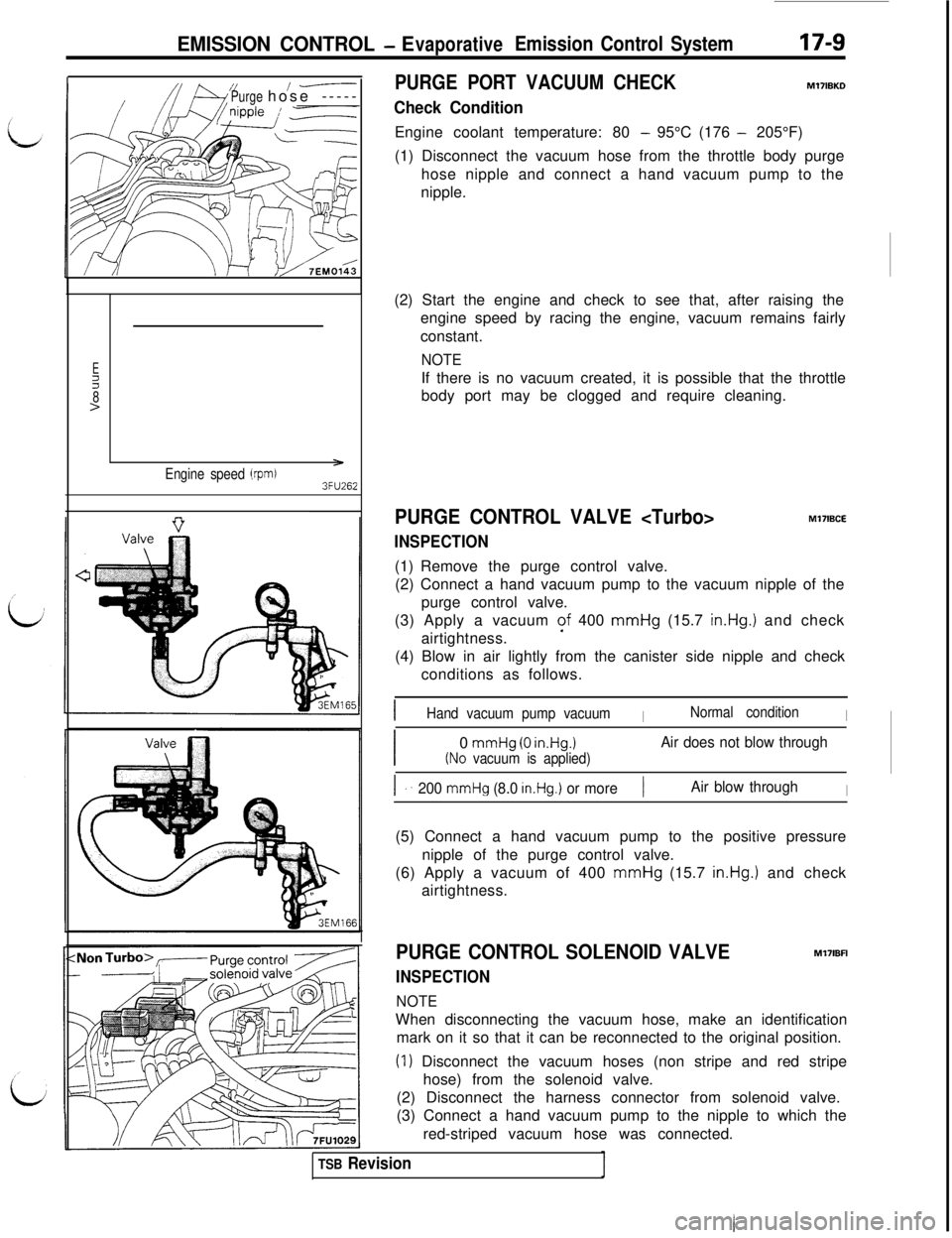
Purge/-----hose -----PURGE PORT VACUUM CHECK
Check Condition
17-9
M17lBKDEngine coolant temperature: 80
- 95°C (176 - 205°F)
(1) Disconnect the vacuum hose from the throttle body purge
hose nipple and connect a hand vacuum pump to the
nipple.
Ez8>
Engine speed (rprd3FU262(2) Start the engine and check to see that, after raising the
engine speed by racing the engine, vacuum remains fairly
constant.
NOTEIf there is no vacuum created, it is possible that the throttle
body port may be clogged and require cleaning.
PURGE CONTROL VALVE
INSPECTIONMl7IBCE
(1) Remove the purge control valve.
(2) Connect a hand vacuum pump to the vacuum nipple of the
purge control valve.
(3) Apply a vacuum of 400 mmHg (15.7
in.Hg.1 and check
airtightness.
(4) Blow in air lightly from the canister side nipple and check
conditions as follows.
IHand vacuum pump vacuumINormal conditionI
I0
mmHg (0 in.Hg.1Air does not blow through
(No vacuum is applied)
I ..200 mmHg (8.0 in.Hg.) or more1Air blow throughI(5) Connect a hand vacuum pump to the positive pressure
nipple of the purge control valve.
(6) Apply a vacuum of 400 mmHg (15.7
in.Hg.1 and check
airtightness.
PURGE CONTROL SOLENOID VALVE
INSPECTION
NOTEMl7lBFI
When disconnecting the vacuum hose, make an identification
mark on it so that it can be reconnected to the original position.
(I) Disconnect the vacuum hoses (non stripe and red stripe
hose) from the solenoid valve.
(2) Disconnect the harness connector from solenoid valve.
(3) Connect a hand vacuum pump to the nipple to which the
red-striped vacuum hose was connected.
TSB Revision