check engine light MITSUBISHI 3000GT 1991 Owner's Guide
[x] Cancel search | Manufacturer: MITSUBISHI, Model Year: 1991, Model line: 3000GT, Model: MITSUBISHI 3000GT 1991Pages: 1146, PDF Size: 76.68 MB
Page 767 of 1146
SERVICE BRAKES - Set-vice Adiustment Procedures35-45lUF51F
Pedal
7\ \!4FOO7.
F14511
F14519
TSB Revision-_.1
SERVICE ADJUSTMENT PROCEDURES
BRAKE PEDAL INSPECTION AND ADJUSTMENT
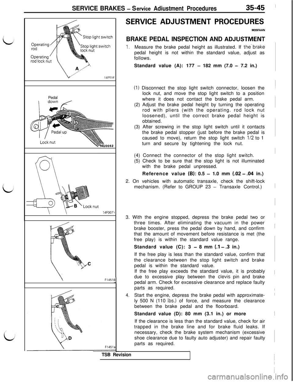
1.Measure the brake pedal height as illustrated. If the’brakepedal height is not within the standard value, adjust as
follows.
Standard value (A): 177
- 182 mm (7.0 - 7.2 in.)
(I) Disconnect the stop light switch connector, loosen the
lock nut, and move the stop light switch to a position
where it does not contact the brake pedal arm.
(2) Adjust the brake pedal height by turning the operating
rod with pliers (with the operating. rod lock nut
loosened), until the correct brake pedal height is
obtained.
(3) After screwing in the stop light switch until it contacts
the brake pedal stopper (just before the brake pedal is
caused to move), return the stop light switch
l/2 to 1
turn and secure by tightening the lock nut.
(4) Connect the connector of the stop light switch.
(5) Check to be sure that the stop light is not illuminated
with the brake pedal unpressed.
Reference value (6): 0.5
- 1.0 mm (.02 - .04 in.)
2. On vehicles with automatic transaxle, check the shift-lock
mechanism. (Refer to GROUP 23
- Transaxle Control.)
3. With the engine stopped, depress the brake pedal two or
three times. After eliminating the vacuum in the power
brake booster, press the pedal down by hand, and confirm
that the amount of movement before resistance is met (the
free play) is within the standard value range.
Standard value (C): 3
- 8 mm (.I - .3 in.)
If the free play is less than the standard value, confirm that
the clearance between the stop light switch and brake
pedal is within the standard value.
If the free play exceeds the standard value, it is probably
due to excessive play between the clevis pin and brake
pedal arm. Check for excessive clearance and replace faulty
parts as required.
4.Start the engine, depress the brake pedal with approximate-
ly 500 N (110
Ibs.) of force, and measure the clearance
between the brake pedal and the floorboard.
Standard value (D): 80 mm (3.1 in.) or more
If the clearance is less than the standard value, check for air
trapped in the brake line and for brake fluid leaks. If
necessary, check the brake system mechanism (excessive
shoe clearance due to faulty auto adjuster) and repair faulty
parts as required.~1~1
I
I
I
I
I
Page 768 of 1146
35-46SERVICE BRAKES - Service Adjustment Procedures
BRAKE FLUID LEVEL SENSOR CHECK
I
MBSFBAF
Good
k‘14UOO61
When engine is
stoppedNo good
When engine isstarted
14UOO6C)Checkvalve/1. Connect a circuit tester to the brake fluid level sensor.
I
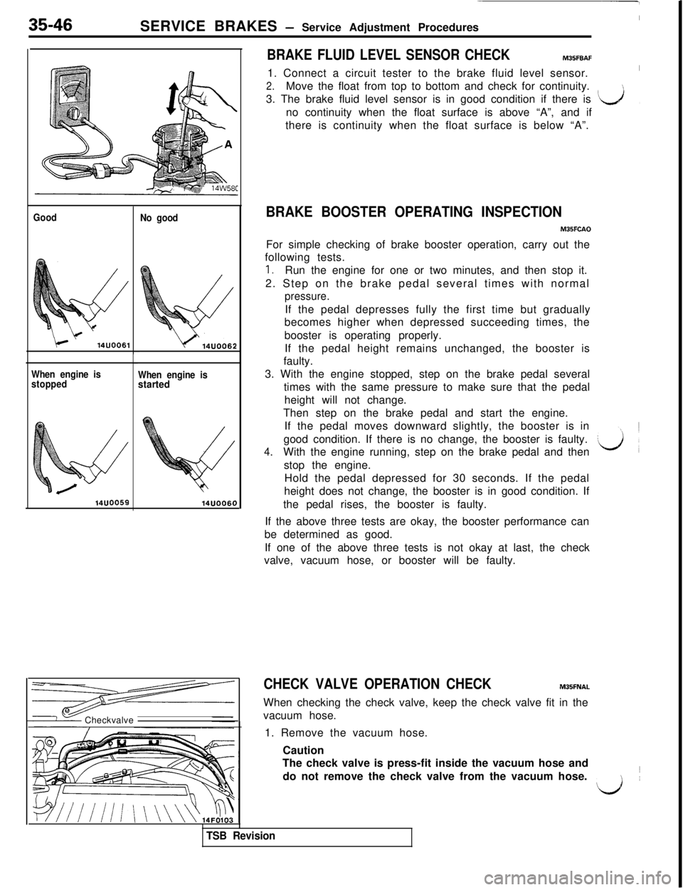
2.Move the float from top to bottom and check for continuity.
3. The brake fluid level sensor is in good condition if there is
‘k&Jno continuity when the float surface is above “A”, and if,there is continuity when the float surface is below “A”.
BRAKE BOOSTER OPERATING INSPECTION
M35FCAOFor simple checking of brake booster operation, carry out the
following tests.
1.Run the engine for one or two minutes, and then stop it.
2. Step on the brake pedal several times with normal
pressure.If the pedal depresses fully the first time but gradually
becomes higher when depressed succeeding times, the
booster is operating properly.
If the pedal height remains unchanged, the booster is
faulty.
3. With the engine stopped, step on the brake pedal several
times with the same pressure to make sure that the pedal
height will not change.
Then step on the brake pedal and start the engine.
If the pedal moves downward slightly, the booster is in
good condition. If there is no change, the booster is faulty.
4.With the engine running, step on the brake pedal and then
stop the engine.
Hold the pedal depressed for 30 seconds. If the pedal
height does not change, the booster is in good condition. If
the pedal rises, the booster is faulty.
If the above three tests are okay, the booster performance can
be determined as good.
If one of the above three tests is not okay at last, the check
valve, vacuum hose, or booster will be faulty.
CHECK VALVE OPERATION CHECKM35FNALWhen checking the check valve, keep the check valve fit in the
vacuum hose.
1. Remove the vacuum hose.
Caution
The check valve is press-fit inside the vacuum hose and
do not remove the check valve from the vacuum hose.1
d~
TSB Revision
Page 780 of 1146
35-58SERVICE BRAKES - Service Adjustment Procedures
POINTS IN WAVEFORM MEASUREMENT
Symptom
Too small or zero waveform
amplitudeProbable causes
Faulty wheel speed sensorRemedy
Replace sensor
Incorrect pole piece-to-rotor clearance
Adjust clearance
Waveform amplitude fluctuates
excessively (this is no problem ifAxle hub eccentric or with large runout
Replace hub
the minimum amplitude is
100 mV
or more)
Noisy or disturbed waveformOpen circuit in sensor
Open circuit in harness
Incorrectly mounted wheel speed sensor
Rotor with missing or damaged teethReplace sensor
Correct harness
Mount correctly
Replace rotor
NOTEThe wheel speed sensor cable moves following motion of the front or rear suspension. Therefore, it is likely that it has an
open circuit only when driving on rough roads and it functions normally on ordinary roads. It is, therefore, recommended
to observe sensor output voltage waveform also under special conditions, such as rough road driving,
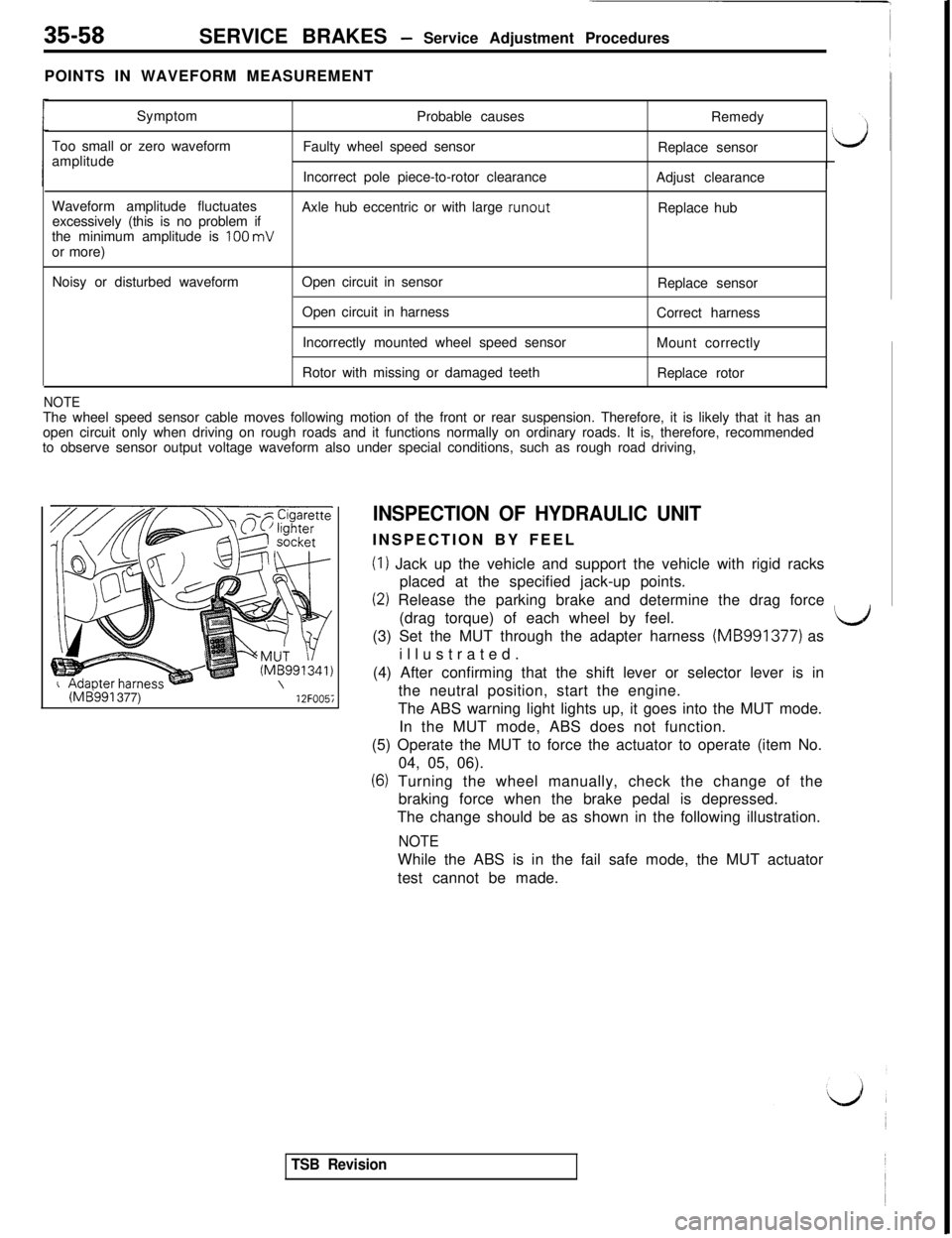
(ME!991 377)12FOO5i
INSPECTION OF HYDRAULIC UNITINSPECTION BY FEEL
(I) Jack up the vehicle and support the vehicle with rigid racks
placed at the specified jack-up points.
(2) Release the parking brake and determine the drag force
(drag torque) of each wheel by feel.
LJ(3) Set the MUT through the adapter harness (MB991377) as
illustrated.
(4) After confirming that the shift lever or selector lever is in
the neutral position, start the engine.
The ABS warning light lights up, it goes into the MUT mode.
In the MUT mode, ABS does not function.
(5) Operate the MUT to force the actuator to operate (item No.
04, 05, 06).
(6) Turning the wheel manually, check the change of the
braking force when the brake pedal is depressed.
The change should be as shown in the following illustration.
NOTEWhile the ABS is in the fail safe mode, the MUT actuator
test cannot be made.
TSB Revision
Page 784 of 1146
When energized
Between terminals 4 and 5Continuity
When de-energized
Between terminals 4 and 5\i fl \\ 16FO264No continuity
Between terminals 1 and 3Continuity
16FO122L--J18FOCII
SERVICE BRAKES - Service Adjustment ProceduresI
INSPECTION OF POWER RELAYM35FOAP
7
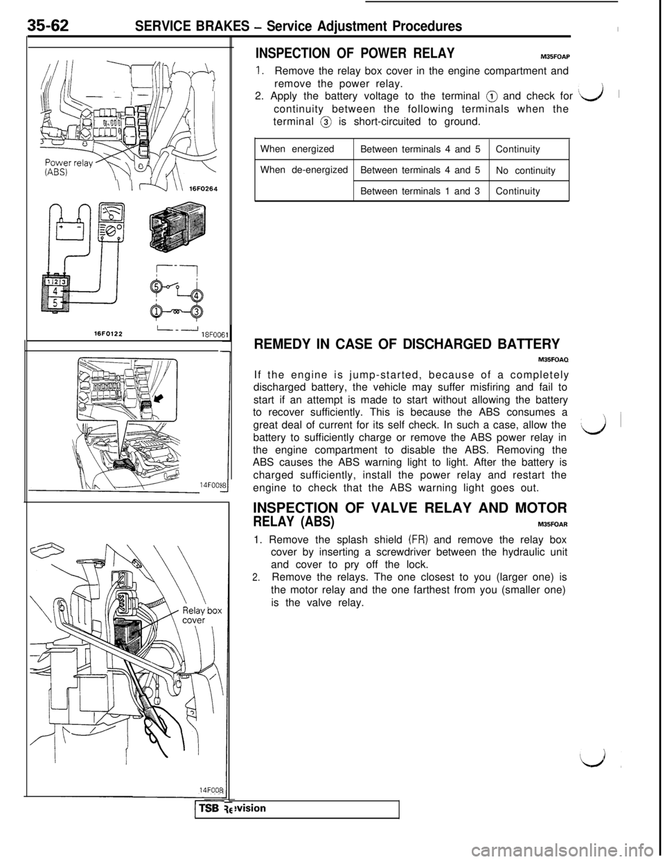
1.Remove the relay box cover in the engine compartment and
remove the power relay.
2. Apply the battery voltage to the terminal @ and check for
‘L-J1
continuity between the following terminals when the
terminal @ is short-circuited to ground.
35-62
14FOOS14FOO8
l-TSB
1
REMEDY IN CASE OF DISCHARGED BATTERY
M35FOAQIf the engine is jump-started, because of a completely
discharged battery, the vehicle may suffer misfiring and fail to
start if an attempt is made to start without allowing the battery
to recover sufficiently. This is because the ABS consumes a
great deal of current for its self check. In such a case, allow the
battery to sufficiently charge or remove the ABS power relay in
the engine compartment to disable the ABS. Removing the
ABS causes the ABS warning light to light. After the battery is
charged sufficiently, install the power relay and restart the
engine to check that the ABS warning light goes out.
INSPECTION OF VALVE RELAY AND MOTOR
RELAY (ABS)M35FOAR1. Remove the splash shield
(FR) and remove the relay box
cover by inserting a screwdriver between the hydraulic unit
and cover to pry off the lock.
2.Remove the relays. The one closest to you (larger one) is
the motor relay and the one farthest from you (smaller one)
is the valve relay.
‘d~ i
wision
Page 833 of 1146
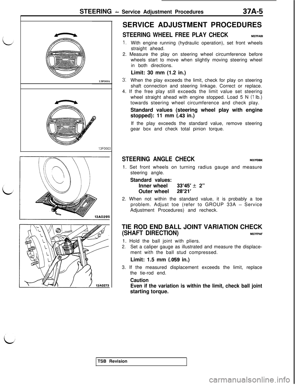
STEERING 2 Service Adjustment Procedures37A-5
13FOOOi13FOOO3SERVICE ADJUSTMENT PROCEDURES
STEERING WHEEL FREE PLAY CHECKM37FABI
1.With engine running (hydraulic operation), set front wheels
straight ahead.
2. Measure the play on steering wheel circumference before
wheels start to move when slightly moving steering wheel
in both directions.
Limit: 30 mm (1.2 in.)
3:When the play exceeds the limit, check for play on steering
shaft connection and steering linkage. Correct or replace.
4. If the free play still exceeds the limit value set steering
wheel straight ahead with engine stopped. Load 5 N
(1 lb.)
towards steering wheel circumference and check play.
Standard values (steering wheel play with engine
stopped): 11 mm
(.43 in.)
If the play exceeds the standard value, remove steering
gear box and check total pinion torque.
STEERING ANGLE CHECKM37FDBK1. Set front wheels on turning radius gauge and measure
steering angle.
Standard values:Inner wheel
33”45’ k 2”
Outer wheel
28”21’2. When not within the standard value, it is probably a toe
problem. Adjust toe (refer to GROUP 33A
- Service
Adjustment Procedures) and recheck.
TIE ROD END BALL JOINT VARIATION CHECK
(SHAFT DIRECTION)M37FPAF1. Hold the ball joint with pliers.
2.Set a caliper gauge as illustrated and measure the displace-
ment with the ball stud compressed.
Limit: 1.5 mm
(.059 in.)
3. If the measured displacement exceeds the limit, replace
the tie-rod end.
Caution
Even if the variation is within the limit, check ball jointstarting torque.
TSB Revision
Page 873 of 1146
42-1
BODY
CONTENTSM42AA- -
CENTER PILLAR GLASS........................................................32
CENTRAL DOOR LOCKING SYSTEM
................................55
DOOR ASSEMBLY....................................................................40
DOOR GLASS AND REGULATOR
........................................42
DOOR HANDLE AND LATCH
................................................54
DOOR TRIM AND WATERPROOF FILM
............................41
DRIP LINE WEATHERSTRIP....................................................65
ENGINE HOOD........................................................................18
FENDER*....................................................................................23
FUEL TANK FILLER DOOR
....................................................22
LIFTGATE....................................................................................20
LIFTGATE GLASS....................................................................37
LOOSE PANEL
........................................................................24
POWER WINDOW
....................................................................43
QUARTER WINDOW GLASS
................................................33SERVICE ADJUSTMENT PROCEDURES
............................
Door Adjustment................................................................Door inside Handle Play Check............................................Door Window Glass Adjustment........................................Floor Pan inspection............................................................Fuel Filler Door Adjustment................................................Hood Adjustment................................................................Liftgate Adjustment............................................................
SPECIAL TOOLS........................................................................
SPECIFICATIONS....................................................................
General Specifications........................................................Sealants and Adhesives........................................................
ServiceSpecifications........................................................
TROUBLESHOOTING............................................................
WINDOW GLASS....................................................................
WINDSHIELD............................................................................
13
14
16
14
17
14
13
13
4
2
2
3
3
5
25
28
SUPPLEMENTAL RESTRAINT SYSTEM (SRS)
(1)A Supplemental Restraint System (SRS), which uses a driver-side air bag, has been installed in the 3000GT.(2)The SRS includes the following components: impact sensors, SRS diagnosis unit: SRS warning light, air bagmodule, clock spring, interconnecting wiring. Other SRS-related components (that may have to be
removed/installed in connection with SRS service or maintenance) are indicated in the table of contents byan asterisk (*).
WARNING!(1)Improper service or maintenance of any component of the SRS, or any SRS-related component, can lead to
personal injury or death to service personnel (from inadvertent firing of the air bag) or to the driver (from
rendering the SRS inoperative).
(2) Service or maintenance of any SRS component or SRS-related component must be performed only at an
authorized MITSUBISHI dealer.(3) MITSUBISHI dealer personnel must thoroughly review this manual, and especially its GROUP 52B
-Supplemental Restraint System (SRS), before beginning any service or maintenance of any component of the
SRS or any SRS-related component.
Page 891 of 1146
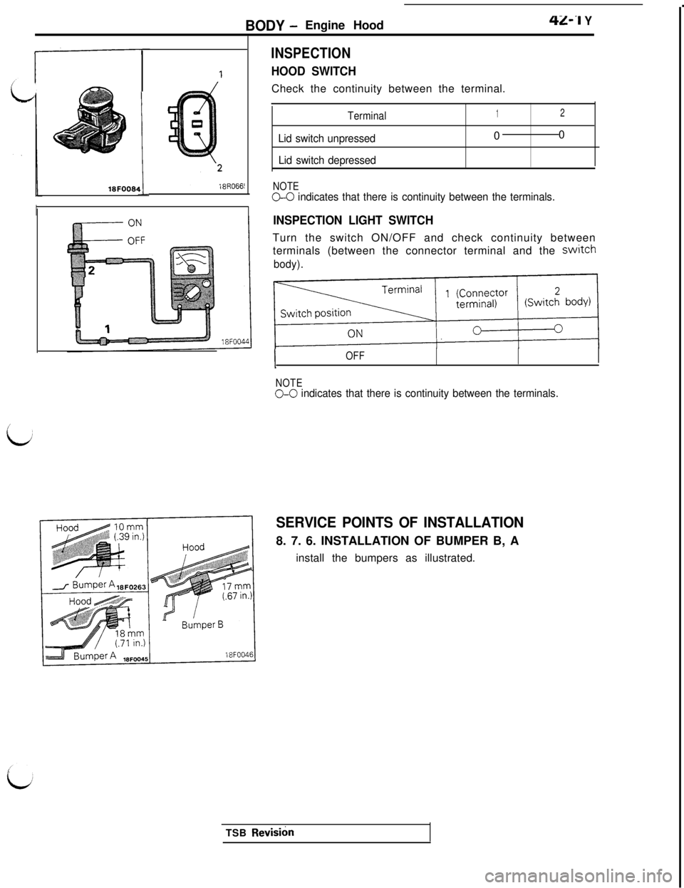
BODY -Engine Hood42-I Y18FOOW
!I
II
INSPECTION
HOOD SWITCHCheck the continuity between the terminal.
Terminal
Lid switch unpressed
Lid switch depressed
1200
NOTEG-0 indicates that there is continuity between the terminals.
INSPECTION LIGHT SWITCHTurn the switch ON/OFF and check continuity between
terminals (between the connector terminal and the
switch
body).
IOFF
NOTE
O-0 indicates that there is continuity between the terminals.
t
SERVICE POINTS OF INSTALLATION8. 7. 6. INSTALLATION OF BUMPER B, A
install the bumpers as illustrated.
TSB
Revish
Page 1027 of 1146
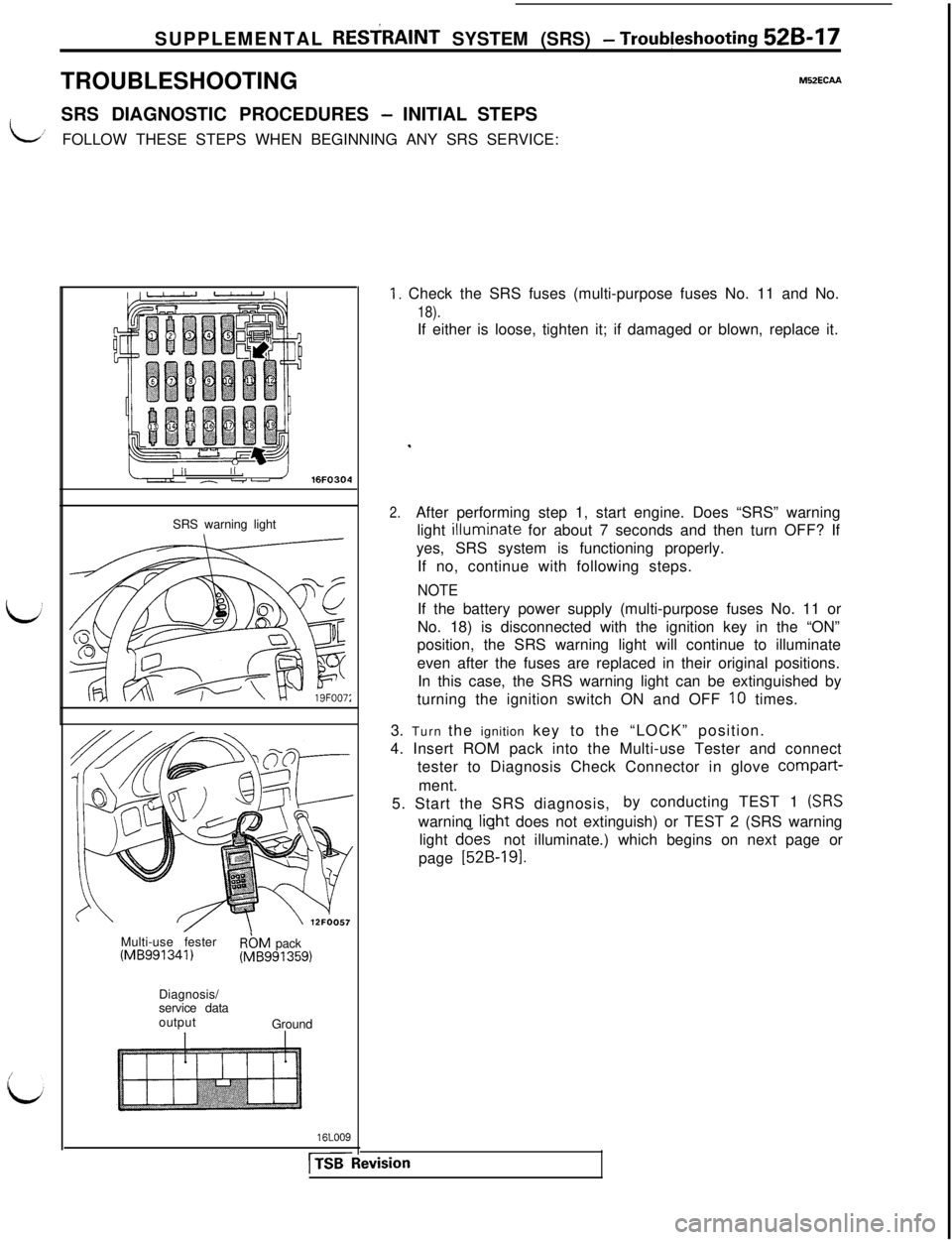
SUPPLEMENTAL RESfRAlNT SYSTEM (SRS) - Troub!eshooting 52B-17TROUBLESHOOTING
M52ECAA
idSRS DIAGNOSTIC PROCEDURES
- INITIAL STEPS’FOLLOW THESE STEPS WHEN BEGINNING ANY SRS SERVICE:
/II/ ,- -u’ 16FO304
SRS warning light
Multi-use fester
(MB991341)RbM pack(MB991359)
Diagnosis/
service data
output
Ground
16LOO9
[TSB
1. Check the SRS fuses (multi-purpose fuses No. 11 and No.
18).If either is loose, tighten it; if damaged or blown, replace it.
.
2.After performing step 1, start engine. Does “SRS” warning
light
illumi.nate for about 7 seconds and then turn OFF? If
yes, SRS system is functioning properly.
If no, continue with following steps.
NOTEIf the battery power supply (multi-purpose fuses No. 11 or
No. 18) is disconnected with the ignition key in the “ON”
position, the SRS warning light will continue to illuminate
even after the fuses are replaced in their original positions.
In this case, the SRS warning light can be extinguished by
turning the ignition switch ON and OFF
10 times.
3. Turn the ignition key to the “LOCK” position.
4. Insert ROM pack into the Multi-use Tester and connect
tester to Diagnosis Check Connector in glove compart-
ment.
5. Start the SRS diagnosis,by conducting TEST 1
(SRSwarninq liqht does not extinguish) or TEST 2 (SRS warning
light does- not illuminate.) which begins on next page or
page
[52B-191.
ivision
Page 1028 of 1146
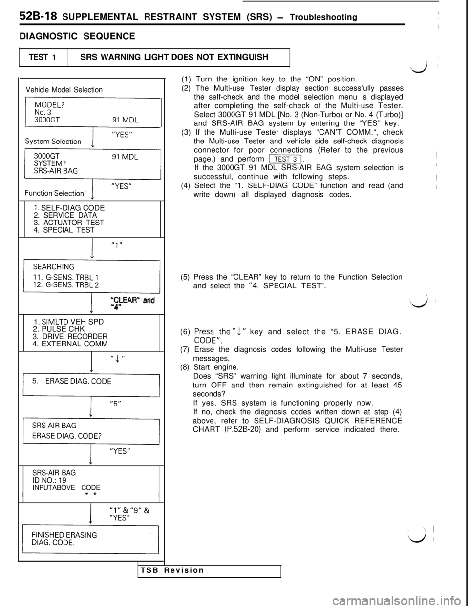
52B-18 SUPPLEMENTAL RESTRAINT SYSTEM (SRS) - Troubleshooting
DIAGNOSTIC SEQUENCE
TEST 1SRS WARNING LIGHT DOES NOT EXTINGUISH
\1 I
Vehicle Model Selection
{
F
1. SELF-DIAG CODE2. SERVICE DATA
3. ACTUATOR TEST
4. SPECIAL TEST
,, I,
0
“CLEAR” and“4”1.
SIMLTD VEH SPD
2. PULSE CHK
3. DRIVE RECORDER4. EXTERNAL COMM
” 1 ”
1’1
y,,
SRS-AIR BAGID NO.: 19INPUTABOVE CODE
I(1) Turn the ignition key to the “ON” position.
(2) The Multi-use Tester display section successfully passes
the self-check and the model selection menu is displayed
after completing the self-check of the Multi-use Tester.
Select 3000GT 91 MDL [No. 3 (Non-Turbo) or No. 4 (Turbo)]
and SRS-AIR BAG system by entering the “YES” key.
(3) If the Multi-use Tester displays “CAN’T COMM.“, check
the Multi-use Tester and vehicle side self-check diagnosis
TSB Revisionconnector for poor connections (Refer to the previous
page.) and perform
[I.If the 3000GT 91 MDL SRS-AIR BAG system selection is
successful, continue with following steps.
(4) Select the “1. SELF-DIAG CODE” function and read (and
write down) all displayed diagnosis codes.
(5) Press the “CLEAR” key to return to the Function Selection
and select the
“4. SPECIAL TEST”.
(6) Pr+FE,the ”
1 ” key and select the “5. ERASE DIAG.
(7) Erase the diagnosis codes following the Multi-use Tester
messages.
(8) Start engine.
Does “SRS” warning light illuminate for about 7 seconds,
turn OFF and then remain extinguished for at least 45
seconds?
If yes, SRS system is functioning properly now.
If no, check the diagnosis codes written down at step (4)
above, refer to SELF-DIAGNOSIS QUICK REFERENCE
CHART
(P.52B-20) and perform service indicated there.
Page 1049 of 1146
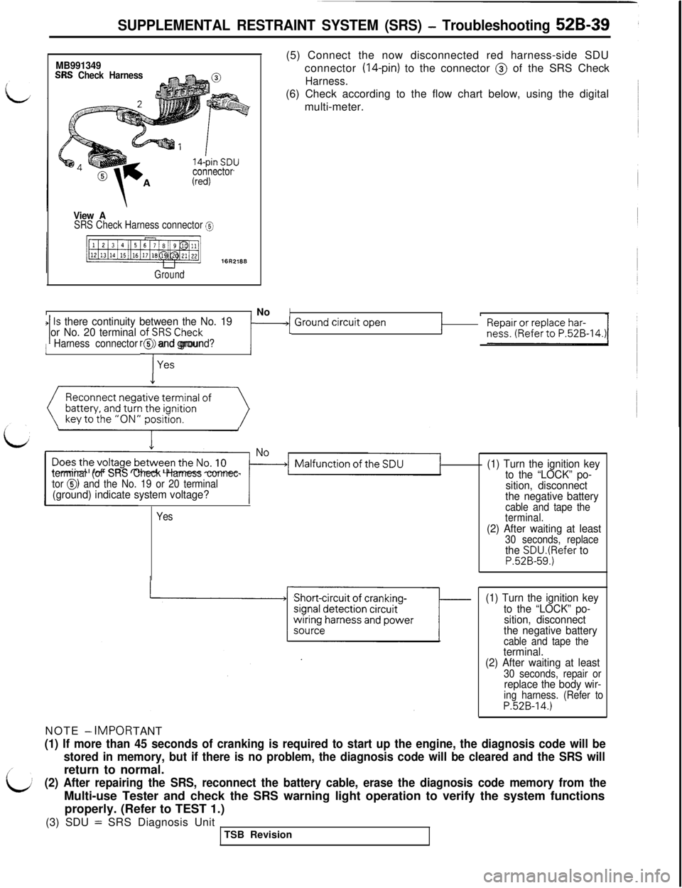
SUPPLEMENTAL RESTRAINT SYSTEM (SRS) - Troubleshooting 52B-39
MB991349SRS Check Harness
connector
View ASRS Check Harness connector @
Ground
II No(5) Connect the now disconnected red harness-side SDU
connector
(14-pin) to the connector @ of the SRS Check
Harness.(6) Check according to the flow chart below, using the digital
multi-meter.
IIIIs there continuity between the No. 191 or No. 20 terminal ofi;RSCheck‘1 ~~~~~;,0~~~~~~.~~~-14.~r1 Ground ‘jrcuit Open1Harness connector @ and ground?
Reconnect negative terminal of
(()
terminal (of SRS Check Harness connec-
tor 0) and the No. 19 or 20 terminal(ground) indicate system voltage?NOTE
- IMPOR
TANT
Yes
(1) Turn the ignition key
to the “LOCK” po-
sition, disconnect
the negative battery
cable and tape the
terminal.
(2) After waiting at least30 seconds, replacethe SDU.(Refer toP.52B-59.)
(1) Turn the ignition key
to the “LOCK” po-
sition, disconnect
the negative battery
cable and tape theterminal.
(2) After waiting at least
30 seconds, repair orreplace the body wir-ing harness. (Refer toP.52B-14.)
(1) If more than 45 seconds of cranking is required to start up the engine, the diagnosis code will be
stored in memory, but if there is no problem, the diagnosis code will be cleared and the SRS willreturn to normal.
(2) After repairing the SRS, reconnect the battery cable, erase the diagnosis code memory from theMulti-use Tester and check the SRS warning light operation to verify the system functions
properly. (Refer to TEST 1.)
(3) SDU
= SRS Diagnosis Unit
TSB Revision