oil temperature MITSUBISHI 3000GT 1991 Workshop Manual
[x] Cancel search | Manufacturer: MITSUBISHI, Model Year: 1991, Model line: 3000GT, Model: MITSUBISHI 3000GT 1991Pages: 1146, PDF Size: 76.68 MB
Page 1099 of 1146
HEATERS AND MANUAL AIR CbNDlTlONER -Service Adjustment Procedures 55 17
ADJUSTMENT PROCEDURES(1) Select a quiet area for testing. Duplicate conditions as much
as possible. Switch compressor on and off several times to
clearly identify compressor noise.
To duplicate high ambient conditions (high head pressure),
restrict air flow through condenser. Install manifold gauge
set to make sure discharge pressure doesn’t exceed 2,070
kPa (300 psi).
(2) Tighten all compressor mounting bolts, clutch mounting
bolt, and compressor drive belt. Check to assure clutch coil
is tight (no rotation or wobble).
(3) Check refrigerant hoses for rubbing or interference that can
cause unusual noises.
(4) Check refrigerant charge. (See “Charging System”.)
(5) Recheck compressor noise as in Step 1.
(6) If noise still exists, loosen compressor mounting bolts and
retorque. Repeat Step 1.
(7) If noise continues, replace compressor and repeat Step 1.
POWER RELAY CHECKMBBFNAK(1) Remove the radiator fan motor relays (HI) and (LO) from the
relay box on the right of the engine compartment.
(2) Remove the radiator fan motor relay (air conditioner),
condenser fan motor relays (HI) and (LO), and
air-conditioner compressor relay from the relay box on the left
of the engine compartment.
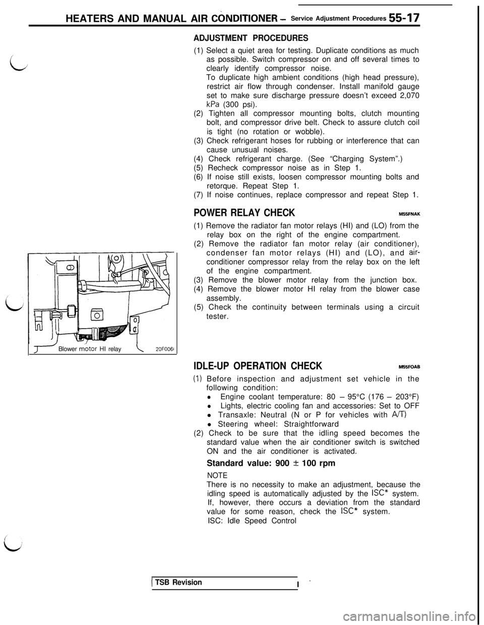
(3) Remove the blower motor relay from the junction box.
(4) Remove the blower motor HI relay from the blower case
assembly.
(5) Check the continuity between terminals using a circuit
tester.
J Blower m.otor HI relay\2OFOO6l
IDLE-UP OPERATION CHECKM55FOAB
(1) Before inspection and adjustment set vehicle in the
following condition:
lEngine coolant temperature: 80 - 95°C (176 - 203°F)
lLights, electric cooling fan and accessories: Set to OFF
l Transaxle: Neutral (N or P for vehicles with
A/T)l Steering wheel: Straightforward
(2) Check to be sure that the idling speed becomes the
standard value when the air conditioner switch is switched
ON and the air conditioner is activated.
Standard value: 900
+ 100 rpm
NOTEThere is no necessity to make an adjustment, because the
idling speed is automatically adjusted by the ISC” system.
If, however, there occurs a deviation from the standard
value for some reason, check the ISC” system.
ISC: Idle Speed Control
1 TSB RevisionI -
Page 1113 of 1146
zz
h34\
*
Engine speed rpm2OPO2S
\CrankshaftTapered part
20A0157
REVOLUTION PICK UP SENSOR CHECKMeasure the resi")
HEATERS AND MANUAL AIR CONDITIONER - Compressor55-3120N003d
2OFOO96
I
Ec-3
3180?+I! (25)zz
h34\
*
Engine speed rpm2OPO2S
\CrankshaftTapered part
20A0157
REVOLUTION PICK UP SENSOR CHECKMeasure the resistance between terminals
@ and @ of the
connector.
Normal resistance: 405 + 35 R when ambient temperatureis
20°C (68°F)
If the measurement deviates greatly from the above resis-
tance, replace the revolution pick up sensor assembly.
CONTROL VALVE CHECKThe control valve detects a low pressure level during the
operation of the air conditioner, and adjusts the amount of
refrigerant to be bypassed.
(1) Operate the air conditioner under a high temperature loadcondition (when vehicle interior temperature is high).
(2) Connect a low pressure gauge to the air compressor.
(3) Operate the air conditioner with the engine running at idle.
(4) Gradually increase the engine speed while observing the
low pressure gauge.
If the valve is normal, the low pressure drops slowly as the
engine speed increases until a pressure of 180
kPa (25 psi)
is reached, at which point the pressure temporarily ceasesto drop. Then, the pressure again starts dropping as the
engine speed further increases.If the valve is abnormal, the low pressure drops in direct
proportion to the increase in engine speed without a
temporary leveling off at the 180 kPa (25 psi) pressure level.
If the low pressure drops like this, replace the control valve.
SERVICE POINTS OF REASSEMBLYM556HAF
8. INSTALLATION OF CLUTCH COIL
Align the pin of the clutch coil with the pin hole in the fronthousing, and then fit it into the hole.
7. INSTALLATION OF SNAP RING
Install the snap ring so that the tapered surface is at the
outer side.
1 TSB Revision
Page 1121 of 1146
Pre-removal and Post-installation Operationl Draining and Refilling of Engine Coolant(Refer to GROUP 00 - Maintenance Service.)
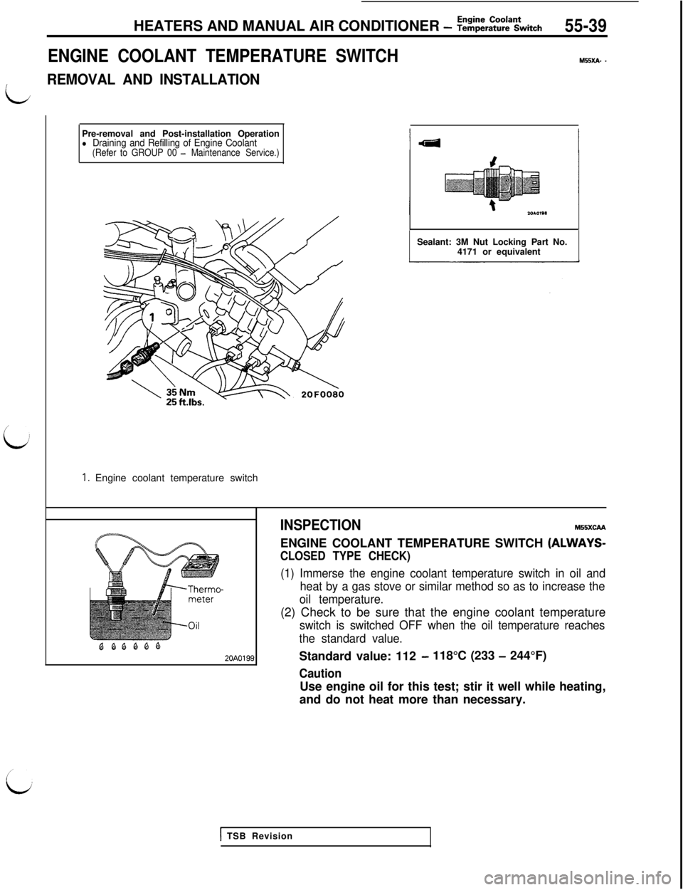
1. Engine coolant temperature switchHEATERS AND MANUAL AIR CONDITIONER
- Z!&E%Ltch55-39
ENGINE COOLANT TEMPERATURE SWITCH
M55xA- -
L
REMOVAL AND INSTALLATIONSealant: 3M Nut Locking Part No.
4171 or equivalent
BQQQQQ20A0199INSPECTION
MSSXCAAENGINE COOLANT TEMPERATURE SWITCH
(ALWAYS-
CLOSED TYPE CHECK)
(1) Immerse the engine coolant temperature switch in oil and
heat by a gas stove or similar method so as to increase the
oil temperature.(2) Check to be sure that the engine coolant temperature
switch is switched OFF when the oil temperature reaches
the standard value.Standard value: 112
- 118°C (233 - 244°F)
CautionUse engine oil for this test; stir it well while heating,
and do not heat more than necessary.
1 TSB Revision