body MITSUBISHI 3000GT 1991 Service Manual
[x] Cancel search | Manufacturer: MITSUBISHI, Model Year: 1991, Model line: 3000GT, Model: MITSUBISHI 3000GT 1991Pages: 1146, PDF Size: 76.68 MB
Page 1 of 1146
Volume lm
I ‘k,‘6III
Engine, Chassis & Bodyf
Page 4 of 1146

dir J
bag module, clock spring, interconnecting wiring. Other SRS-related comp\
onents (that may have to be
(*).
The Supplemental Restraint System (SRSI-related com")
SUPPLEMENTAL RESTRAINT SYSTEM (SRS)
dir J
bag module, clock spring, interconnecting wiring. Other SRS-related comp\
onents (that may have to be
(*).
The Supplemental Restraint System (SRSI-related components are shown in the following MASTER TABLE
OF CONTENTS. Be sure to carefully read and understand the WARNING below \
before proceeding.
Group number
22.23
32
36
42
52A
Group nameSRS-related components
FUELCRUISE CONTROL SYSTEM/ P.13-185
MANUALTRANSAXLE.TRANSAXLE CONTROLAUTOMATIC TRANSAXLE
POWER PLANT MOUNTRIGHT MEMBER, LEFT MEMBER AND CROSSMEMBERP.32-6
ELECTRONIC CONTROLSUSPENSION’STEERING ANGULAR VELOCITY SENSORP.33B-19
PARKING BRAKESPARKING BRAKE LEVER AND PARKiNG BRAKE CABLE/ P.36~5I
STEERING/POWER STEERING GEAR BOX/ P.37A-17
/STEERING WHEEL AND SHAFTj P.37A-13
BODY
INTERIOR
FENDER
FLOOR CONSOLE/ P.52A-11
FRONT SEAT
INSTRUMENT PANEL
P52A-18
P.52A-8
CHASSIS ELECTRICAL
SEAT BELT
COLUMN SWITCH
HORN SWITCH
IGNITION SWITCH
P.52A-25
P.54-73
P.54-78
1 P.54-6
RADIO REMOTE-CONTROL/ P.54.110
HEATER, AIR CONDITIONERAIR-CONDITIONER CONTROL PANELAND VENTILATIONAIR-CONDITIONER CONTROL UNITP.55-56
/DAMPER CONTROL MOTOR ASSEMBLYI
/HEATER CONTROL ASSEMBLY1 P.55-18I
HEATER UNIT.1 P.55-22
WARNING!
VENTILATORS (INSTRUMENT PANEL)P.55-36
(1) Improper service or maintenance of any component of the SRS, or an\
y SRSrelated component,
can lead to personal injury or death to service personnel (from inadver\
tent firing of the air bag) or
to the driver (from rendering the SRS inoperative).
(260°F) in baking or in
drying after painting, remove the SRS components (air bag module, SRS d\
iagnosis unit, front
perfarmed
only at an authorized MITSUBISHI dealer.
52B
- Supplemental Restraint System (SRS), before beginning any service or m\
aintenance of any
component of the SRS or any SRS-related component.
1 TSB RevisionI
Page 14 of 1146
00-10GENERAL - Vehicle Identification
0060046
.:@I*
@+!jg.., ,”
0
<1
~~~ k
,.‘.r, SS?b‘,,.‘$ .’‘S,‘,,:’
t
I
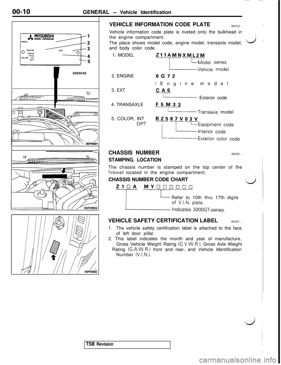
nf/OOFDO&VEHICLE INFORMATION CODE PLATE
MOOCD- .IVehicle information code plate is riveted onto the bulkhead in
the engine compartment.
:
i3' 'The place shows model code, engine model, transaxle model,
and body color code.
1. MODEL
ZllAMNXMLZM
L2iie ‘zze[2. ENGINE
6672/Engine model
3. EXTCA6
Y Exterior code
4. TRANSAXLE
F5M33
-Transaxle model
5. COLOR, INT
R2587VQ3V
OPT-p=~izgTj+Ly~deCHASSIS NUMBER
MOOCE- -
STAMPING. LOCATIONThe chassis number is stamped on the top center of thefirewall located in the engine compartment.
CHASSIS NUMBER CODE CHART
ZlOA MY[7000~10
Y cd:at!s t:beOGT-series. Refer to 10th thru 17th digits
VEHICLE SAFETY CERTIFICATION LABEL
MOOCF- -
1.The vehicle safety certification label is attached to the face
of left door pillar.
2. This label indicates the month and year of manufacture,
Gross Vehicle Weight Rating
(G.V.W.R.), Gross Axle Weight
Rating
(G.A.W.R.) front and rear, and Vehicle Identification
Number
(V.I.N.).
TSB Revision
Page 15 of 1146

GENERAL - Vehicle Identification00-I 1
c
Theft protection label
For original parts
OOK619
For replacement parts
[i]
001621ENGINE MODEL STAMPING
MOOCG- .
I, The engine model number is stamped at the front side on
the top edge of the cylinder block as shown in the
following:
Engine modelEngine displacement
6672
3.0 liters (181.4 cu.in.12. The engine serial number is stamped near the engine
model number, and the serial number cycles, as shown
below
Engine serial number
AA0201 to YY9999Number cyclingAA0201--- - -+ AA9999
L ABOOOI-- - - ---f AY9999
L BAOOOI - - - - + YY9999
THEFT PROTECTION.MOOCIACIn order to protect against theft, a Vehicle Identification
Number
(VIN) is stamped in, or attached as a label to, the
following major parts of the engine and transaxle, as well as
main outer panels:
Engine cylinder block, Transaxle housing, Fender, Door, Quar-
ter panel, Hood, Liftgate, Bumpers
In addition, a theft-protection label is attached
to‘ replacement
parts for the body outer panel main components, and the same
data are stamped into replacement parts for the engine and the
transaxle.
Cautions regarding panel repairs
1. When repainting original parts, do so after first mask-
ing the theft-protection label, and, after painting, be
sure to peel off the masking tape.
2. The theft-protection label for replacement parts is
covered by masking tape, so such parts can be paintedas is. The masking tape should be removed after
painting is finished.
3.The theft-protection label should not be removed fromoriginal parts or replacement parts.
c
1 TSB Revision
Page 22 of 1146
00-18
GENERAL - Towing and Hoisting
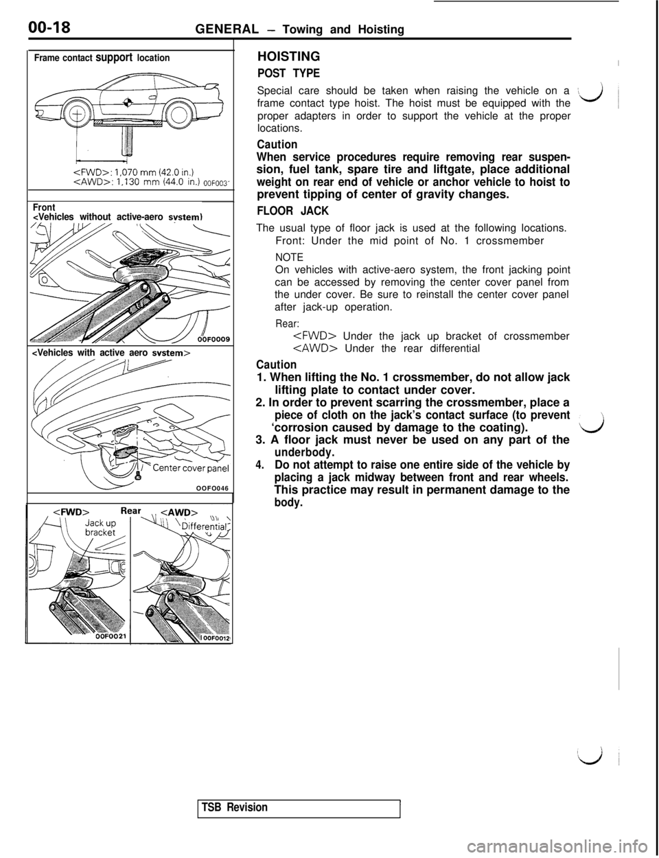
Frame contact support location
1,070 mm (42.0 in.)
Front
POST TYPESpecial care should be taken when raising the vehicle on a
\frame contact type hoist. The hoist must be equipped with theL)proper adapters in order to support the vehicle at the proper
locations.
Caution
When service procedures require removing rear suspen-sion, fuel tank, spare tire and liftgate, place additional
weight on rear end of vehicle or anchor vehicle to hoist toprevent tipping of center of gravity changes.
FLOOR JACKThe usual type of floor jack is used at the following locations.
Front: Under the mid point of No. 1 crossmember
NOTEOn vehicles with active-aero system, the front jacking point
can be accessed by removing the center cover panel from
the under cover. Be sure to reinstall the center cover panel
after jack-up operation.
Rear:
Caution1. When lifting the No. 1 crossmember, do not allow jack
lifting plate to contact under cover.
2. In order to prevent scarring the crossmember, place a
piece of cloth on the jack’s contact surface (to prevent‘corrosion caused by damage to the coating).
d3. A floor jack must never be used on any part of the
underbody.
4.Do not attempt to raise one entire side of the vehicle by
placing a jack midway between front and rear wheels.This practice may result in permanent damage to the
body.
TSB Revision
Page 23 of 1146
GENERAL - Towing and Hoisting
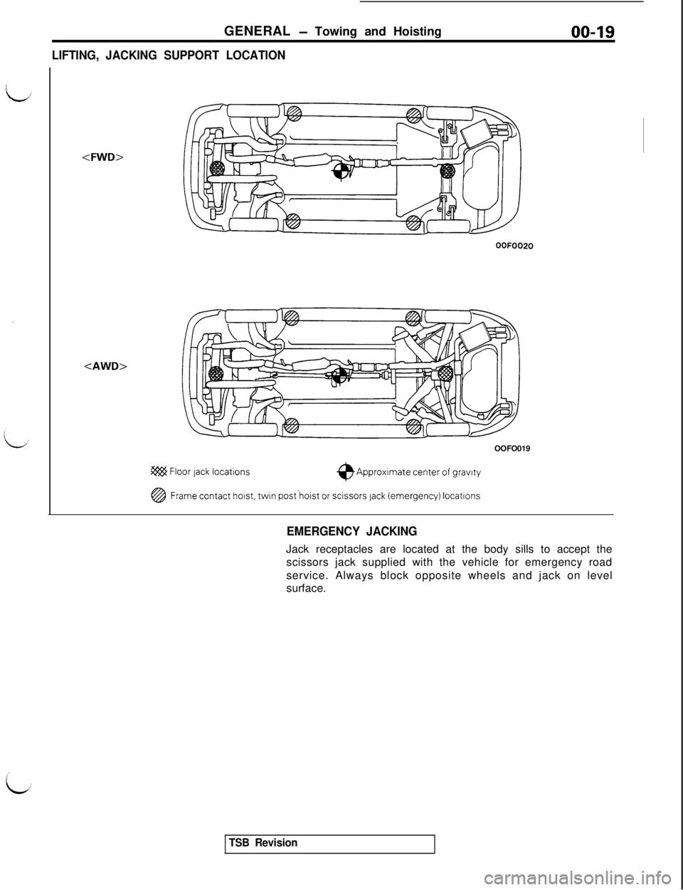
LIFTING, JACKING SUPPORT LOCATION00-19
OOFOO20OOFO019
@ Floor lack locations$Approximate center of gravrty
@Frame contact hoist. twin post‘hoist or scissors lack (emergency) locatlons
EMERGENCY JACKINGJack receptacles are located at the body sills to accept the
scissors jack supplied with the vehicle for emergency road
service. Always block opposite wheels and jack on level
surface.
TSB Revision
Page 28 of 1146
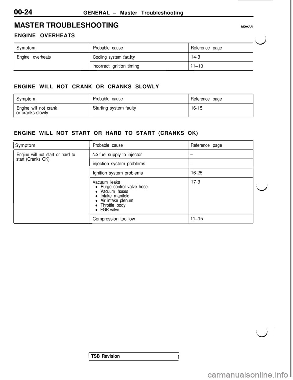
00-24GENERAL - Master Troubleshooting
MASTER TROUBLESHOOTING
MOOWWENGINE OVERHEATS
Symptom
Engine overheatsProbable cause
Cooling system
faulty
, incorrect ignition timing
Reference page
14-3
11-13
v’.ENGINE WILL NOT CRANK OR CRANKS SLOWLY
Symptom
Engine will not crankor cranks slowly
Probable cause
Starting system faulty
Reference page
16-15ENGINE WILL NOT START OR HARD TO START (CRANKS OK)
1 Symptom
Engine will not start or hard to
start (Cranks OK)Probable causeNo fuel supply to injector
injection system problems
Ignition system problems
Vacuum leaksl Purge control valve hosel Vacuum hosesl Intake manifoldl Air intake plenuml Throttle bodyl EGR valve
Reference page
-
-
16-25
17-3
Compression too low
11-15
d
1 TSB Revision1
Page 29 of 1146
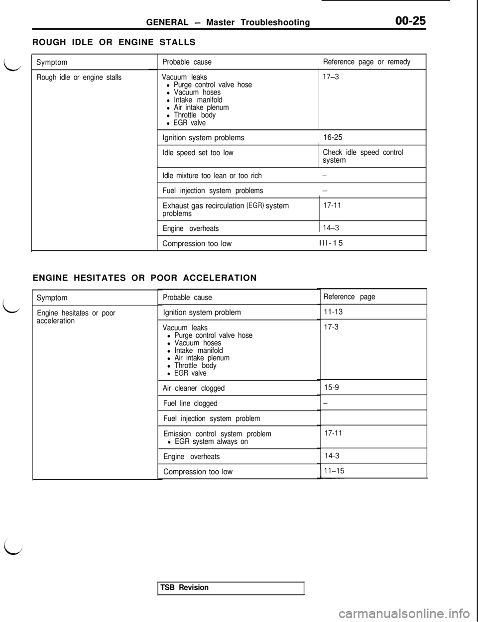
GENERAL - Master Troubleshooting
ROUGH IDLE OR ENGINE STALLS
LProbable causeReference page or remedy
Symptom
Rough idle or engine stallsVacuum leaks
l Purge control valve hosel Vacuum hosesl Intake manifoldl Air intake plenuml Throttle bodyl EGR valve
Ignition system problems16-25
Idle speed set too lowCheck idle speed controlsystem
Idle mixture too lean or too rich-
Fuel injection system problems-
Exhaust gas recirculation (EGR) systemproblems17-11
Engine overheats
114-3
Compression too lowIll-15
ENGINE HESITATES OR POOR ACCELERATION
L
Reference pageSymptomProbable cause
Ignition system problem
Vacuum leaksl Purge control valve hosel Vacuum hosesl Intake manifoldl Air intake plenuml Throttle bodyl EGR valve
Air cleaner clogged
Fuel line clogged
Fuel injection system problem
Emission control system problem
l EGR system always on
Engine overheats
Compression too low11-13
Engine hesitates or poor
acceleration
17-3
15-9
-
17-11
14-3
TSB Revision
Page 48 of 1146
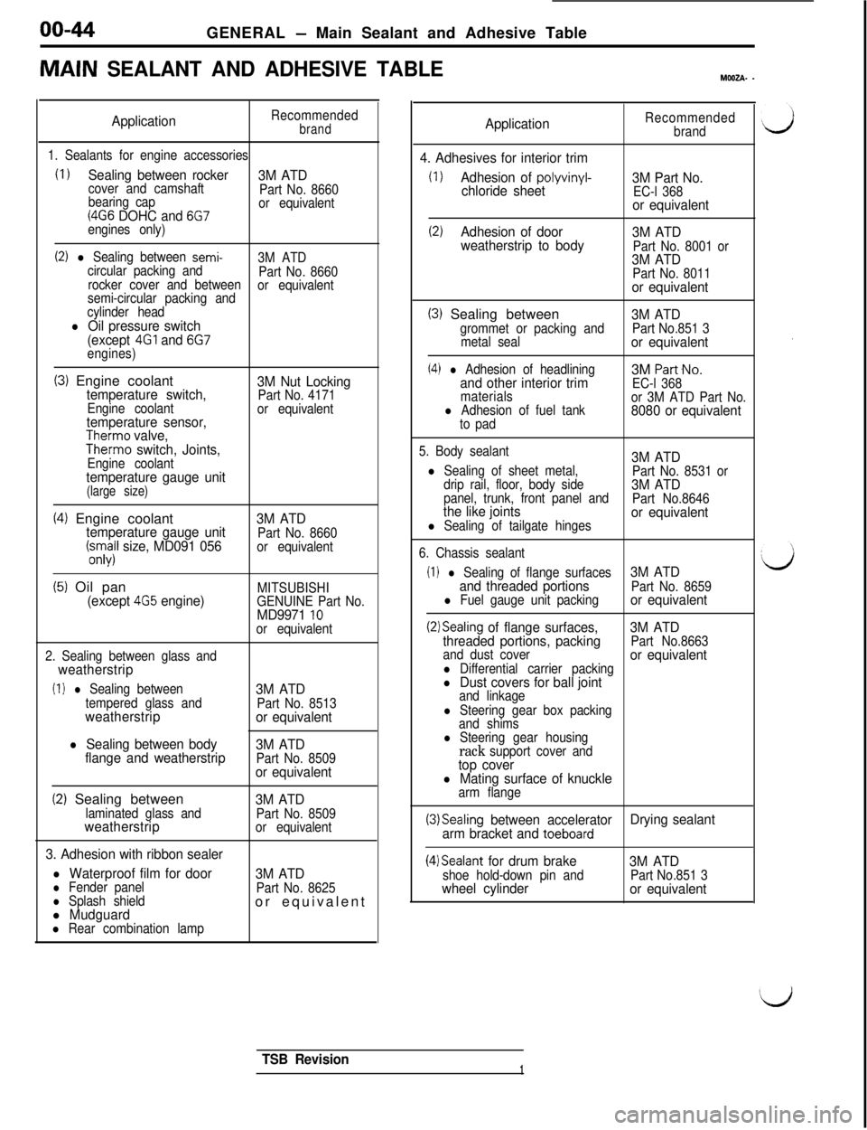
00-44
GENERAL - Main Sealant and Adhesive Table
MAIN SEALANT AND ADHESIVE TABLEMWZA- -
ApplicationRecommendedbrand
1. Sealants for engine accessories
(I 1Sealing between rocker
3M ATDcover and camshaft
Part No. 8660
bearing cap
(4G6 DOHC and 6G7or equivalent
engines only)
(2) l Sealing between semi-3M ATD
circular packing and
Part No. 8660
rocker cover and between
semi-circular packing andor equivalent
cylinder head
l Oil pressure switch
(except 4Gl and 6G7engines)
(3) Engine coolanttemperature switch,Engine coolanttemperature sensor,Therm0 valve,Therm0 switch, Joints,Engine coolanttemperature gauge unit(large size)
3M Nut LockingPart No. 4171
or equivalent
(4) Engine coolanttemperature gauge unit(;.s;il size, MD091 0563M ATDPart No. 8660
or equivalent
(5) Oil pan(except 4G5 engine)MITSUBISHI
GENUINE Part No.
MD9971 10or equivalent
2. Sealing between glass and
weatherstrip
(I 1 l Sealing between
tempered glass and
weatherstrip
l Sealing between body
flange and weatherstrip3M ATD
Part No. 8513or equivalent
3M ATD
Part No. 8509or equivalent
(2) Sealing betweenlaminated glass andweatherstrip
3. Adhesion with ribbon sealer
l Waterproof film for doorl Fender panell Splash shieldl Mudguardl Rear combination lamp
3M ATDPart No. 8509
or equivalent
3M ATDPart No. 8625or equivalent
ApplicationRecommended
brand
4. Adhesives for interior trim
(1)Adhesion of polyvinyl-chloride sheet3M Part No.EC-l 368or equivalent
(2)Adhesion of door
3M ATD
weatherstrip to body
Part No. 8001 or3M ATDPart No. 8011or equivalent
(3) Sealing betweengrommet or packing and
metal seal
(4) l Adhesion of headliningand other interior trimmaterialsl Adhesion of fuel tank
to pad
3M ATDPart No.851 3or equivalent3M
Part-No.
EC-l 368
or 3M ATD Part No.
8080 or equivalent
5. Body sealant3M ATDl Sealing of sheet metal,
Part No. 8531 or
drip rail, floor, body side3M ATDpanel, trunk, front panel and
Part No.8646the like jointsl Sealing of tailgate hingesor equivalent
6. Chassis sealant
(I 1 l Sealing of flange surfaces3M ATD
and threaded portions
Part No. 8659l Fuel gauge unit packingor equivalent
(2)Sealing of flange surfaces,3M ATD
threaded portions, packingPart No.8663
and dust cover
l Differential carrier packingor equivalent
l Dust covers for ball jointand linkage
l Steering gear box packing
and shims
l Steering gear housingrack support cover andtop coverl Mating surface of knucklearm flange
(3)Sealing between accelerator
arm bracket and toeboardDrying sealant
(4)Sealant for drum brakeshoe hold-down pin andwheel cylinder3M ATDPart No.851 3or equivalent
TSB Revision1
Page 57 of 1146
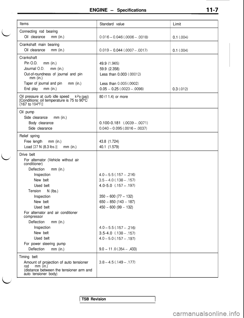
ENGINE - Specifications
/
L
L/
Items
Connecting rod bearing
Oil clearancemm (in.)
Crankshaft main bearing
Oil clearancemm (in.)
Crankshaft
Pin O.D.
mm (in.)
Journal O.D.mm (in.)
Out-of-roundness of journal and pin
mm (in.)
Taper of journal and pin
mm (in.)
End playmm (in.)
Oil pressure at curb idle speed
kPa (psi)
[Conditions: oil temperature is 75 to 90°C
(167 to
194”F)l
Standard value
0.016- 0.046 (.0006- .0018)
0.019 - 0.044 (.0007 - .0017)
49.9 (I ,965)
59.9 (2.358)
Less than 0.003 (.00012)
Less than 0.005 (0002)
0.05 - 0.25 (0020 - .0098)
80 (I 1.4) or more
Limit
0.1
(.004)
0.1 (.004)
0.3 (.012)
Oil pump
Side clearancemm (in.)
Body clearance0.100-0.181 (.0039-.0071)
Side clearance0.040 - 0.095 (.0016 - .0037)
Relief spring
Free lengthmm (in.)43.8 (1.724)
Load
137 N (8.3 Ibs.)]mm (in.)40.1 (1.579)
Drive belt
For alternator (Vehicle without air
conditioner)
Deflectionmm (in.)
Inspection
4.0-5.5(.157-,216)
New belt3.5-4.0(.138-,157)
Used belt4.0-5.0 (.157- ,197)
TensionN (Ibs.)
Inspection350 - 600 (77 - 132)
New belt650
- 850 (143 - 187)
Used belt450
- 600 (99 - 132)
For alternator and air conditioner
compressor
Deflectionmm (in.)
Inspection
4.0-5.5(.157-,216)
New belt3.5-4.0 (1388.157)
Used belt4.0-5.0(.157-,197)
For power steering pump
Deflection
mm (in.)9.0
- 11 .o (354 - ,433)
Timing belt
Amount of projection of auto tensioner3.8-4.5(.149-,177)rodmm (in.)(distance between the tensioner arm andauto tensioner body)
1 TSB Revision