glove box MITSUBISHI 3000GT 1991 Service Manual
[x] Cancel search | Manufacturer: MITSUBISHI, Model Year: 1991, Model line: 3000GT, Model: MITSUBISHI 3000GT 1991Pages: 1146, PDF Size: 76.68 MB
Page 987 of 1146
INTERIOR - Instrument Panel52A-9
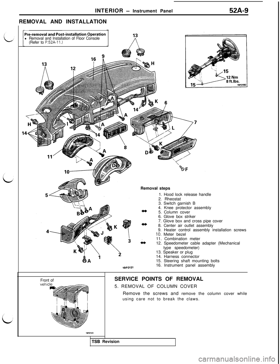
REMOVAL AND INSTALLATION
Pre-removal and Post-installation Operationl Removal and Installation of Floor Console
(Refer to P.52A-11.)
19FO131Removal steps
1. Hood lock release handle
2. Rheostat
3. Switch garnish B
4. Knee protector assembly
5. Column cover
6. Glove box striker
7. Glove box and cross pipe cover
8. Center air outlet assembly
9. Heater control assembly installation screws
10. Meter bezel
i*11. Combination meter
12. Speedometer cable adapter (Mechanical
type speedometer)
13. Speaker or plug
14. Harness connector
15. Steering shaft mounting bolts
16. Instrument panel assembly
Front ofSERVICE POINTS OF REMOVAL
5. REMOVAL OF COLUMN COVER
Remove the screws and remove the column cover while
using care not to break the claws.TSB Revision
Page 988 of 1146
52A-10
INTERIOR - Instrument Panel
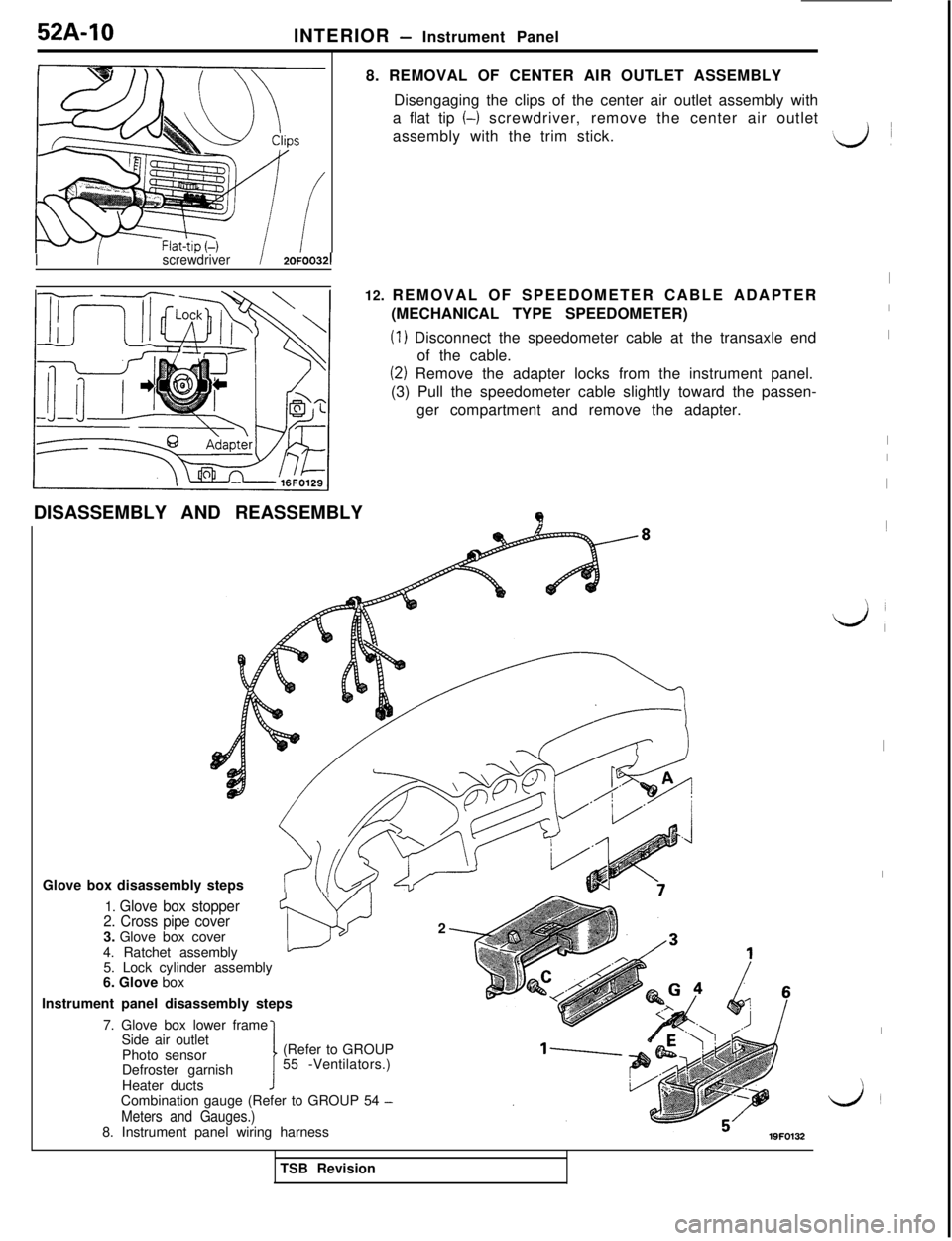
8. REMOVAL OF CENTER AIR OUTLET ASSEMBLY
Disengaging the clips of the center air outlet assembly with
a flat tip
(-1 screwdriver, remove the center air outlet
assembly with the trim stick.
IIscrewdriver/ 2OFOO321
12. REMOVAL OF SPEEDOMETER CABLE ADAPTER
(MECHANICAL TYPE SPEEDOMETER)
(1) Disconnect the speedometer cable at the transaxle end
of the cable.
(2) Remove the adapter locks from the instrument panel.
(3) Pull the speedometer cable slightly toward the passen-
ger compartment and remove the adapter.
DISASSEMBLY AND REASSEMBLY
QGlove box disassembly steps
1. Glove box stopper
2. Cross pipe cover3. Glove box cover
- w2
4. Ratchet assembly
5. Lock cylinder assembly
6. Glove box
Instrument panel disassembly steps
7. Glove box lower frame
Side air outlet
Photo sensor
Defroster garnish
Heater ducts1(Refer to GROUP
55 -Ventilators.)
Combination gauge (Refer to GROUP 54
-
Meters and Gauges.)8. Instrument panel wiring harness
19FO132
I
I
I
I
I
I1
d’
I
I
I
L&iTSB Revision
Page 1100 of 1146
55-I 8HEATERS AND MANUAL AIR CONDlTlONER - Heater Control Assembly
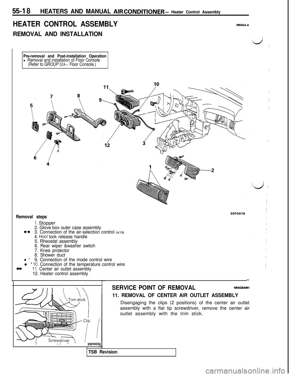
HEATER CONTROL ASSEMBLY
REMOVAL AND INSTALLATIONM55GA-A
Pre-removal and Post-installation Operationl Removal and installation of Floor Console
(Refer to GROUP 52A- Floor Console.)
Removal steps
1. Stopper2. Glove box outer case assembly**3. Connection of the air-selection control wire
4. Ho01 lock release handle
5. Rheostat assembly
6. Rear wiper &washer switch
7. Knee protector
8. Shower duct
l *9. Connection of the mode control wirel * 10. Connection of the temperature control wirea*11. Center air outlet assembly
12. Heater control assembly
2OFOO78
III’ ’2OFOO3
ii,
I
I
I
I
I
‘d i
-
SERVICE POINT OF REMOVALM55GBAMl
11. REMOVAL OF CENTER AIR OUTLET ASSEMBLYDisengaging the clips (2 positions) of the center air outlet
assembly with a flat tip screwdriver, remove the center air
outlet assembly with the trim stick.
TSB Revision
Page 1105 of 1146
HEATERS AND MANUAL AIR CONDITIONER - Blower Assembly55-23
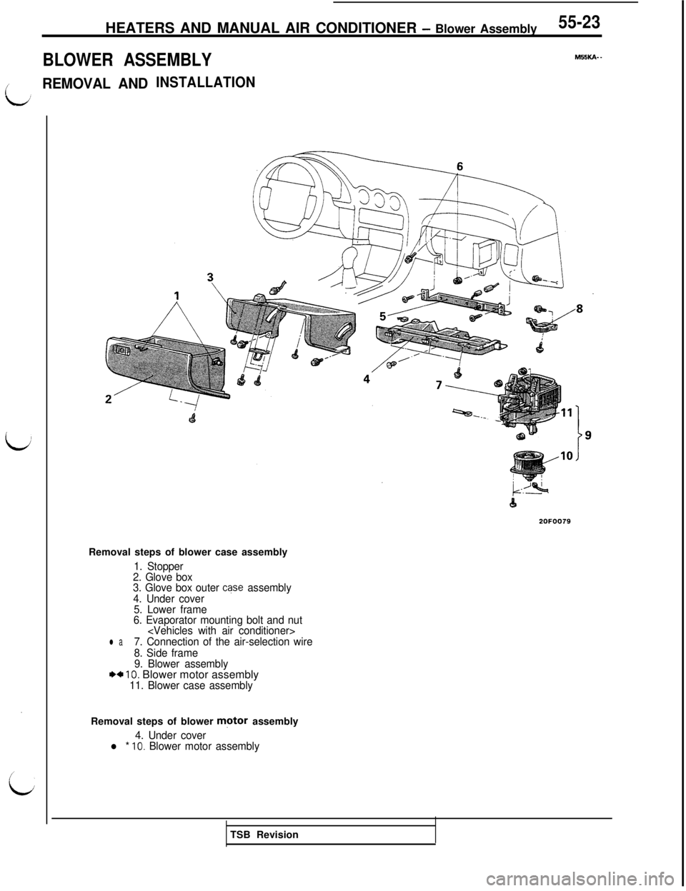
BLOWER ASSEMBLY
M55KA- _
/REMOVAL ANDINSTALLATION2OFOO79
Removal steps of blower case assembly
1. Stopper
2. Glove box
3. Glove box outer
case assembly
4. Under cover
5. Lower frame
6. Evaporator mounting bolt and nut
l a7. Connection of the air-selection wire
8. Side frame
9. Blower assembly
*+ 10. Blower motor assembly11. Blower case assemblyRemoval steps of blower
motor assembly
4. Under coverl * 10. Blower motor assemblyTSB Revision
Page 1107 of 1146
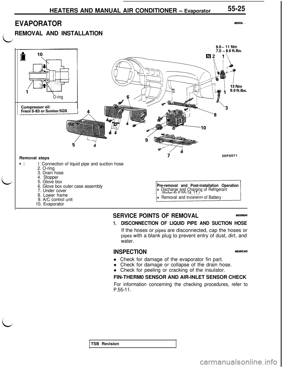
HEATERS AND MANUAL AIR CONDITIONER - Evaporator55-25
EVAPORATOR
M55RA- -
/REMOVAL AND INSTALLATION
9.0- 11 Nm
7.0 - 8.0 ftlbs.
i
O-ringRemoval steps
l *I, Connection of liquid pipe and suction hose
2. O-ring
3. Drain hose
4. Stopper
5. Glove box
6. Glove box outer case assembly
7. Under cover
8. Lower frame
9. A/C control unit
10. Evaporator
Pre-removal and Post-installation Operationl Discharge and Charging of Refrigerant
l Removal and lns~allation of Battery
SERVICE POINTS OF REMOVALM55RBAl
1.DISCONNECTION OF LIQUID PIPE AND SUCTION HOSEIf the hoses or pipes are disconnected, cap the hoses or
pipes with a blank plug to prevent entry of dust, dirt, and
water.
INSPECTIONM55RcADl Check for damage of the evaporator fin part.
l Check for damage or collapse of the drain hose.
l Check for peeling or cracking of the insulator.
FIN-THERM0 SENSOR AND AIR-INLET SENSOR CHECK
For information concerning the checking procedures, refer to
P.55-11.
iTSB Revision
Page 1139 of 1146
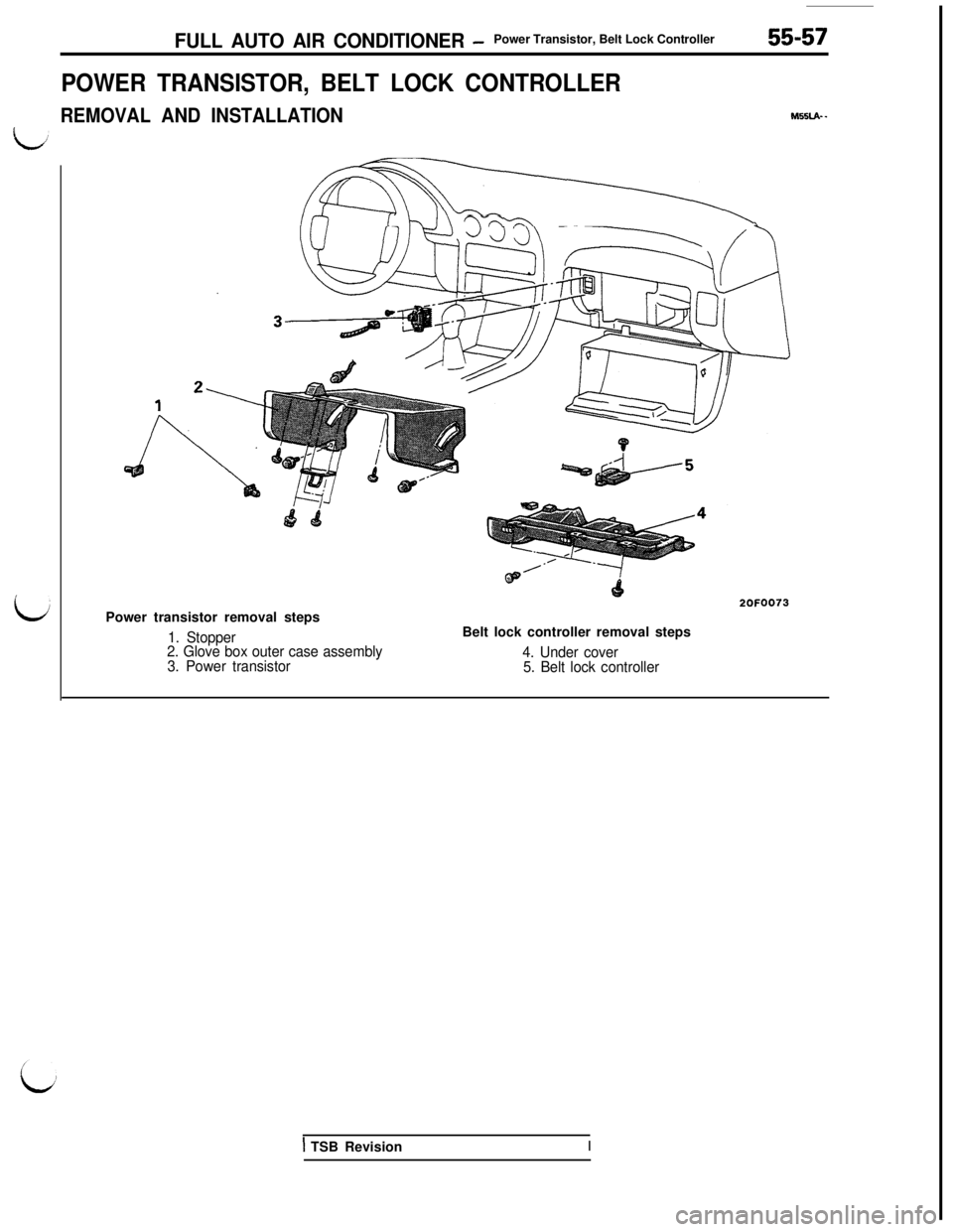
FULL AUTO AIR CONDITIONER -Power Transistor, Belt Lock Controller55-57
POWER TRANSISTOR, BELT LOCK CONTROLLER
REMOVAL AND INSTALLATION
J?nPower transistor removal steps
1. Stopper
2. Glove box outer case assembly
3. Power transistor
2OFOO73Belt lock controller removal steps
M55LA- -
4. Under cover
5. Belt lock controller
1 TSB RevisionI
Page 1140 of 1146
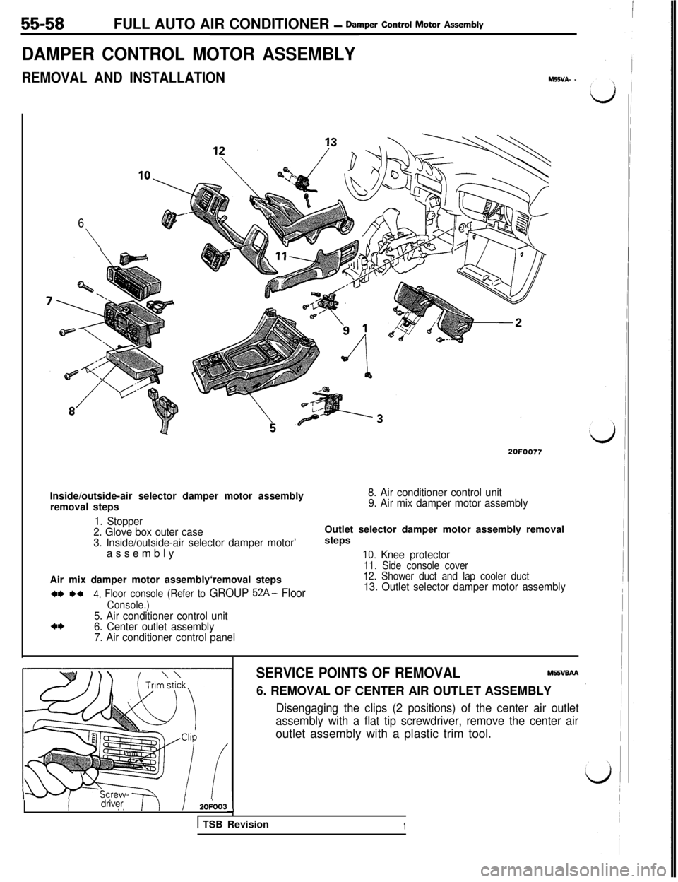
55-58FULL AUTO AIR CONDITIONER - Damper Control Motor As=W
DAMPER CONTROL MOTOR ASSEMBLY
REMOVAL AND INSTALLATIONM55VA- -
6
\
2OFOO77Inside/outside-air selector damper motor assembly
removal steps
8. Air conditioner control unit
9. Air mix damper motor assembly
1. Stopper
2. Glove box outer case
3. Inside/outside-air selector damper motor’assemblyOutlet selector damper motor assembly removal
steps
IO. Knee protector11. Side console coverAir mix damper motor assembly‘removal steps
w *a4. Floor console (Refer to GROUP 52A- Floor
Console.)5. Air conditioner control unita*6. Center outlet assembly
7. Air conditioner control panel
12. Shower duct and lap cooler duct13. Outlet selector damper motor assembly
IIdriver, ,/ 20;003--t
1 TSB Revision
SERVICE POINTS OF REMOVALM55vaAA6. REMOVAL OF CENTER AIR OUTLET ASSEMBLY
Disengaging the clips (2 positions) of the center air outlet
assembly with a flat tip screwdriver, remove the center airoutlet assembly with a plastic trim tool.
1
Page 1142 of 1146
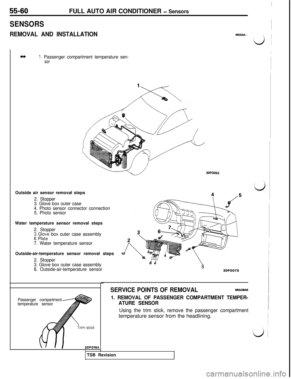
55-60
SENSORSFULL AUTO AIR CONDITIONER
- Sensors
REMOVAL AND INSTALLATIONM550A- _
4*1. Passenger compartment temperature sen-sor2OFOO63
Outside air sensor removal steps
2. Stopper
3. Glove box outer case
4. Photo sensor connector connection
5. Photo sensorWater temperature sensor removal steps
2. StopperI3: F/it; box outer case assembly
7. Water temperature sensorOutside-air-temperature sensor removal steps
2. Stopper
3. Glove box outer case assembly
8. Outside-air-temperature sensor
82OFOO75
-
Passenger compartment
temperature sensor
SERVICE POINTS OF REMOVALM5506AE
1. REMOVAL OF PASSENGER COMPARTMENT TEMPER-
ATURE SENSOR
2OPO164LlTSB Revision
Using the trim stick, remove the passenger compartmenttemperature sensor from the headlining.
I~’
I
d
I
d