jump start MITSUBISHI 3000GT 1991 Service Manual
[x] Cancel search | Manufacturer: MITSUBISHI, Model Year: 1991, Model line: 3000GT, Model: MITSUBISHI 3000GT 1991Pages: 1146, PDF Size: 76.68 MB
Page 63 of 1146
ENGINE - Service Adiustment ProceduresII-13
I_ ianltion tlminaI!H Connector for Igdpstment 6rown)
4tll II -7FUO9371IGNITION TIMING ADJUSTMENTMllFLAF
(1) The vehicle should be prepared as follows before the
inspection and adjustment.
lEngine coolant temperature: 80 - 95°C (176 - 205°F)
l Lights, electric cooling fan and accessories: OFF
l Transaxle: neutral
(P for A/T)l Steering wheel: neutral position
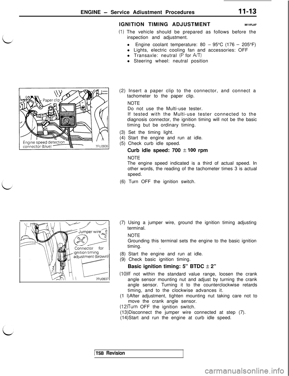
(2) Insert a paper clip to the connector, and connect a
tachometer to the paper clip.
NOTEDo not use the Multi-use tester.
If tested with the Multi-use tester connected to the
diagnosis connector, the ignition timing will not be the basic
timing but be ordinary timing.
(3) Set the timing light.
(4) Start the engine and run at idle.
(5) Check curb idle speed.
Curb idle speed: 700
f 100 rpm
NOTEThe engine speed indicated is a third of actual speed. In
other words, the reading of the tachometer times 3 is actual
speed.
(6) Turn OFF the ignition switch.
(7) Using a jumper wire, ground the ignition timing adjusting
terminal.
NOTEGrounding this terminal sets the engine to the basic ignition
timing.
\(8) Start the engine and run at idle.
(9) Check basic ignition timing.
Basic ignition timing: 5” BTDC
k 2”
(10)lf not within the standard value range, loosen the crank
angle sensor mounting nut and adjust by turning the crank
angle sensor. Turning it to the counterclockwise retards
timing, and to the clockwise advances it.
(1 l)After adjustment, tighten mounting nut taking care not to
move the crank angle sensor.
(12)Turn OFF the ignition switch.
(13)Disconnect the jumper wire connected at step (7).
(14)Start and run the engine at curb idle speed.
1 TSB Revision
Page 64 of 1146
11-14ENGINE - Service Adjustment Procedures
(15)Check to be sure that the idling ignition timing is the correct
timing.
Actual ignition timing: Approx. 15” BTDC
NOTE:d
(1) Ignition timing is variable even under normal operation.
(2) And it is automatically advanced at higher altitudes.
CURB IDLE SPEED INSPECTIONMllFMAB
(1) The vehicle should be prepared as follows before the
inspection.
lEngine coolant temperature: 80 - 95°C (176 - 205°F)
l Lights, electric cooling fan and accessories: OFF
l Transaxle: neutral
(P for A/T)l Steering wheel: neutral position
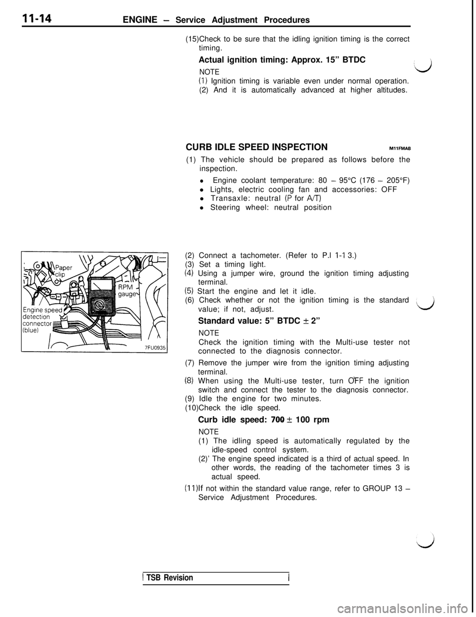
(2) Connect a tachometer. (Refer to P.l l-1 3.)
(3) Set a timing light.
(4) Using a jumper wire, ground the ignition timing adjusting
terminal.
(5) Start the engine and let it idle.
(6) Check whether or not the ignition timing is the standard
value; if not, adjust.
Standard value: 5” BTDC + 2”
NOTECheck the ignition timing with the Multi-use tester not
connected to the diagnosis connector.
(7) Remove the jumper wire from the ignition timing adjusting
terminal.
(8) When using the Multi-use tester, turn OFF the ignition
switch and connect the tester to the diagnosis connector.
(9) Idle the engine for two minutes.
(10)Check the idle speed.
Curb idle speed:
700 + 100 rpm
NOTE(1) The idling speed is automatically regulated by the
idle-speed control system.
(2)’ The engine speed indicated is a third of actual speed. In
other words, the reading of the tachometer times 3 is
actual speed.
(1l)lf not within the standard value range, refer to GROUP 13 -Service Adjustment Procedures.
d
1 TSB RevisionI
Page 138 of 1146
13-32FUEL SYSTEM - Service Adjustment Procedures
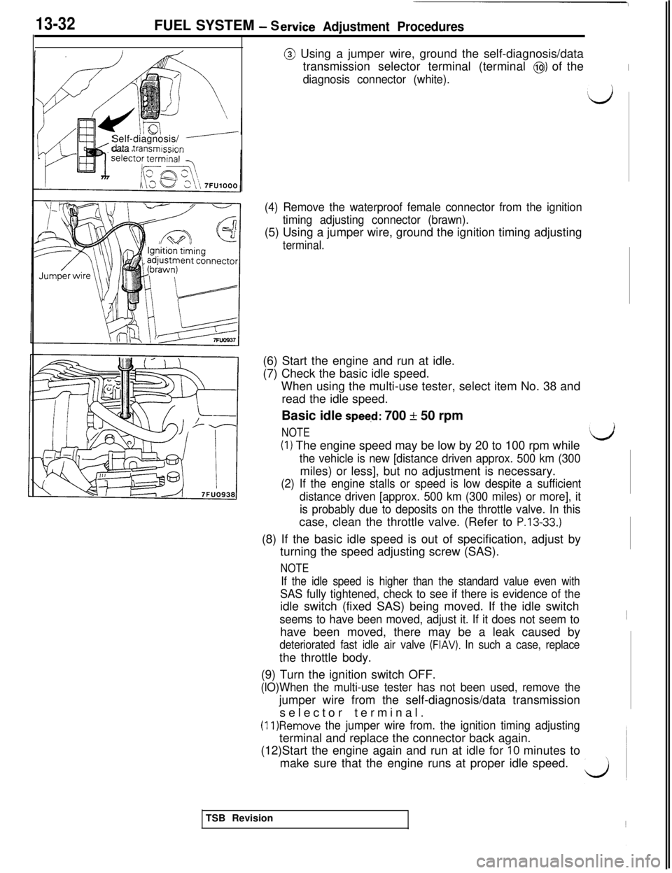
@ Using a jumper wire, ground the self-diagnosis/data
transmission selector terminal (terminal
@) of theI
diagnosis connector (white).
dSelf-diagnosis/
ydata transmission
(4) Remove the waterproof female connector from the ignition
timing adjusting connector (brawn).(5) Using a jumper wire, ground the ignition timing adjusting
terminal.(6) Start the engine and run at idle.
(7) Check the basic idle speed.
When using the multi-use tester, select item No. 38 and
read the idle speed.
Basic idle
speeci: 700 + 50 rpm
NOTE(I) The engine speed may be low by 20 to 100 rpm while
the vehicle is new [distance driven approx. 500 km (300miles) or less], but no adjustment is necessary.
(2) If the engine stalls or speed is low despite a sufficient
distance driven [approx. 500 km (300 miles) or more], it
is probably due to deposits on the throttle valve. In thiscase, clean the throttle valve. (Refer to
P.13-33.)(8) If the basic idle speed is out of specification, adjust by
turning the speed adjusting screw (SAS).
NOTE
If the idle speed is higher than the standard value even with
SAS fully tightened, check to see if there is evidence of theidle switch (fixed SAS) being moved. If the idle switch
seems to have been moved, adjust it. If it does not seem tohave been moved, there may be a leak caused by
deteriorated fast idle air valve (FIAV). In such a case, replacethe throttle body.
(9) Turn the ignition switch OFF.
(lO)When the multi-use tester has not been used, remove thejumper wire from the self-diagnosis/data transmission
selector terminal.
(11)Remove the jumper wire from. the ignition timing adjustingterminal and replace the connector back again.
(12)Start the engine again and run at idle for
10 minutes to
make sure that the engine runs at proper idle speed.
‘dTSB Revision
Page 139 of 1146
FUEL SYSTEM - Service Adjustment Procedures13-33THROTTLE BODY
(THROTrLE VALVE AREA)
CLEANINGM13FICS
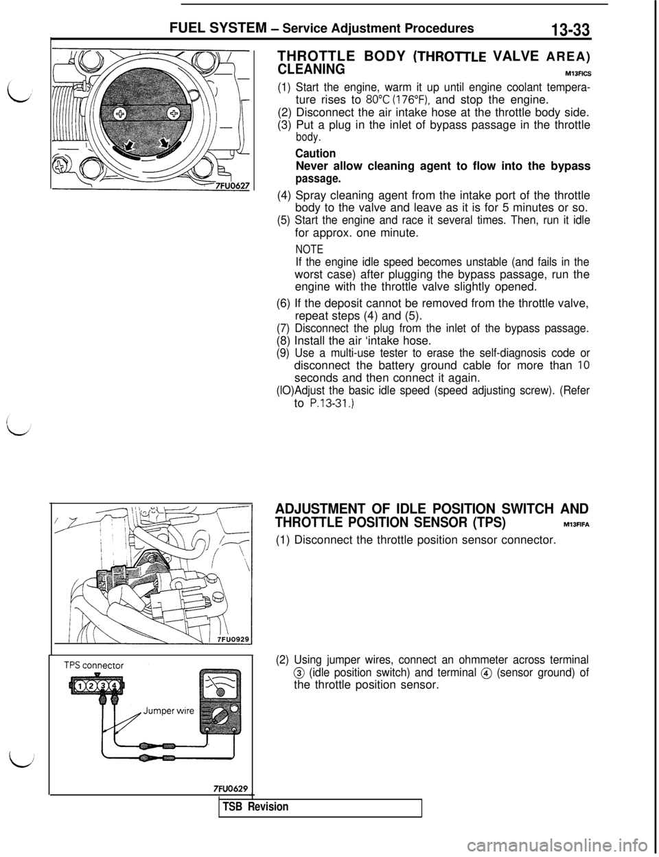
(1) Start the engine, warm it up until engine coolant tempera-ture rises to
80°C (176”F), and stop the engine.
(2) Disconnect the air intake hose at the throttle body side.
(3) Put a plug in the inlet of bypass passage in the throttle
body.
CautionNever allow cleaning agent to flow into the bypass
passage.(4) Spray cleaning agent from the intake port of the throttle
body to the valve and leave as it is for 5 minutes or so.
(5) Start the engine and race it several times. Then, run it idlefor approx. one minute.
NOTE
If the engine idle speed becomes unstable (and fails in theworst case) after plugging the bypass passage, run the
engine with the throttle valve slightly opened.
(6) If the deposit cannot be removed from the throttle valve,
repeat steps (4) and (5).
(7) Disconnect the plug from the inlet of the bypass passage.(8) Install the air ‘intake hose.
(9) Use a multi-use tester to erase the self-diagnosis code ordisconnect the battery ground cable for more than
IOseconds and then connect it again.
(lO)Adjust the basic idle speed (speed adjusting screw). (Referto
P.13-31.)
7FUO629
ADJUSTMENT OF IDLE POSITION SWITCH AND
THROTTLE POSITION SENSOR (TPS)M13FIFA(1) Disconnect the throttle position sensor connector.
(2) Using jumper wires, connect an ohmmeter across terminal
@ (idle position switch) and terminal @ (sensor ground) ofthe throttle position sensor.
TSB Revision
Page 244 of 1146
13438FUEL SYSTEM - On-vehicle Inspection of MPI ComponentsI/
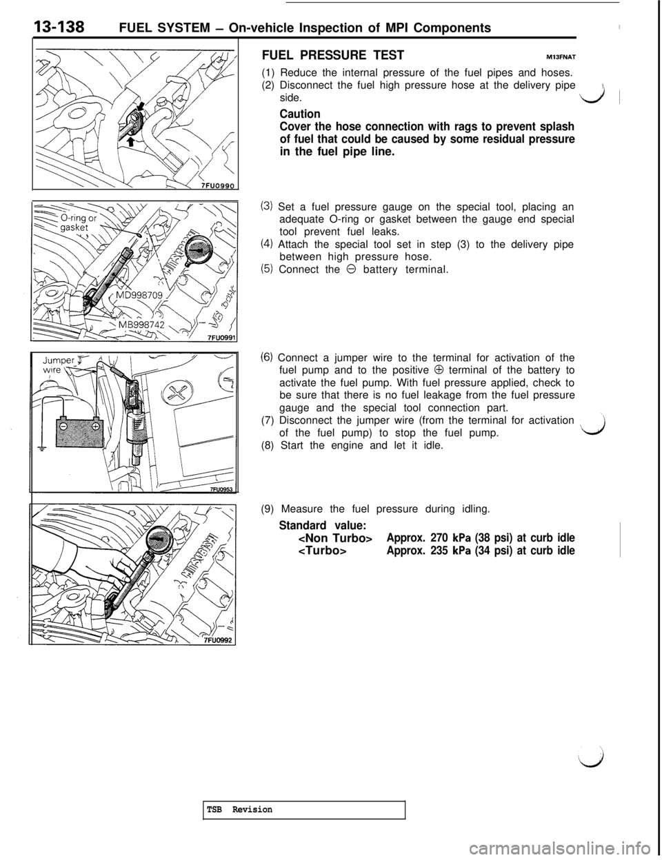
FUEL PRESSURE TESTMlJFNAT(1) Reduce the internal pressure of the fuel pipes and hoses.
(2) Disconnect the fuel high pressure hose at the delivery pipe
side.
dl
Caution
Cover the hose connection with rags to prevent splash
of fuel that could be caused by some residual pressurein the fuel pipe line.
(3) Set a fuel pressure gauge on the special tool, placing an
adequate O-ring or gasket between the gauge end special
tool prevent fuel leaks.
(4) Attach the special tool set in step (3) to the delivery pipe
between high pressure hose.
(5) Connect the 0 battery terminal.
(6) Connect a jumper wire to the terminal for activation of the
fuel pump and to the positive
0 terminal of the battery to
activate the fuel pump. With fuel pressure applied, check to
be sure that there is no fuel leakage from the fuel pressure
gauge and the special tool connection part.
(7) Disconnect the jumper wire (from the terminal for activation
’of the fuel pump) to stop the fuel pump.
(8) Start the engine and let it idle.
d(9) Measure the fuel pressure during idling.
Standard value:
Approx. 270 kPa (38 psi) at curb idle
Approx. 235 kPa (34 psi) at curb idle
TSB Revision
Page 318 of 1146
INTAKE AND EXHAUST - Service Adiustment Procedures
SUPERCHARGING PRESSURE RELIEF SOLENOID
VALVE INSPECTION (Turbo)
OPERATION INSPECTION
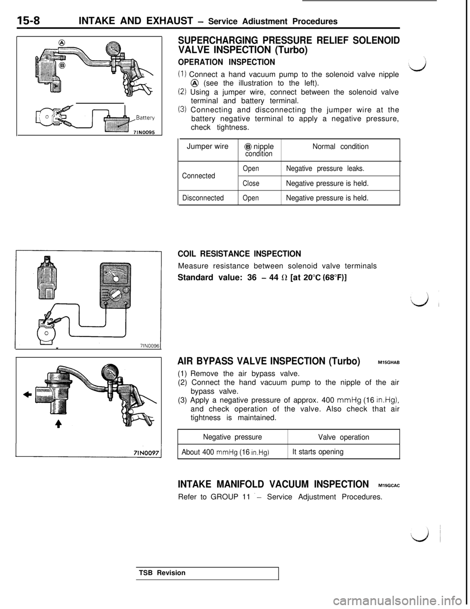
(1) Connect a hand vacuum pump to the solenoid valve nipple@ (see the illustration to the left).
(2) Using a jumper wire, connect between the solenoid valve
terminal and battery terminal.
(3) Connecting and disconnecting the jumper wire at the
battery negative terminal to apply a negative pressure,
check tightness.
Jumper wire
@I nippleNormal conditioncondition
Connected
Disconnected
OpenNegative pressure leaks.
CloseNegative pressure is held.
OpenNegative pressure is held.
COIL RESISTANCE INSPECTIONMeasure resistance between solenoid valve terminals
Standard value: 36
- 44 0 [at 20°C (68”F)I
AIR BYPASS VALVE INSPECTION (Turbo)MlSGHAB
(1) Remove the air bypass valve.
(2) Connect the hand vacuum pump to the nipple of the air
bypass valve.
(3) Apply a negative pressure of approx. 400 mmHg (16
in.Hg),and check operation of the valve. Also check that air
tightness is maintained.
Negative pressure
About 400
mmHg (16 in.Hg)
Valve operation
It starts opening
INTAKE MANIFOLD VACUUM INSPECTIONM’ISGCACRefer to GROUP 11
‘- Service Adjustment Procedures.
TSB Revision
Page 784 of 1146
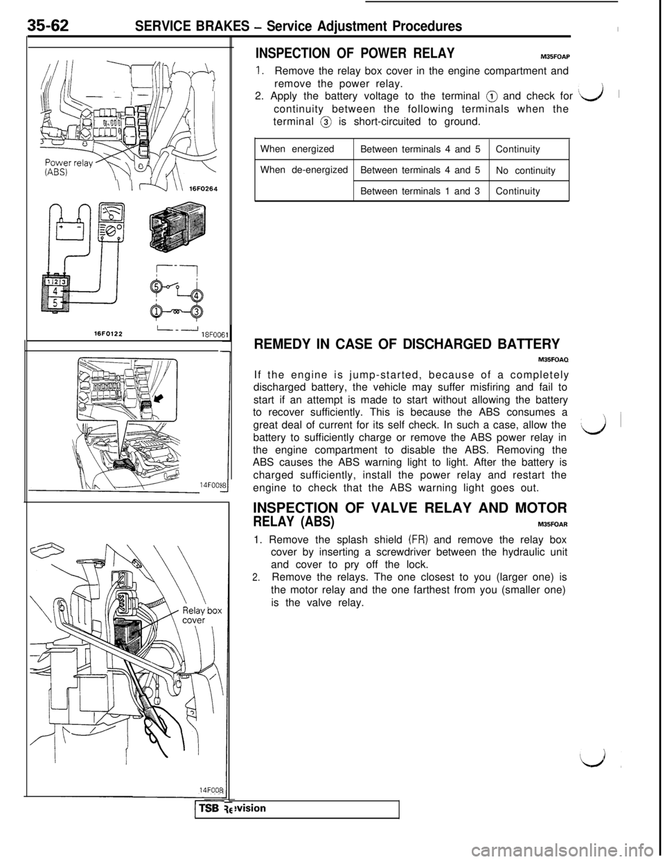
When energized
Between terminals 4 and 5Continuity
When de-energized
Between terminals 4 and 5\i fl \\ 16FO264No continuity
Between terminals 1 and 3Continuity
16FO122L--J18FOCII
SERVICE BRAKES - Service Adjustment ProceduresI
INSPECTION OF POWER RELAYM35FOAP
7
1.Remove the relay box cover in the engine compartment and
remove the power relay.
2. Apply the battery voltage to the terminal @ and check for
‘L-J1
continuity between the following terminals when the
terminal @ is short-circuited to ground.
35-62
14FOOS14FOO8
l-TSB
1
REMEDY IN CASE OF DISCHARGED BATTERY
M35FOAQIf the engine is jump-started, because of a completely
discharged battery, the vehicle may suffer misfiring and fail to
start if an attempt is made to start without allowing the battery
to recover sufficiently. This is because the ABS consumes a
great deal of current for its self check. In such a case, allow the
battery to sufficiently charge or remove the ABS power relay in
the engine compartment to disable the ABS. Removing the
ABS causes the ABS warning light to light. After the battery is
charged sufficiently, install the power relay and restart the
engine to check that the ABS warning light goes out.
INSPECTION OF VALVE RELAY AND MOTOR
RELAY (ABS)M35FOAR1. Remove the splash shield
(FR) and remove the relay box
cover by inserting a screwdriver between the hydraulic unit
and cover to pry off the lock.
2.Remove the relays. The one closest to you (larger one) is
the motor relay and the one farthest from you (smaller one)
is the valve relay.
‘d~ i
wision