relay MITSUBISHI 3000GT 1992 2.G Workshop Manual
[x] Cancel search | Manufacturer: MITSUBISHI, Model Year: 1992, Model line: 3000GT, Model: MITSUBISHI 3000GT 1992 2.GPages: 738, PDF Size: 35.06 MB
Page 498 of 738
Downloaded from www.Manualslib.com manuals search engine 54-2
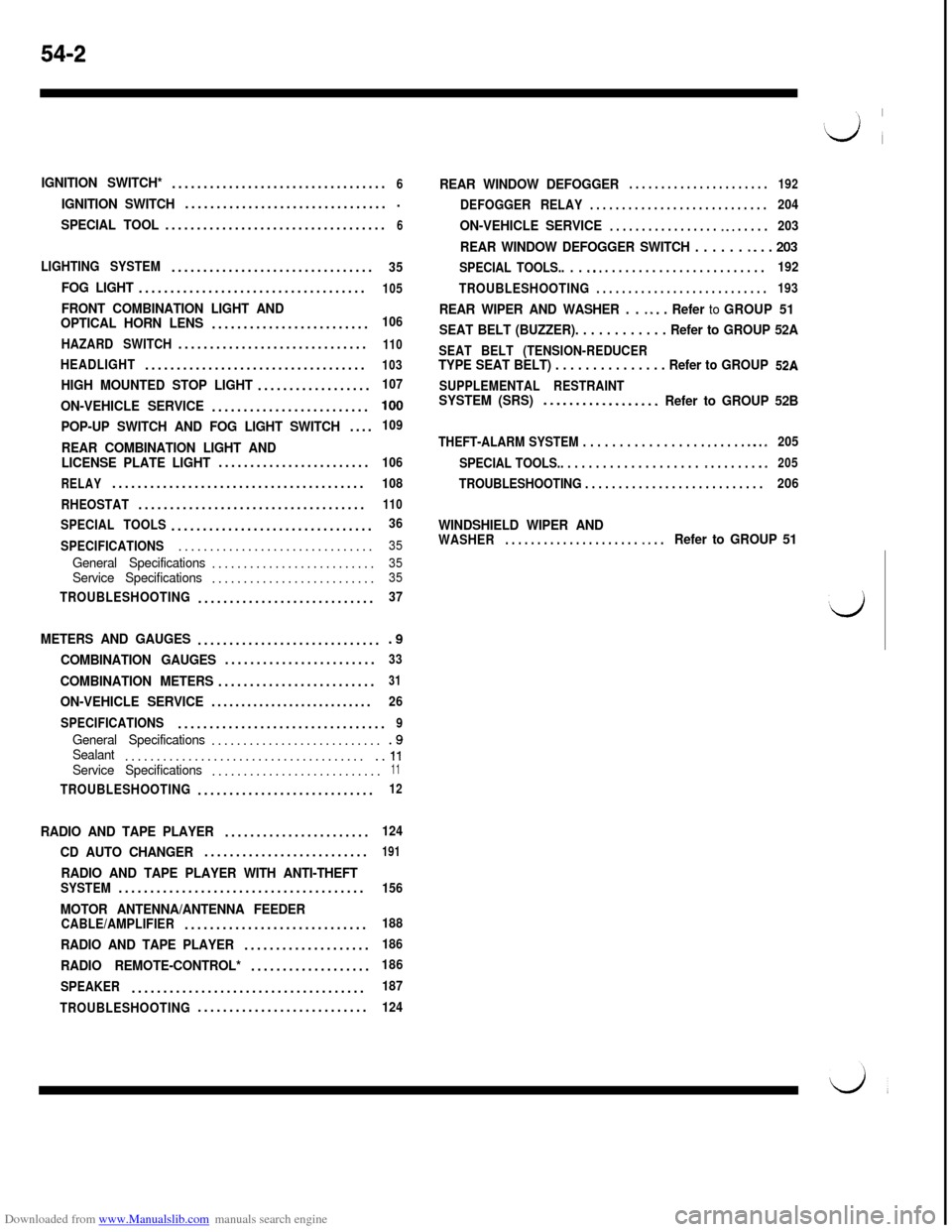
IGNITION SWITCH*..................................6
IGNITION SWITCH.................................
SPECIAL TOOL...................................6
LIGHTING SYSTEM................................35
FOG LIGHT....................................105
FRONT COMBINATION LIGHT AND
OPTICAL HORN LENS.........................106
HAZARD SWITCH..............................
110
HEADLIGHT...................................103
HIGH MOUNTED STOP LIGHT..................107
ON-VEHICLE SERVICE.........................100
POP-UP SWITCH AND FOG LIGHT SWITCH....109
REAR COMBINATION LIGHT AND
LICENSE PLATE LIGHT........................106
RELAY........................................108
RHEOSTAT....................................
110
SPECIAL TOOLS................................36
SPECIFICATIONS...............................
35
General Specifications..........................35Service Specifications..........................35
TROUBLESHOOTING............................37
METERS AND GAUGES..............................9
COMBINATION GAUGES........................33
COMBINATION METERS.........................31
ON-VEHICLE SERVICE...........................26
SPECIFICATIONS.................................
9
General Specifications............................9Sealant........................................ll
Service Specifications...........................11
TROUBLESHOOTING............................12
RADIO AND TAPE PLAYER.......................124
CD AUTO CHANGER..........................191
RADIO AND TAPE PLAYER WITH ANTI-THEFTSYSTEM.......................................156
MOTOR ANTENNA/ANTENNA FEEDERCABLE/AMPLIFIER.............................188
RADIO AND TAPE PLAYER....................186
RADIO REMOTE-CONTROL*...................186
SPEAKER.....................................
187
TROUBLESHOOTING...........................
124
REAR WINDOW DEFOGGER. . . . . . . . . . . . . . . . . . . . . .192
DEFOGGER RELAY. . . . . . . . . . . . . . . . . . . . . . . . . . . .204
ON-VEHICLE SERVICE. . . . . . . . . . . . . . . . . ~ ~. . . . . .203
REAR WINDOW DEFOGGER SWITCH . . . . . . -. . . 203
SPECIAL TOOLS.. . . s.. . . . . . . . . . . . . . . . . . . . . . . . .192
TROUBLESHOOTING
. . . . . . . . . . . . . . . . . . . . . . . . . . .193
REAR WIPER AND WASHER . . ~ *. . Refer to GROUP 51
SEAT BELT (BUZZER). . . . . . . . . . . . Refer to GROUP 52A
SEAT BELT (TENSION-REDUCERTYPE SEAT BELT) . . . . . . . . . . . . . . . Refer to GROUP 52A
SUPPLEMENTAL RESTRAINTSYSTEM (SRS)..-...............Refer to GROUP 52B
THEFT-ALARM SYSTEM . . . . . . . . . . . . . . . . . e . . . . . m.. s205
SPECIAL TOOLS.. . . . . . . . . . . . . . . . . . . .
m . . . . . . . .e205
TROUBLESHOOTING . . . . . . . . . . . . . . . . . . . . . . . . . . .206
WINDSHIELD WIPER ANDWASHER. . . . . . . . . . . . . . . . . . . . . ~. . .Refer to GROUP 51
Page 517 of 738
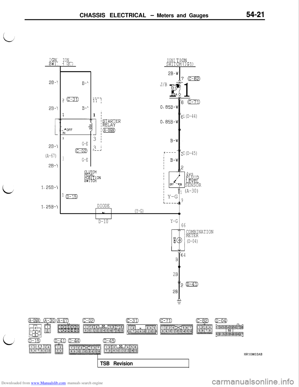
Downloaded from www.Manualslib.com manuals search engine CHASSIS ELECTRICAL - Meters and Gauges54-21
L
IGN:IONsw1:-I (ST)IGNISWIT
2B-'
2B-IB-‘
z(c-31)
B-‘
1
_--11 1
J/B
r
G
151
2B-I
i
2B-I
(A-67)
2B-1
1.25B-\
1.25B-\11
/
1
kTARTERIRELAY.'OFFINim
3
G-E3 /
(c-02)3 i.--J
3G-E
EK”&#ON
l(D-15)
DIODE
E0.85B-'w
E0.85B-'
B-1r----
Ic
1 B-1IIIE
II4wsIIEW1OFF '*ON SENSORII
j Y-G
*q (A-30)
9L----~\
IN(IGl)
'(c-82)
1
i(c-71)
i(D-44)
I(D-45)
L
u(Y-G)0
D-10Y-G
66
COMBINATION
METER
(D-04)
64B
2B
1p(D-41)
28
(A-09X) (A-30)@%?')(c-02)(c-31)(c-71)(C-82)0
/
HRlOM03AB
TSB Revision
Page 519 of 738
Downloaded from www.Manualslib.com manuals search engine LJ
/
:i:CHASSIS ELECTRICAL
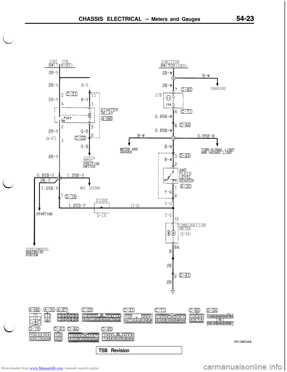
- Meters and Gauges54-23
IGNISWI?
2B-k
2B-k
2B-k
r
2B-Y
(A-67)
2B-Y
jTARTING
SUPPLEMENTALl@TE"#'NT
IONH(ST)
B-YI
z(c-31)17-1
4B-Y I1 /
f
/STARTER--------__;RELAYsPOFFINjm
CLUTCH
PEDAL
&j+$HON
1.25B-Y
IMFI SYSTEM
IGNITIONSWITCH(IG1)I
CHARGING
J/B
s(c-71)
0.85B-W
Y
s(D-44)
0.85B-W
lmDIODE
1.25B-Yu(Y-G)Y-G0
D-10Y-G
66
A COMBINATIONMETER90(D-04)
HRlOMOIAB
TSB Revision
Page 533 of 738
Downloaded from www.Manualslib.com manuals search engine CHASSIS ELECTRICAL - Lighting System54-37
i
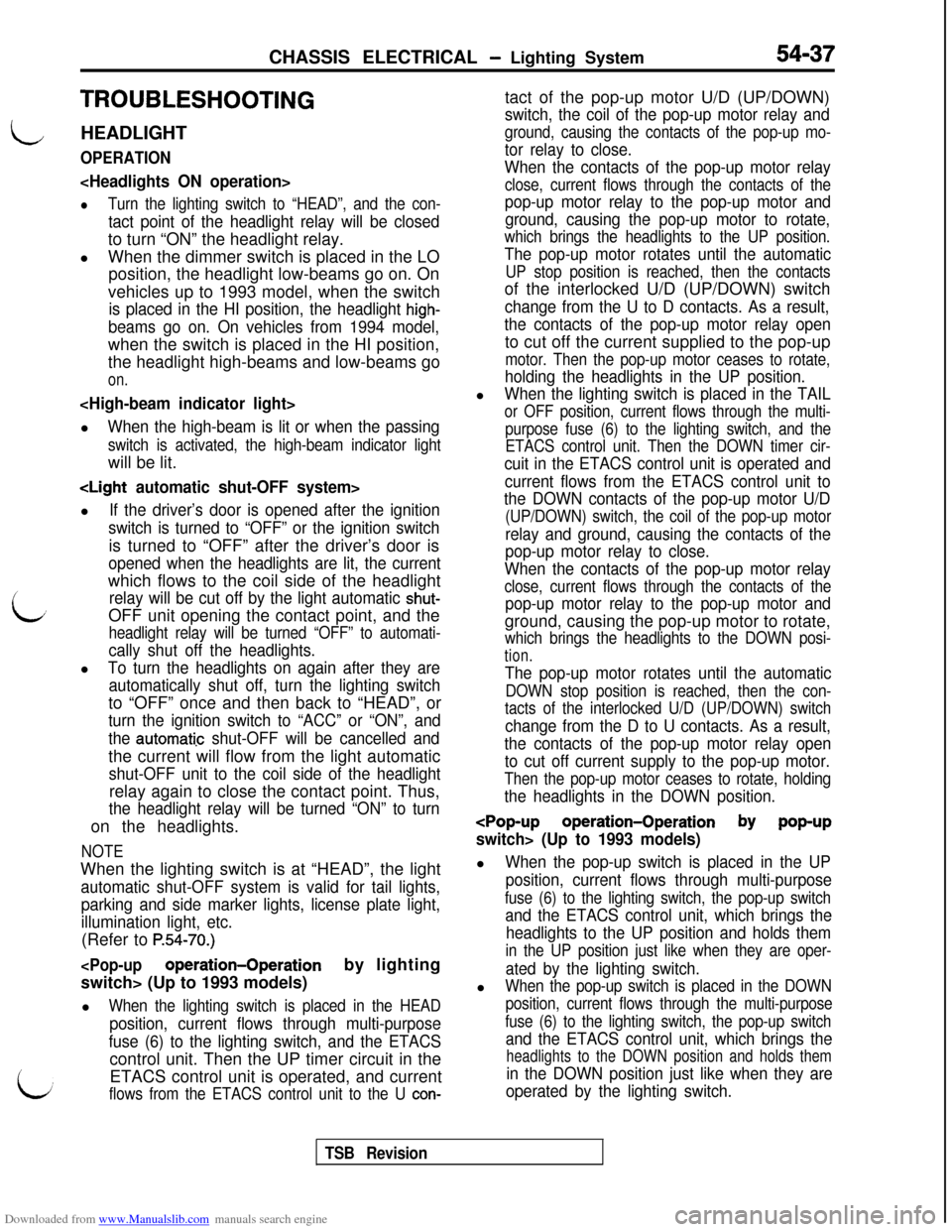
TROUBLESHOOTING
LHEADLIGHT
OPERATION
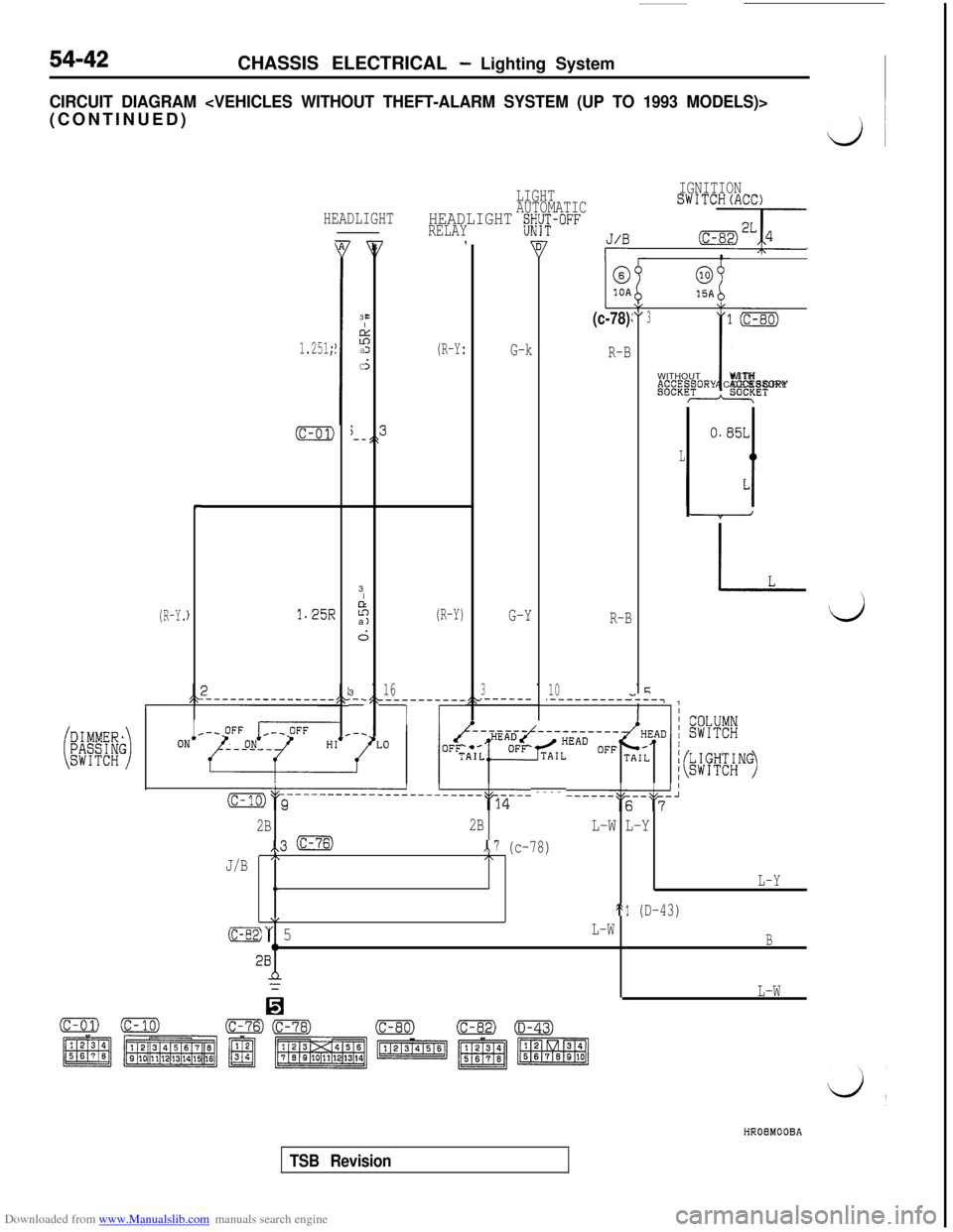
lTurn the lighting switch to “HEAD”, and the con-
tact point of the headlight relay will be closedto turn “ON” the headlight relay.
lWhen the dimmer switch is placed in the LO
position, the headlight low-beams go on. On
vehicles up to 1993 model, when the switch
is placed in the HI position, the headlight high-
beams go on. On vehicles from 1994 model,when the switch is placed in the HI position,
the headlight high-beams and low-beams go
on.
When the high-beam is lit or when the passing
switch is activated, the high-beam indicator lightwill be lit.
If the driver’s door is opened after the ignition
switch is turned to “OFF” or the ignition switchis turned to “OFF” after the driver’s door is
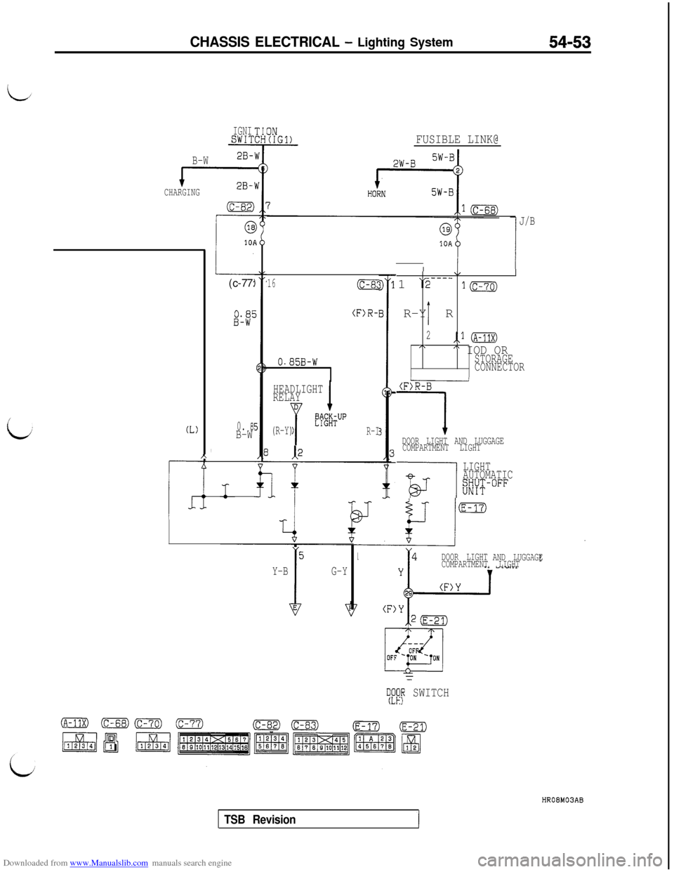
opened when the headlights are lit, the currentwhich flows to the coil side of the headlight
relay will be cut off by the light automatic shut-OFF unit opening the contact point, and the
headlight relay will be turned “OFF” to automati-
cally shut off the headlights.l
To turn the headlights on again after they are
automatically shut off, turn the lighting switchto “OFF” once and then back to “HEAD”, or
turn the ignition switch to “ACC” or “ON”, and
the
aut0mati.c shut-OFF will be cancelled andthe current will flow from the light automatic
shut-OFF unit to the coil side of the headlightrelay again to close the contact point. Thus,
the headlight relay will be turned “ON” to turnon the headlights.
NOTEWhen the lighting switch is at “HEAD”, the light
automatic shut-OFF system is valid for tail lights,
parking and side marker lights, license plate light,
illumination light, etc.(Refer to
P.54-70.)
l
When the lighting switch is placed in the HEAD
position, current flows through multi-purpose
fuse (6) to the lighting switch, and the ETACScontrol unit. Then the UP timer circuit in the
LETACS control unit is operated, and currentflows from the ETACS control unit to the U con-tact of the pop-up motor U/D (UP/DOWN)
switch, the coil of the pop-up motor relay and
ground, causing the contacts of the pop-up mo-
tor relay to close.
When the contacts of the pop-up motor relay
close, current flows through the contacts of the
pop-up motor relay to the pop-up motor and
ground, causing the pop-up motor to rotate,
which brings the headlights to the UP position.
The pop-up motor rotates until the automatic
UP stop position is reached, then the contactsof the interlocked U/D (UP/DOWN) switch
change from the U to D contacts. As a result,
the contacts of the pop-up motor relay opento cut off the current supplied to the pop-up
motor. Then the pop-up motor ceases to rotate,
holding the headlights in the UP position.l
When the lighting switch is placed in the TAIL
or OFF position, current flows through the multi-
purpose fuse (6) to the lighting switch, and the
ETACS control unit. Then the DOWN timer cir-
cuit in the ETACS control unit is operated and
current flows from the ETACS control unit to
the DOWN contacts of the pop-up motor U/D
(UP/DOWN) switch, the coil of the pop-up motor
relay and ground, causing the contacts of the
pop-up motor relay to close.
When the contacts of the pop-up motor relay
close, current flows through the contacts of the
pop-up motor relay to the pop-up motor andground, causing the pop-up motor to rotate,
which brings the headlights to the DOWN posi-
tion.
The pop-up motor rotates until the automatic
DOWN stop position is reached, then the con-
tacts of the interlocked U/D (UP/DOWN) switch
change from the D to U contacts. As a result,
the contacts of the pop-up motor relay open
to cut off current supply to the pop-up motor.
Then the pop-up motor ceases to rotate, holding
the headlights in the DOWN position.
When the pop-up switch is placed in the UP
position, current flows through multi-purpose
fuse (6) to the lighting switch, the pop-up switch
and the ETACS control unit, which brings the
headlights to the UP position and holds them
in the UP position just like when they are oper-
ated by the lighting switch.l
When the pop-up switch is placed in the DOWN
position, current flows through the multi-purpose
fuse (6) to the lighting switch, the pop-up switch
and the ETACS control unit, which brings the
headlights to the DOWN position and holds them
in the DOWN position just like when they are
operated by the lighting switch.
TSB Revision
Page 535 of 738
Downloaded from www.Manualslib.com manuals search engine CHASSIS ELECTRICAL - Lighting System54-39
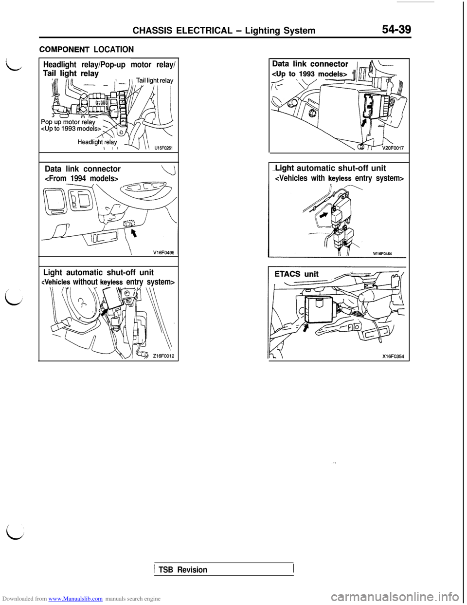
ZOMPONENT LOCATION
Headlight relay/Pop-up motor relay/
HeadliiW,$w, q\\ u,6F026,
Data link connector
\V16FO49E
Light automatic shut-off unit
-Light automatic shut-off unit
i
1 TSB Revision
Page 538 of 738
Downloaded from www.Manualslib.com manuals search engine 54-42CHASSIS ELECTRICAL - Lighting System
CIRCUIT DIAGRAM
(R-Y.
HEADLIGHT
1.251;
(c-01)j-_,\
L
c
)1.25R
B3
EI
z:aJ
C5
LIGHTIGNITION
AUTOMATICSWITCH(ACC)
HEADLIGHT gWi-i;-OFFRELAY7,J/B -7
(R-Y:I
@0
10A15AY(c-78)\I:3
G-k
R-BWITHOUTP.~~“.~~ORY
-3
I
P;
a(R-Y)G-YR-B
i;3
16310.-_.------.-----------
7 r
-__-7
(c-01)
l(c-80)
iWITH
ACCESSORY*ET
m&c-----------------------~q-6-- ---- ------""s--"F-'
2B2BL-W L-Y
,,3 mx.7 (c-78)
J/B/\I\
t.L-Y
\/St1 (D-43)
(c-82)“ 5L-W
0B28n
0
L-W
HROEMOOBA
TSB Revision
Page 549 of 738
Downloaded from www.Manualslib.com manuals search engine CHASSIS ELECTRICAL - Lighting System54-53
IGNISWIT
B-W2B-
CHARGING
(L)
r_c
A-
I(c-77:
0. 8!B-W
,
FUSIBLE LINK@
16(c-8c
(F)R-
0.85B-W
HEADLIGHT
RELAY
D
Y
&m&UP
(R-Y)R-I
5
I
G-Y Y-B
10AI
r!
J/B
\/I1
\2---_
1mR-Y R
I
2,.l (A-11x)I\A IOD ORSTORAGE
CONNECTOR
(F)R-B
1DOOR LIGHT AND LUGGAGE
COMPARTMENT LIGHT
-is---l
LIGHT
AUTOMATIC
Kw°FF
DOOR LIGHT
AND LUGGAGE
COMPARTMENT LIGHT
--
s!fip SWITCHHROBMOSAB
TSB Revision
Page 554 of 738
Downloaded from www.Manualslib.com manuals search engine 54-58CHASSIS ELECTRICAL - Lighting System
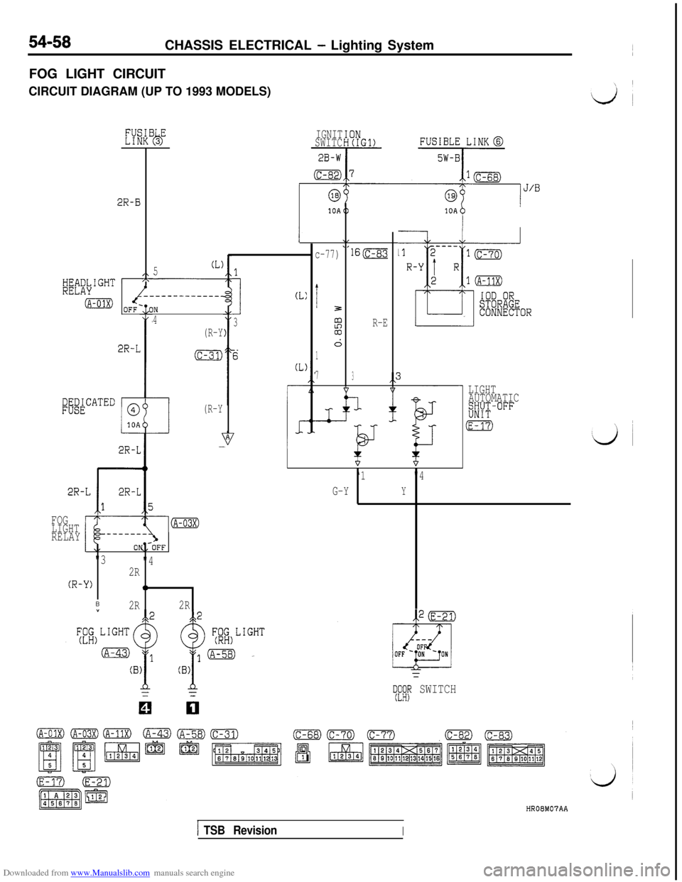
FOG LIGHT CIRCUIT
CIRCUIT DIAGRAM (UP TO 1993 MODELS)
2R-B
,\
-------------_
OFF-10IN
4
(R-Y
(c-31)2R-L
PWATED
c
@
10A
(R-Y
2R-L
2R-L
r
2R-L
1
5(L)
FOG
LIGHT
RELAY
(R-
"3
"4
2R
-Y)0
B2R2RIGNIT
SWITC
2B-W
(c-82)
1
I
CL:
3
c-77)
i3
%03
d
1
7lS(c-83
R-E
3
-L
10A
P
- LIGHT
AUTOMATIC
w-°FF
(E-
‘1"4
G-Y
Y
TeKIp SWITCHHROEM07AA
ITSB RevisionI
Page 555 of 738
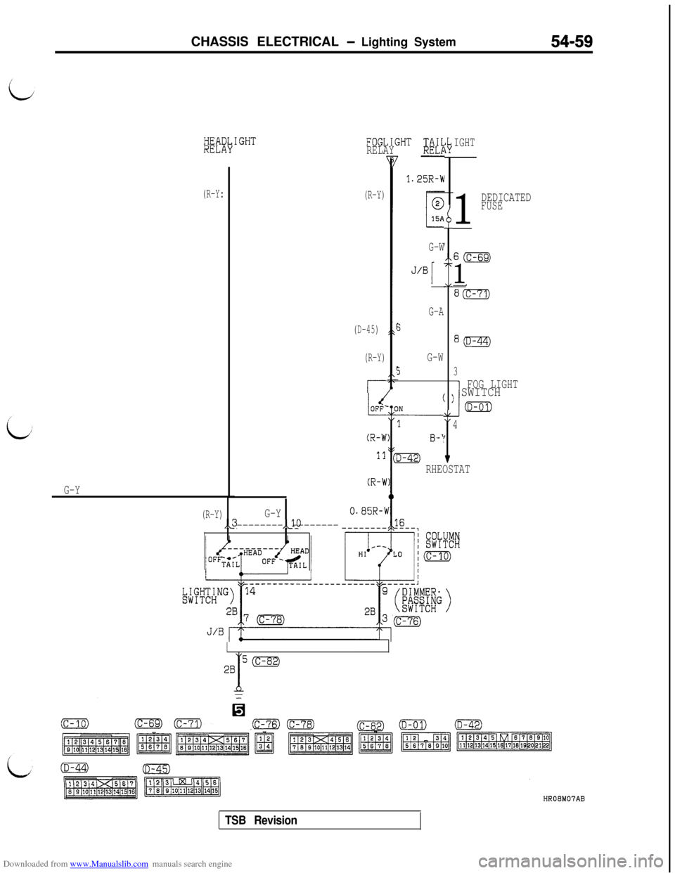
Downloaded from www.Manualslib.com manuals search engine CHASSIS ELECTRICAL - Lighting System54-59
~~if\IGHTFOGLIGHT ;N;RELAYIGHT
(R-Y)
(D-45)
(R-Y)
r-
1.25R-W
1
DEDICATEDFUSE
(R-Y:
G-Y
I
Ib
I
G-W60
1
G-A
5
G-W
53I
FOG LIGHT) SWITCH
(D-al)
I
I
4
RHEOSTAT
(R-Y)G-Y,,3,JO
-------- --------
(c-82)
TSB Revision
Page 558 of 738
Downloaded from www.Manualslib.com manuals search engine 54-62CHASSIS ELECTRICAL - Lighting System
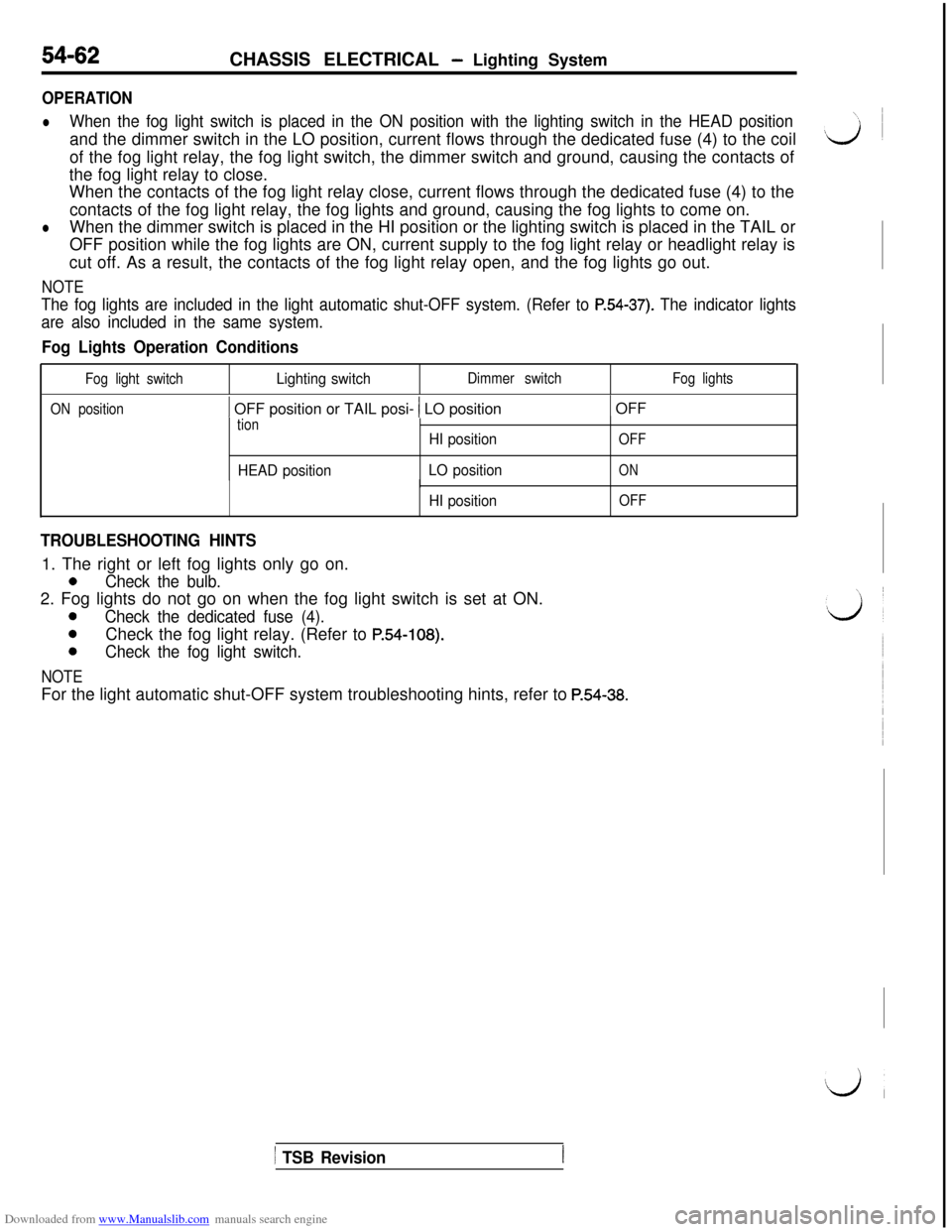
OPERATION
lWhen the fog light switch is placed in the ON position with the lighting switch in the HEAD positionand the dimmer switch in the LO position, current flows through the dedicated fuse (4) to the coil
of the fog light relay, the fog light switch, the dimmer switch and ground, causing the contacts of
the fog light relay to close.
When the contacts of the fog light relay close, current flows through the dedicated fuse (4) to the
contacts of the fog light relay, the fog lights and ground, causing the fog lights to come on.
lWhen the dimmer switch is placed in the HI position or the lighting switch is placed in the TAIL or
OFF position while the fog lights are ON, current supply to the fog light relay or headlight relay is
cut off. As a result, the contacts of the fog light relay open, and the fog lights go out.
NOTE
The fog lights are included in the light automatic shut-OFF system. (Refer to P.54-37). The indicator lights
are also included in the same system.
Fog Lights Operation Conditions
Fog light switchLighting switchDimmer switchFog lights
ON position
1 OFF position or TAIL posi- 1 LO position1 OFF
tion
HEAD positionHI position
LO position
OFF
ON
HI position
I
OFF
TROUBLESHOOTING HINTS1. The right or left fog lights only go on.
0Check the bulb.2. Fog lights do not go on when the fog light switch is set at ON.
0Check the dedicated fuse (4).
0Check the fog light relay. (Refer to P.54-108).
0Check the fog light switch.
NOTEFor the light automatic shut-OFF system troubleshooting hints, refer to
P.54-38.
1 TSB Revision