relay MITSUBISHI 3000GT 1992 2.G Workshop Manual
[x] Cancel search | Manufacturer: MITSUBISHI, Model Year: 1992, Model line: 3000GT, Model: MITSUBISHI 3000GT 1992 2.GPages: 738, PDF Size: 35.06 MB
Page 620 of 738
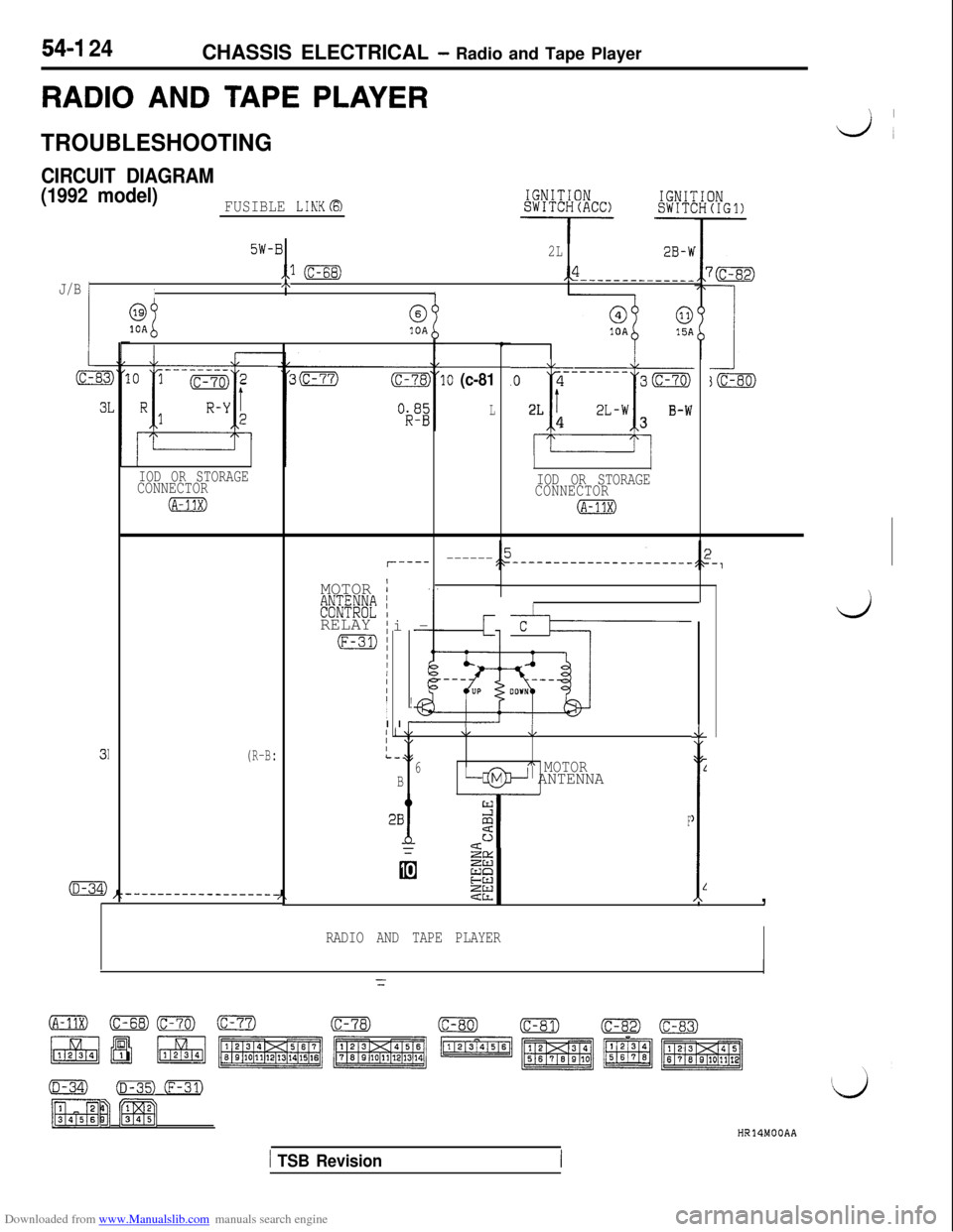
Downloaded from www.Manualslib.com manuals search engine 54-I 24CHASSIS ELECTRICAL - Radio and Tape Player
RADIO AND TAPE PLAYERL.1
TROUBLESHOOTING
CIRCUIT DIAGRAM
(1992 model)
FUSIBLE LINKa
5W-B2L2B-W
,.l (c-68),,4
J/B 1-------_-_____/\II
lOA&10A
----_--_.o 43m
r
2LT2L-wB-W43
.o (c-81
LI
IOD OR STORAGECONNECTOR
(A-31X)
IOD OR STORAGE
CONNECTOR
(A-11X)
r-----------
C
ih----
i
UP :MOTOR
:&g/g~ iRELAY
!i--
!
II
6
(F-31):I/IIII
I
I
d
cII
II I \L\I,4,I \,IL-356xx MOTORB-@+- ANTENNA
2i ‘y-g--
L
F1
6 -is%
E
ZEI ,L
(R-B:
RADIO AND TAPE PLAYER
(A-11X) OEm) (c-7’71(c-78)(c-80)rc-81)(c-82)0
pqpJ ~1~~1~~1~‘~~
(D-34)(D-35) m-3
[%FRj [gqH]HR14MOOAA
1 TSB Revision
Page 624 of 738
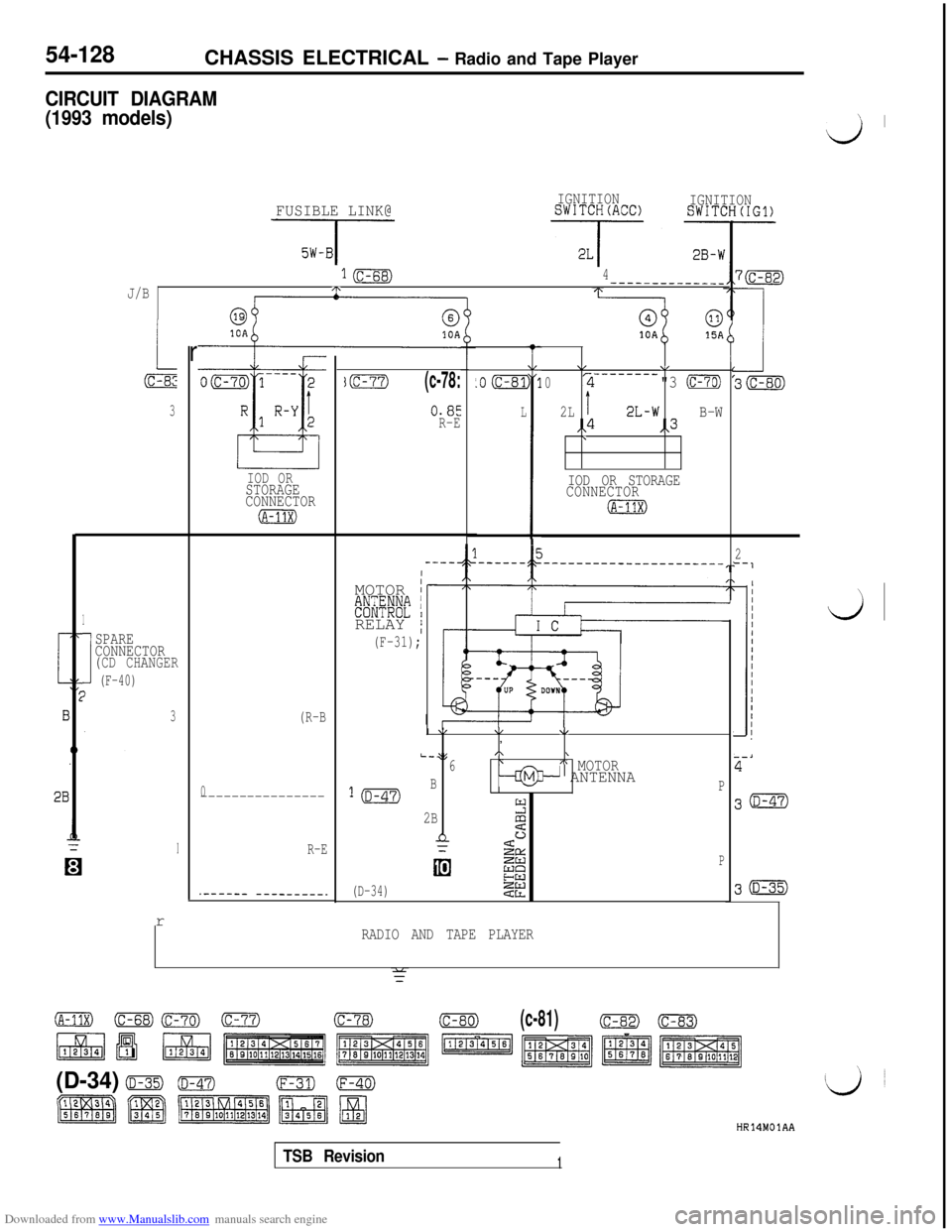
Downloaded from www.Manualslib.com manuals search engine 54-128CHASSIS ELECTRICAL - Radio and Tape Player
CIRCUIT DIAGRAM
(1993 models)
’ I
d
FUSIBLE LINK@
J-
IGNITIONSWITCH(ACC)IGNITIONSWITCH(IG1)
1B4------------__J/B/T\
r
3
1
I
SPARE
CONNECTOR
(CD CHANGER
(F-40)I
3r
IOD ORSTORAGE
CONNECTOR
(A-11x)
(R-B
0----------------
R-E
.------ ---------.
jm(c-78:
0.85
R-E
IMOTOR
I#$@E;'ti IRELAY
/
(F-31);
L
.o (c-81
L
I
11
I
\/V-------_02"3 CmTg
2LI2L-wB-W,,4,,3\
IOD OR STORAGE
CONNECTOR
IA-11X)I
\/\/\I,
L-;(,\\6\A MOTOR
l(D-47)B--@3- ANTENNAP
2B2
n3SaL
EEP
(D-34)22
RADIO AND TAPE PLAYER
f
2‘-1
30
30
d
(A-1Ix) (c-ss)Crn) (c-77)(c-78)(c-80)(c-81)(c-82)-
\
(D-34) o(D-47)(F-31)0
HR14MOlAA
TSB Revision1
Page 664 of 738
Downloaded from www.Manualslib.com manuals search engine 54-168CHASSIS ELECTRICAL - Radio and Tape Player
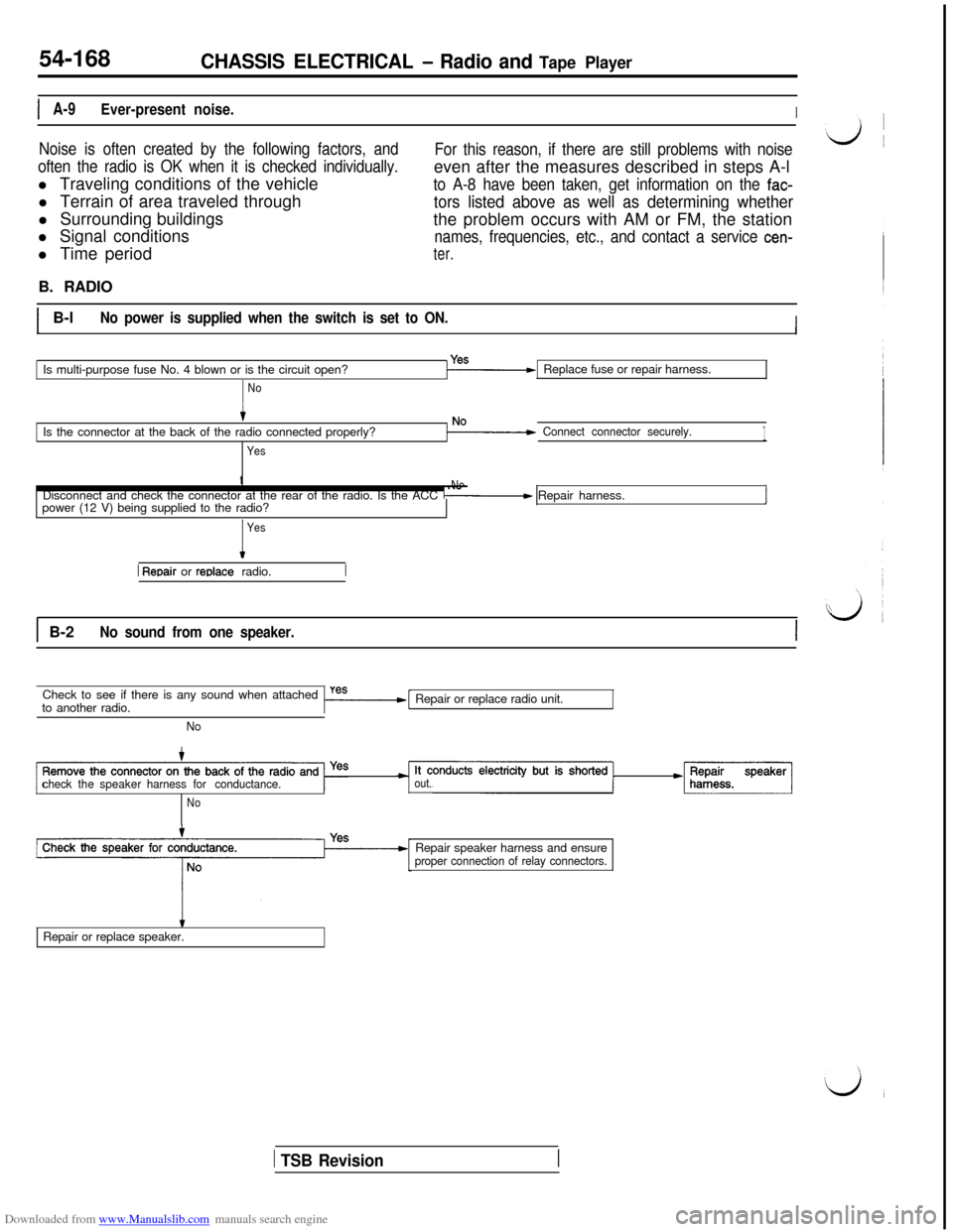
IA-9Ever-present noise.I
Noise is often created by the following factors, and
often the radio is OK when it is checked individually.l Traveling conditions of the vehicle
l Terrain of area traveled through
l Surrounding buildings
l Signal conditions
l Time periodFor this reason, if there are still problems with noiseeven after the measures described in steps A-l
to A-8 have been taken, get information on the fac-
tors listed above as well as determining whetherthe problem occurs with AM or FM, the station
names, frequencies, etc., and contact a service cen-
ter.B. RADIO
IB-lNo power is supplied when the switch is set to ON.IIIIs multi-purpose fuse No. 4 blown or is the circuit open?Replace fuse or repair harness.
NoIs the connector at the back of the radio connected properly?
Yes
Connect connector securely.1t
NoDisconnect and check the connector at the rear of the radio. Is the ACC / Repair harness.
power (12 V) being supplied to the radio?J
I
Yes
1 Reoair or reolace radio.
1 B-2No sound from one speaker.ICheck to see if there is any sound when attached
to another radio.
I-=----[Repair or replace radio unit.
No
checkthespeakerharnessfor conductance.
out.*Speakarj
NoRepair speaker harness and ensure
proper connection of relay connectors.
tRepair or replace speaker.
1 TSB Revision
Page 670 of 738
Downloaded from www.Manualslib.com manuals search engine 54-174
CHASSIS ELECTRICAL - Radio and Tape Player
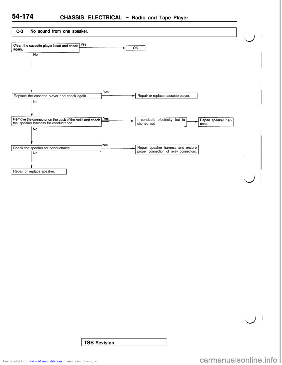
C-3No sound from one speaker.t
YesReplace the cassette player and check again.
NoRepair or replace cassette player.
thespeaker harness for conductance.___c It conducts electricity but isshorted out.
+Check the speaker for conductance.
NoRepair speaker harness and ensureproper connection of relay connectors.
tRepair or replace speaker.
TSB Revision
Page 677 of 738
Downloaded from www.Manualslib.com manuals search engine CHASSIS ELECTRICAL - Radio and Tape Player54-181
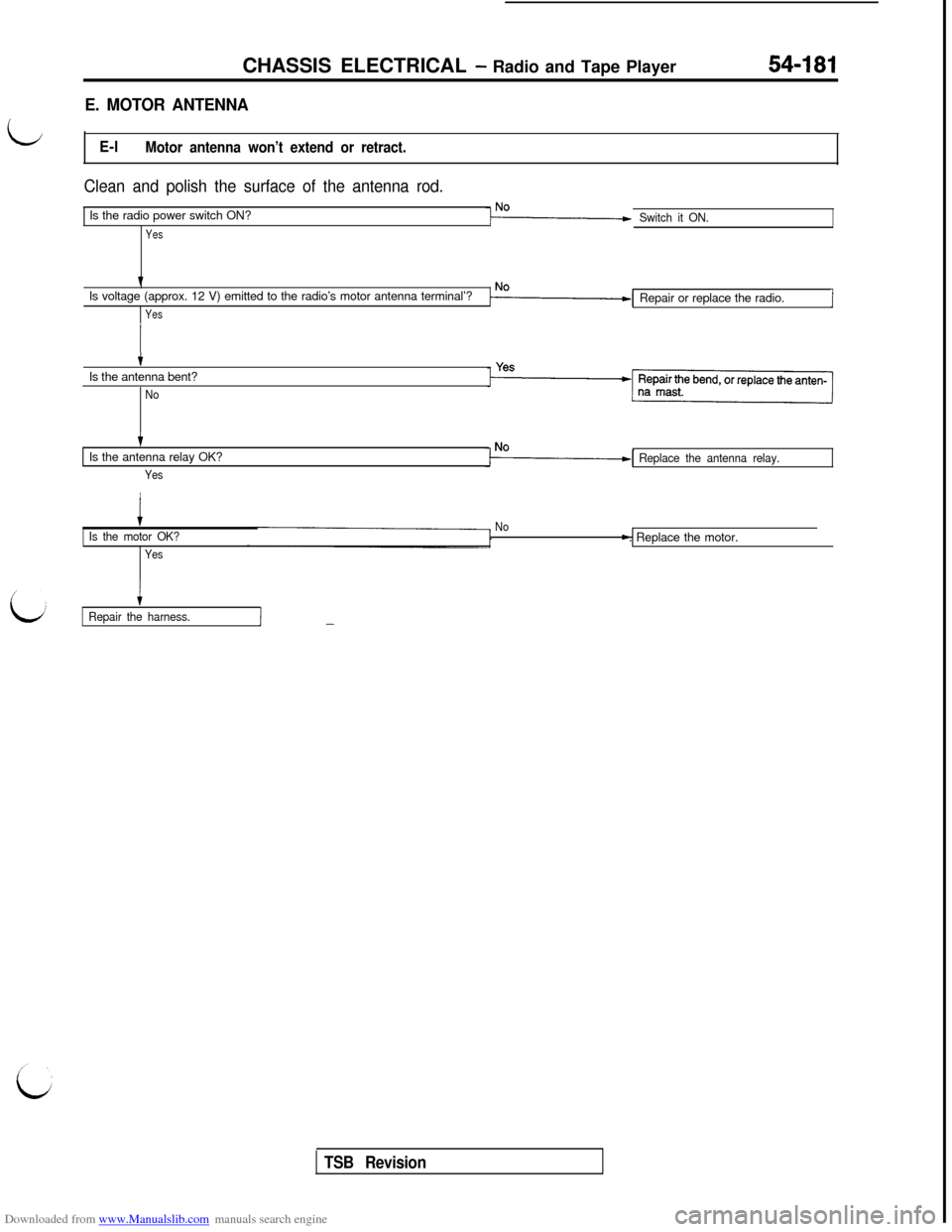
E. MOTOR ANTENNA
LE-lMotor antenna won’t extend or retract.
Clean and polish the surface of the antenna rod.Is the radio power switch ON?
Yes
Switch it ON.Is voltage (approx. 12 V) emitted to the radio’s motor antenna terminal’?
YesRepair or replace the radio.i
tIs the antenna bent?
No
tIs the antenna relay OK?
Yes
Replace the antenna relay.
iIs the motor OK?
YesNo
c
Repair the harness.I-
TSB Revision. Replace the motor.
Page 691 of 738
Downloaded from www.Manualslib.com manuals search engine CHASSIS ELECTRICAL - Rear Window Defogger54-195
5W-B2W-B
HORN5W-B,,l (c-68)J/B
(c-83)-10A
(F)R-B(F>R-E
DOOR LIGHT AND LUGGAGECOMPARTMENT
‘11----__
R-Y
I' R
1ma
21)(A-11X)
i
FUSIBLE LINK@I
.HEADLIGHT.FOG LIGHT.TAILLIGHT
PARKING/SIDE
MARKER LIGHTAND LICENSEPLATE LIGHT
ETACS ECU
B-L
I
R-B
E
2E4
B
1
6
2B-1
IOD OR STRAGECONNECTOR
lOFd,ONIND’I-
TAILLIGH'T RELAY
2R-
Zz&P”‘“”
L
G
15
G-
J/B
I
G-
G-W4
(D-41)F-.ELC-4A/T
'#&AND (G-!'I
2
1ILL
1 *
1
B
16I
2B
I
(D-41)
2
2B
=
H
:;f'g-$;T (B-Y
*G"~$&AND
v
1
3
1
i-
S(c-69)
II
e(c-71)
RHEOSTAT
NOTE:l:VEHICLES WITHOUTTHEFT-ALARM SYSTEM.X2:VEHICLES WITHTHEFT-ALARM SYSTEM.
(C-79)FRONT SIDE (c-83)(D-06)(D-41) (D-42)(D-44)
HR13MOlAB
TSB Revision
Page 692 of 738
Downloaded from www.Manualslib.com manuals search engine 54-196CHASSIS ELECTRICAL - Rear Window Defogger
CIRCUIT DIAGRAM
F'JSIBLELINK@
3R-I3
(c-01)22B-h,-----------___.
3R-E
3B-F
38-F
IGNITIONIGNIlSWITCH(IG2)SWITC
- -
2L-BI
28-h
J’Bp
L-RIB-k
DEFOGGER
RELAY
(c-06x)
MFI SYSTEM3;:(c-66)-
REMOTE#JJ&LLED
GNIn
B
!B
INGENE(IGl)(L TE
B-W(F>I
7mCHARGINGI(D-45)
30
I
e-CHARGINGT
(c-15)
52
TORINAL)
10
'57 :1I
59 $2
NOTE:l:VEHICLES WITHOUTTHEFT-ALARM SYSTEM.22:VEHICLES WITHTHEFT-ALARM SYSTEM.
HR13M02AA
1 TSB Revision
Page 693 of 738
Downloaded from www.Manualslib.com manuals search engine CHASSIS ELECTRICAL - Rear Window Defogger
ii
2W-B
5W-BHORN
‘J/B,.1 (c-68)
(F>R-B(F>R-I
DOOR LIGHT AND LUGGAGE
COMPARTMENT LIGHT
:I,
,HEADLIGHT.FOG LIGHT.TAILLIGHT.PARKING/SIDE
MARKER LIGHT
AND LICENSE
PLATE LIGHT
69
10A\/
11------ A/1R-Y
r R
(c-70)
/L-R
cc-65)
f
i
I
,E
2B
FUSIBLE LINKa
I
1,,2 ,,l/\,--(A-11X) (
2B-F
IOD OR STRAGE
CONNECTOR
DEFOGGER
SWITCH
iD-os)
i
my54
B-L
R-B
9I16"AA\(
45 DATA LINK CONNECTOR
B(c-79)
i
L-R
V
1'4
:;fE-$;T (B-Y).$;;EESAND
2B
,(D-41)B-Y
27
RHEOSTAT
2B
h
n
NOTE:l:VEHICLES WITHOUTTHEFT-ALARM SYSTEM.:2:VEHICLES WITHTHEFT-ALARM SYSTEM.
2B-k
\6
IND(UN
TAILLIGHT RELAY
q-
:;&"A'""
J/B
7L IIG-W
I
8cc-71)
p@
G-W4
Ed.ELC-4A/T
'i;$$SAND (G-W)
2,,3
HR13M02AB
TSB Revision
Page 695 of 738
Downloaded from www.Manualslib.com manuals search engine CHASSIS ELECTRICAL - Rear Window Defogger54-199
LJ
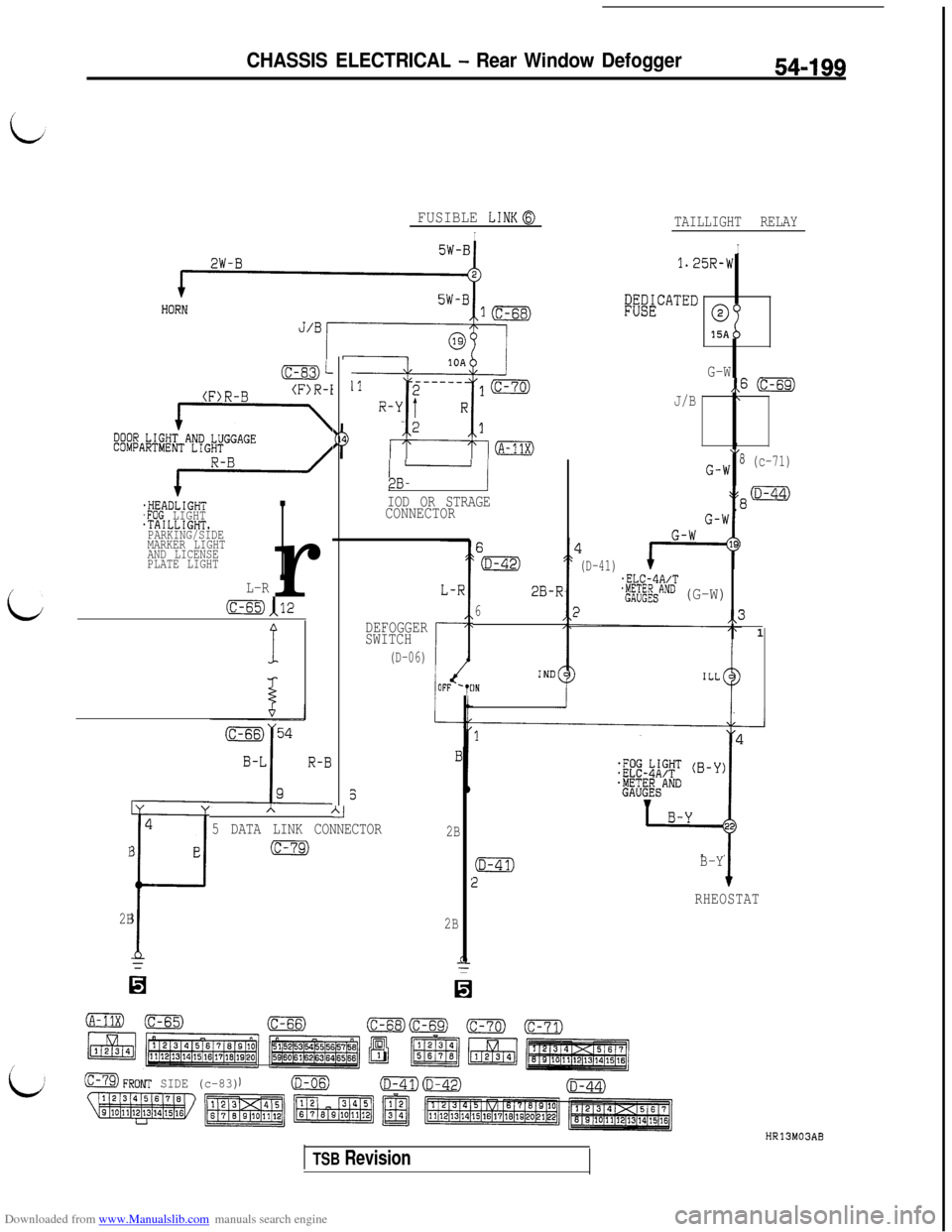
FUSIBLE LINKa
I
(c-83)L
(F>R-B(F>R-i
DOOR LIGHT AND LUGGAGECOMPARTMENF
.HEADLIGHT,FOG LIGHT.TAILLIGHT.PARKING/SIDE
MARKER LIGHT
AND LICENSE
PLATE LIGHTr
IL-R
(C-65)112P
$
4
B
E
F
2B=
/ - 12B-
IOD OR STRAGE
CONNECTOR
DEFOGGER
SWITCH
(D-06)i
Al
5 DATA LINK CONNECTOR
)FF ‘T[
2B
2B
2B-
6
IN
I
TAILLIGHT RELAY
I1.25R-W
l&&CATED
0%
15A
G-W,,6 (c-69)
J/B\
,\,G-W8 (c-71)
W8(D-44)
1
(D-41).ELC-4A/T
'&;&AND (G-W)),,31
:aFRONT SIDE (c-83)
B-Y
RHEOSTAT
HR13M03AB
TSB Revision
Page 696 of 738
Downloaded from www.Manualslib.com manuals search engine 54-200CHASSIS ELECTRICAL - Rear Window Defogger
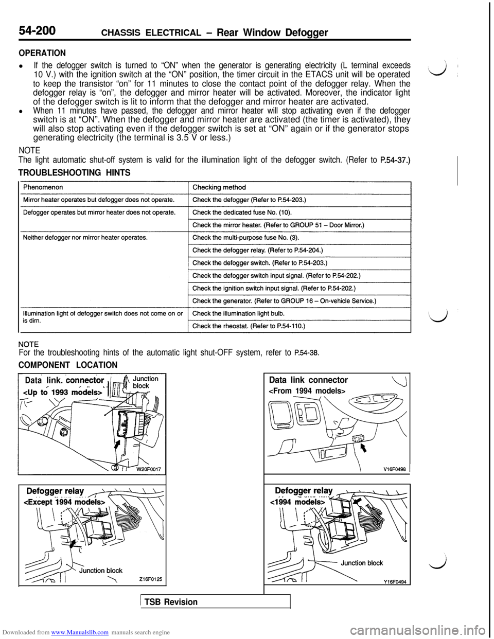
OPERATIONl
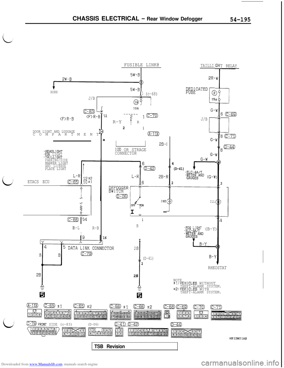
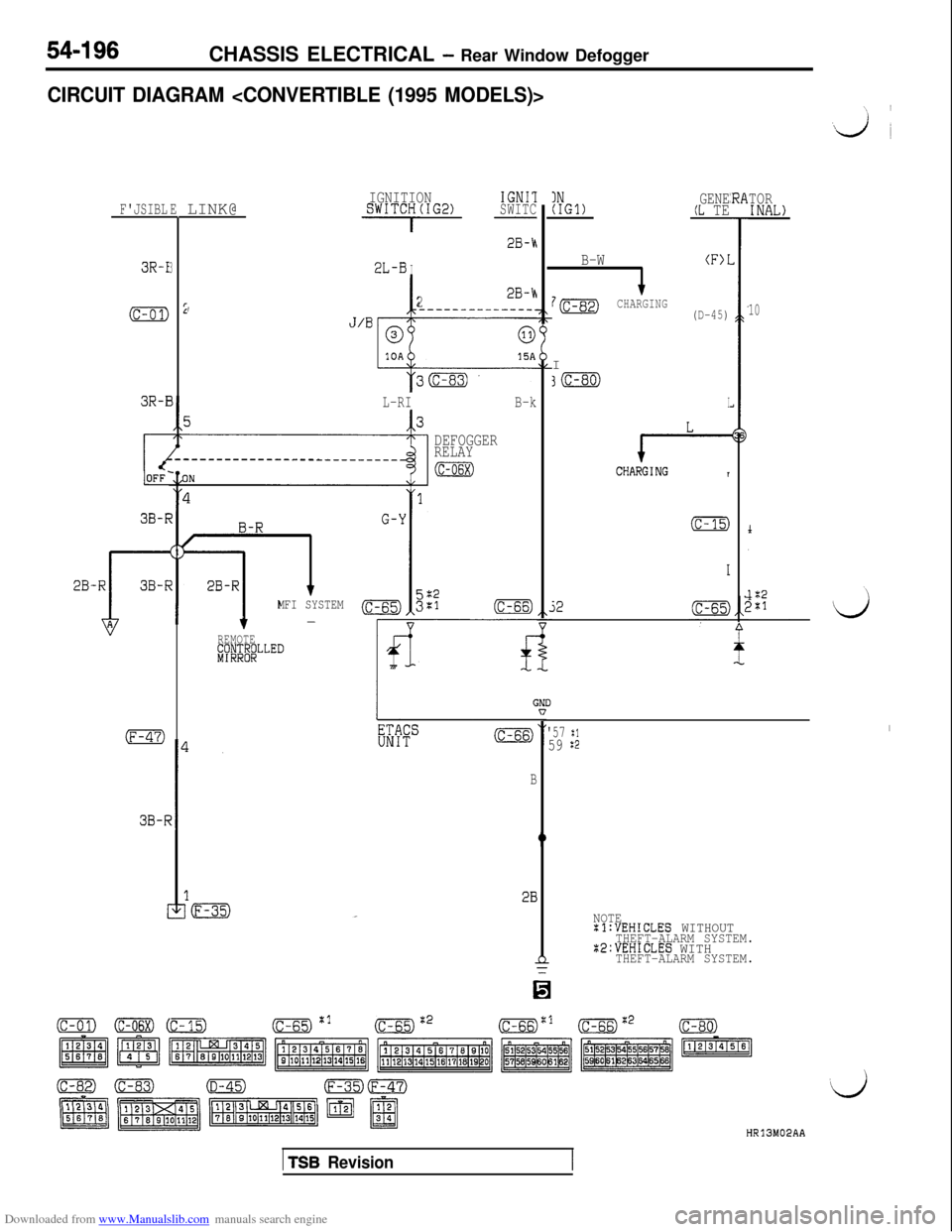
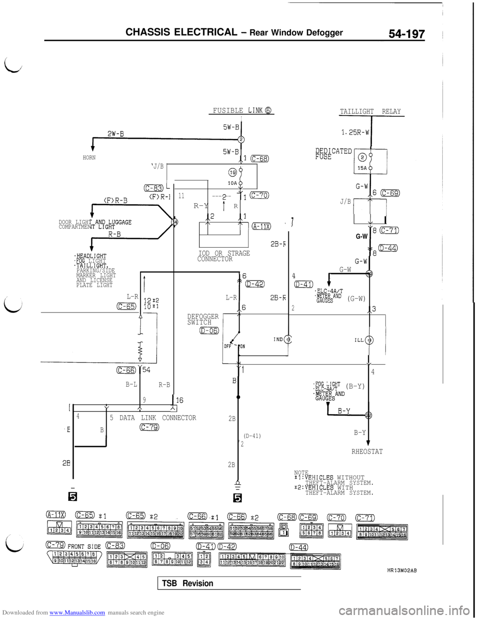
If the defogger switch is turned to “ON” when the generator is generating electricity (L terminal exceeds
10 V.) with the ignition switch at the “ON” position, the timer circuit in the ETACS unit will be operated
to keep the transistor “on” for 11 minutes to close the contact point of the defogger relay. When the
defogger relay is “on”,the defogger and mirror heater will be activated. Moreover, the indicator lightof the defogger switch is lit to inform that the defogger and mirror heater are activated.
lWhen 11 minutes have passed, the defogger and mirror heater will stop activating even if the defoggerswitch is at “ON”. When the defogger and mirror heater are activated (the timer is activated), they
will also stop activating even if the defogger switch is set at “ON” again or if the generator stops
generating electricity (the terminal is 3.5 V or less.)
NOTE
The light automatic shut-off system is valid for the illumination light of the defogger switch. (Refer to
P.54-37.)
TROUBLESHOOTING HINTS
NOTE
For the troubleshooting hints of the automatic light shut-OFF system, refer to P.54-38.
COMPONENT LOCATION
Datalink. connector
216FO125
Data link connector
\V16FO496 1
es.-‘) blocky,6Fww
1 TSB Revision