relay MITSUBISHI 3000GT 1992 2.G Workshop Manual
[x] Cancel search | Manufacturer: MITSUBISHI, Model Year: 1992, Model line: 3000GT, Model: MITSUBISHI 3000GT 1992 2.GPages: 738, PDF Size: 35.06 MB
Page 559 of 738
Downloaded from www.Manualslib.com manuals search engine CHASSIS ELECTRICAL - Lighting System
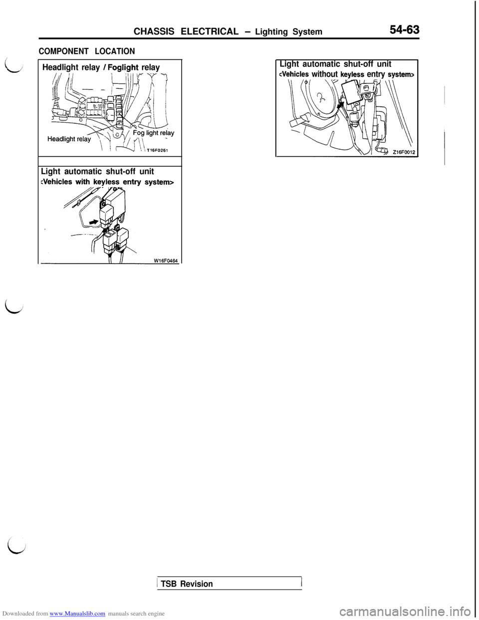
COMPONENT LOCATION
54-63
Headlight relay / Foglight relay
Light automatic shut-off unitLight automatic shut-off unit
1 TSB Revision
Page 562 of 738
Downloaded from www.Manualslib.com manuals search engine 54-66CHASSIS ELECTRICAL - Lighting System
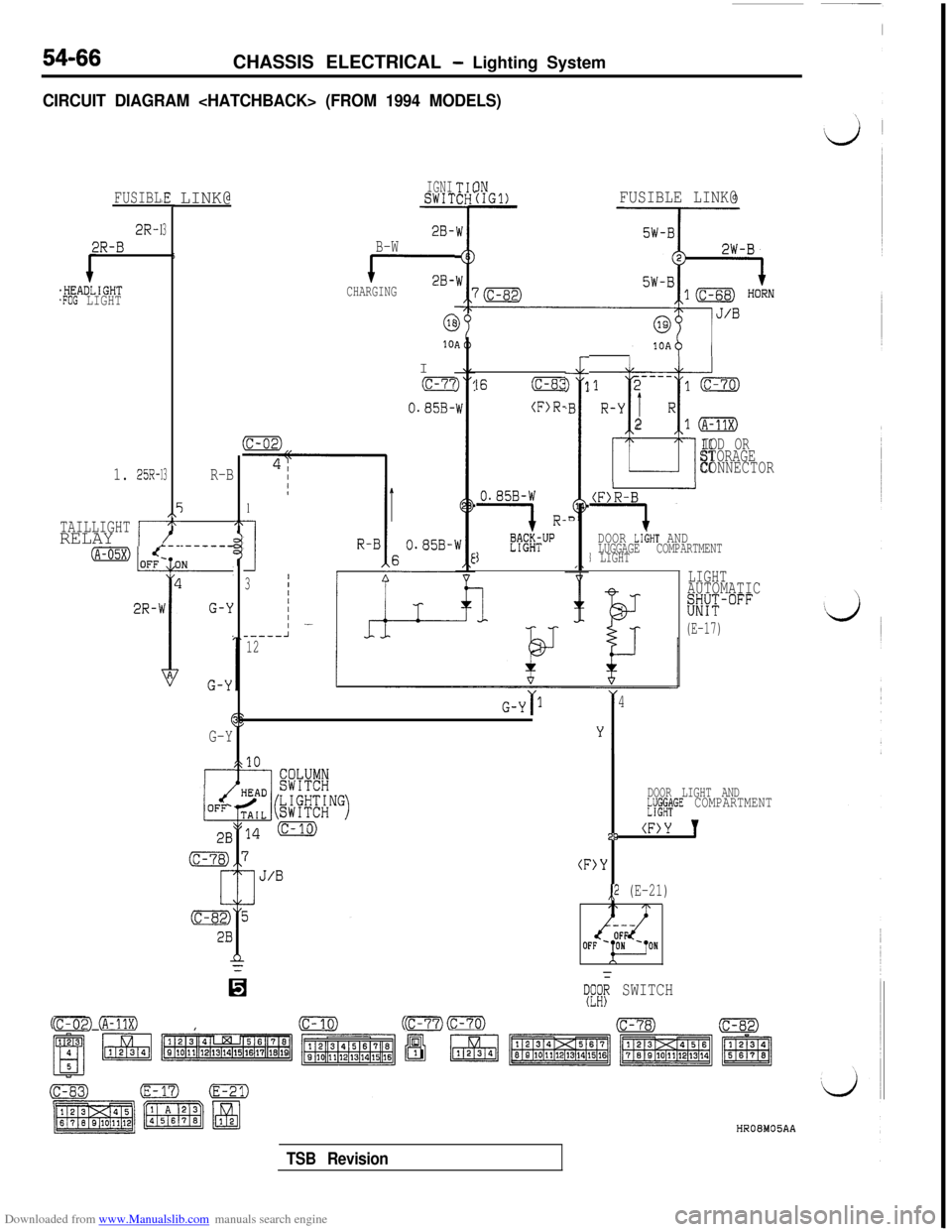
CIRCUIT DIAGRAM
FUSIBL
2R-1
2R-B
.HEADLIGHT.FOG LIGHT
#E
3
5
3
EI\-x-
1. 25R-1
TAILLIGHTRELAY ,r
LINK@
R-B
j2T
DOOR LIGHT AND.--__--LUGGAGE COMPARTMENT1 LIGHT
LIGHT
AUTOMATICKK-"""
-(E-17)
1
I
3
_----12
0.85B-W
1 R-
K#TUP1
(F>R-B
i-
G-Y ‘I4
&r1
G-Y
IDOOR LIGHT AND~JJ$C&GE COMPARTMENT29
(F>Y 'I
(F>Y
,,2 (E-21)
IGNISWIT
2B-B-W
cCHARGING
6I10
(c-7'i
O.S5B-
IN(IGl)FUSIBLE LINK@
07:;; SWITCH
cFE0 (A-11X)(c-02)(c-10)(c-68)cm~07)HROEMOBAA
16(c-8:!
(F>R-
----121mR-Y
1 R
t
210
IOD ORSTORAGE
CONNECTOR
TSB Revision
Page 566 of 738
Downloaded from www.Manualslib.com manuals search engine 54-70CHASSIS ELECTRICAL - Lighting System
OPERATION
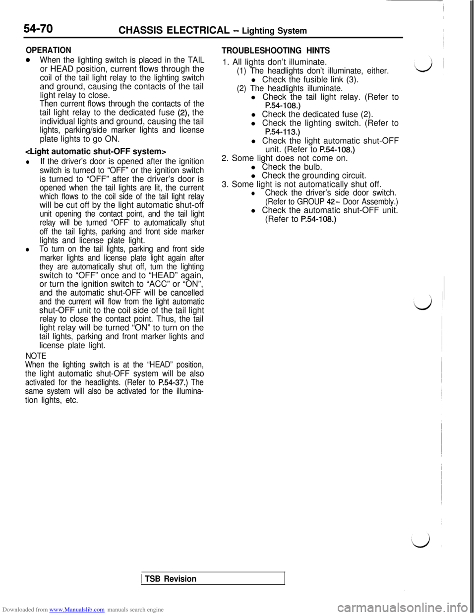
0When the lighting switch is placed in the TAILor HEAD position, current flows through the
coil of the tail light relay to the lighting switchand ground, causing the contacts of the tail
light relay to close.
Then current flows through the contacts of thetail light relay to the dedicated fuse
(2) the
individual lights and ground, causing the tail
lights, parking/side marker lights and licenseplate lights to go ON.
lIf the driver’s door is opened after the ignition
switch is turned to “OFF” or the ignition switchis turned to “OFF” after the driver’s door is
opened when the tail lights are lit, the current
which flows to the coil side of the tail light relaywill be cut off by the light automatic shut-off
unit opening the contact point, and the tail light
relay will be turned “OFF’ to automatically shut
off the tail lights, parking and front side marker
lights and license plate light.
lTo turn on the tail lights, parking and front side
marker lights and license plate light again after
they are automatically shut off, turn the lightingswitch to “OFF” once and to “HEAD” again,
or turn the ignition switch to “ACC” or “ON”,
and the automatic shut-OFF will be cancelled
and the current will flow from the light automaticshut-OFF unit to the coil side of the tail light
relay to close the contact point. Thus, the taillight relay will be turned “ON” to turn on the
tail lights, parking and front marker lights and
license plate light.
NOTE
When the lighting switch is at the “HEAD” position,
the light automatic shut-OFF system will be also
activated for the headlights. (Refer to P.54-37.) The
same system will also be activated for the illumina-
tion lights, etc.
TROUBLESHOOTING HINTS1. All lights don’t illuminate.
(1) The headlights don’t illuminate, either.l Check the fusible link (3).
(2) The headlights illuminate.l Check the tail light relay. (Refer to
P.54-108.)l Check the dedicated fuse (2).
l Check the lighting switch. (Refer to
P.54-113.)l Check the light automatic shut-OFF
unit. (Refer to
P.54-108.)2. Some light does not come on.
l Check the bulb.
l Check the grounding circuit.
3. Some light is not automatically shut off.
lCheck the driver’s side door switch.
(Refer to GROUP 42- Door Assembly.)l Check the automatic shut-OFF unit.
(Refer to
P.54-108.)
1 TSB Revision
Page 579 of 738
Downloaded from www.Manualslib.com manuals search engine CHASSIS ELECTRICAL - Lighting System54-83
L-i
OPERATIONl
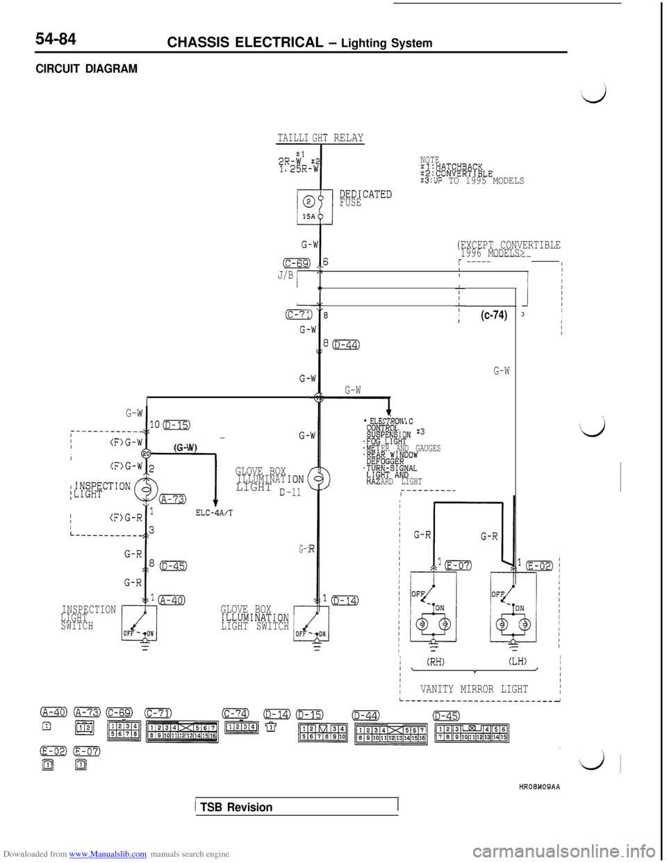
Battery voltage is always applied (via sub-fusiblelink No. (6) and multipurpose fuse No. (19))
to the luggage compartment light and door light.l
When the door is opened, the door switch is
switched ON and the door light illuminates.l When the
liftgate is opened, the luggage
compartment light switch is switched ON and
the luggage compartment light illuminates.GLOVE BOX LIGHT, VANITY MIRROR LIGHT AND INSPECTION LIGHT
OPERATIONl
When the lighting switch is.placed in the TAIL
or HEAD position, and the contacts of the tail
light relay close, battery voltage is applied viathe dedicated fuse (2) to the glove box light,
the vanity mirror light and the inspection light.l
When the glove box is opened, the glove box
illumination light switch is switched ON and the
glove box illumination light illuminates.l
When the vanity mirror lid is opened, the vanity
mirror light switch is switched ON and the vanity
mirror light illuminates.l
When the engine hood is opened, the inspection
light switch is switched ON and the inspection
light illuminates.
NOTE
The light automatic shut-off system is valid for theglove box light, vanity mirror light and inspection
light. (Refer to
P.54-37.)
i
TSB Revision
Page 580 of 738
Downloaded from www.Manualslib.com manuals search engine 54-84
CIRCUIT DIAGRAMCHASSIS ELECTRICAL
- Lighting System
TAILLIGH:T RELAY
:I2R-W1.25R-NOTEZ'l:HATCHBACK:2:CONVERTIBLE:3:UP TO 1995 MODELS
FUSE
I DED1CATED
(EXCEPT CONVERTIBLE1996 MODELS>
sr ------------_____IIIIII
G-
(c-69)
J/Br
J
IIIII1II/II
LIILIII&
G-
8(c-74)
G-WG-
G-W
I
G-W
100__-----_____/II(F)G-W-
IIt20(G-W)
G-
. ELEPiDnhll P
ga
:&
‘#
‘ZYEHA2
“II\VIY,”TROLyyu&N 3
ER AND GAUGES~;G;v#low
$Sa#AL
/ARD LIGHT---------_I
GLOVE BOXILLUMINATLIGHT o
ELC-4A/T
ION(
-11III
I1IL
G-i
-=
INSPECTION
LIGHT
SWITCHGLOVE BOXILLUMINATiON
LIGHT SWITCH
1I/(RH)(LH)II \///IIII/IVANITY MIRROR LIGHTI
HROMOQAA
1 TSB Revision
Page 585 of 738
Downloaded from www.Manualslib.com manuals search engine 1. When operation is normal
l
When the ignition switch is switched to the
ON position, battery voltage is applied (viathe multipurpose fuse (11) and hazard
switch) to the turn-signal and hazard flasher
unit.l
When the turn-signal switch is switched to
the LH position,
Trl (within the flasher unit)
is switched ON and OFF repeatedly.
Then the contacts of the relay 1 (also within
the flasher unit) repeatedly switch from ON
to OFF, causing the turn-signal lights and
turn-signal indicator light LH to flash.l
When the turn-signal switch is switched to
the RH position, Tr2 (within the flasher unit)
is switched ON and OFF repeatedly.Then the contacts of relay 2 (also within
the flasher unit) repeatedly switch from ON
to OFF, causing the turn-signal lights and
turn-signal indicator light RH to flash.2. If one of the bulbs is burned out
lIf the LH (or RH) turn-signal light bulb is
burned-out, the resistance of the turn-signalcircuit as a whole increases, resulting in
Lshorter ON and OFF intervals of the LHTrl (or RH Tr2) and a higher flashing rateof the LH lights (or RH lights).CHASSIS ELECTRICAL
- Lighting System54-89
TURN-SIGNAL LIGHT AND HAZARD
L
LIGHT
OPERATION
ed to the “ON” position, the relay contactof the turn signal and hazard flasher unit
is switched ON and OFF repeatedly, in thesame manner as for the operation of the
turn-signal lights, and the left and right turn-
signal lights and turn-signal indicator lights
simultaneously flash repeatedly.
NOTE
(1) The number of flashes of the hazard-warn-
ing lights does not change if there is dam-
aged or disconnected wiring of one light.
(2)The light automatic shut-OFF system is valid
for the illumination light of the hazard switch.(Refer to
P.54-37.)
TROUBLESHOOTING HINTS
1.The turn-signal lights and hazard-warning lightsdo not operate at all.
l Check the hazard switch contact (power
supply side).l Check the turn-signal and hazard flasher
unit.2. All turn-signal lights at the left (or right) side
do not function.
(1) The hazard-warning lights function normal-
ly-lCheck the hazard switch contact (turn-
signal side).l Check the turn-signal switch.
3.The number of flashes of the turn-signal lights
is excessive.l Check the bulbs.
4. The hazard-warning lights do not function.
(1) The turn-signal lights function normally.l
Check the hazard switch contact (haz-
ard-warning light side).
NOTE
For the troubleshooting hints of the automatic lightshut-OFF system, refer to
P.54-37.
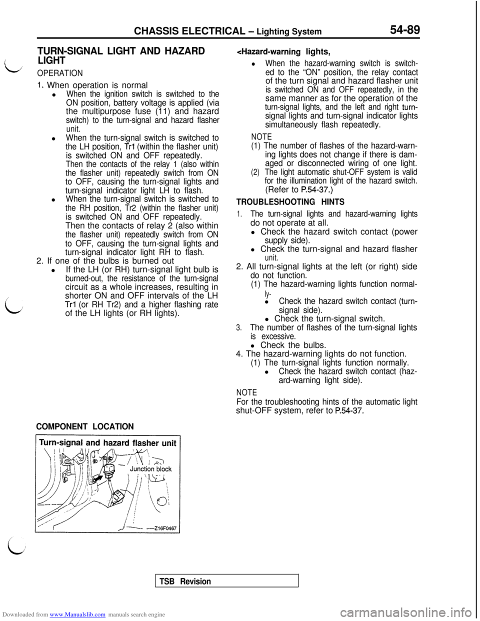
COMPONENT LOCATION
TSB Revision
Page 604 of 738
Downloaded from www.Manualslib.com manuals search engine 54-108
CHASSIS ELECTRICAL - Lighting System
1 ‘-‘FE%!oooou2394
Y18AOO61
RELAY
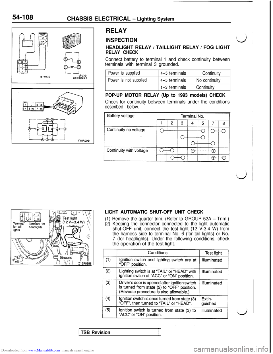
INSPECTIONHEADLIGHT RELAY
/ TAILLIGHT RELAY / FOG LIGHT
RELAY CHECK
Connect battery to terminal 1 and check continuity between
terminals with terminal 3 grounded.
Power is supplied4-5 terminals
Continuity
Power is not supplied4-5 terminalsNo continuity
1-3 terminals
Continuity
POP-UP MOTOR RELAY (Up to 1993 models) CHECK
Check for continuity between terminals under the conditions
described below.
LIGHT AUTOMATIC SHUT-OFF UNIT CHECK
(1) Remove the quarter trim. (Refer to GROUP 52A - Trim.)
(2) Keeping the connector connected to the light automatic
shut-OFF unit, connect the test light (12 V-3.4 W) from
the harness side to terminal No. 6 (for tail lights) or No.
7 (for headlights). Under the following conditions, checkthe operation of the test light.
id
/ TSB Revision
Page 611 of 738
Downloaded from www.Manualslib.com manuals search engine CHASSIS ELECTRICAL - Horn54-115
HORN
SPECIFICATIONS
GENERAL SPECIFICATIONS
Horn (Except for theft-alarm horn)
ItemsI Specifications
Type
Effective sounding voltage V
Power consumption A
Sound level dB
Fundamental frequency Hz
“low” sound
“high” sound
“low” sound
“high” sound
Fiat type
11.5-15
3.0
100-112
100-112350-390395-435
Theft-alarm horn
1 ItemsI Specifications
1 Type1 Flat typeI
Effective sounding voltage V
Power consumption A
Sound level dB
Fundamental frequency Hz
11-14.5
Max. 3.5
105-120I
I 405-435
TROUBLESHOOTING
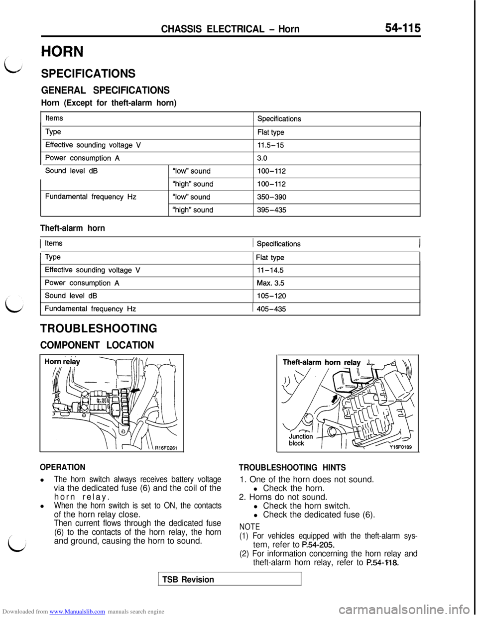
COMPONENT LOCATION
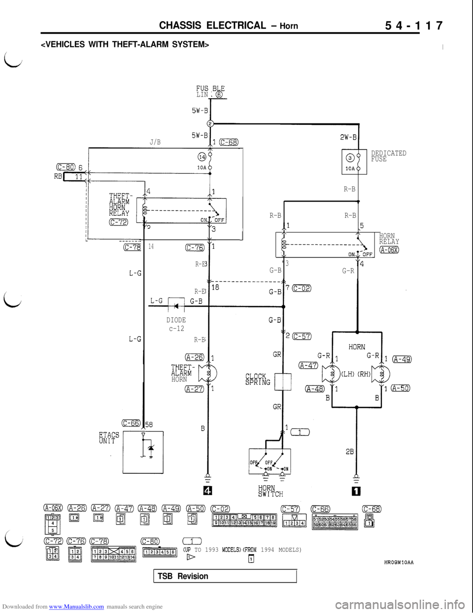
OPERATIONl
The horn switch always receives battery voltagevia the dedicated fuse (6) and the coil of the
horn relay.
l
When the horn switch is set to ON, the contactsof the horn relay close.
Then current flows through the dedicated fuse
(6) to the contacts of the horn relay, the hornand ground, causing the horn to sound.1. One of the horn does not sound.
TROUBLESHOOTING HINTSl Check the horn.
2. Horns do not sound.
l Check the horn switch.
l Check the dedicated fuse (6).
NOTE
(1) For vehicles equipped with the theft-alarm sys-tem, refer to
P.54-205.
(2) For information concerning the horn relay and
theft-alarm horn relay, refer to
P.54-?18.
TSB Revision
Page 613 of 738
Downloaded from www.Manualslib.com manuals search engine CHASSIS ELECTRICAL - Horn54-117
i
FUSLIN
5W-B
5W-BJ/Bl(c-68)I
.BsEbL
I
L ------ -----_.
(C-7E
L-C
LKFr
14(c-76)
R-E
R-E
-=-FF
DIODE
c-12
R-B
;r;EKHORN
J
0DEDICATED
FUSE
10A
R-B
R-BR-B
,,l,5,\I\HORN
RELAY------___----____
\/ON,;-OFF(A-06X)
"3'4
G-B
G-R
(c-80) (1(UP TO 1993 MODELS)(FROM 1994 MODELS)
HROSMlOAA
TSB Revision
Page 614 of 738
Downloaded from www.Manualslib.com manuals search engine 54-I 18CHASSIS ELECTRICAL - HornHORN SWITCH
REMOVAL AND INSTALLATION(UP TO 1993 MODELS)
~
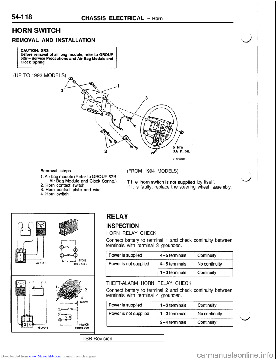
Y16FO207Removal steps
1. Air bag module (Refer to GROUP 528
(FROM 1994 MODELS)
- Air Bag Module and Clock Spring.)2. Horn contact switch3. Horn contact plate and wire4. Horn switchThe
horn switch is not supplied
If it is faulty, replace the steeringby itself.wheel assembly.i-.
-L 16FOO61200002400
RELAY
INSPECTION
HORN RELAY CHECK
Connect battery to terminal 1 and check continuity between
terminals with terminal 3 grounded.
~1
THEFT-ALARM HORN RELAY CHECK
Connect battery to terminal 2 and check continuity between
terminals with terminal 4 grounded.TSB Revision