MITSUBISHI 3000GT 1992 2.G Workshop Manual
Manufacturer: MITSUBISHI, Model Year: 1992, Model line: 3000GT, Model: MITSUBISHI 3000GT 1992 2.GPages: 738, PDF Size: 35.06 MB
Page 461 of 738
Downloaded from www.Manualslib.com manuals search engine ENGINE ELECTRICAL - Charging System16-15
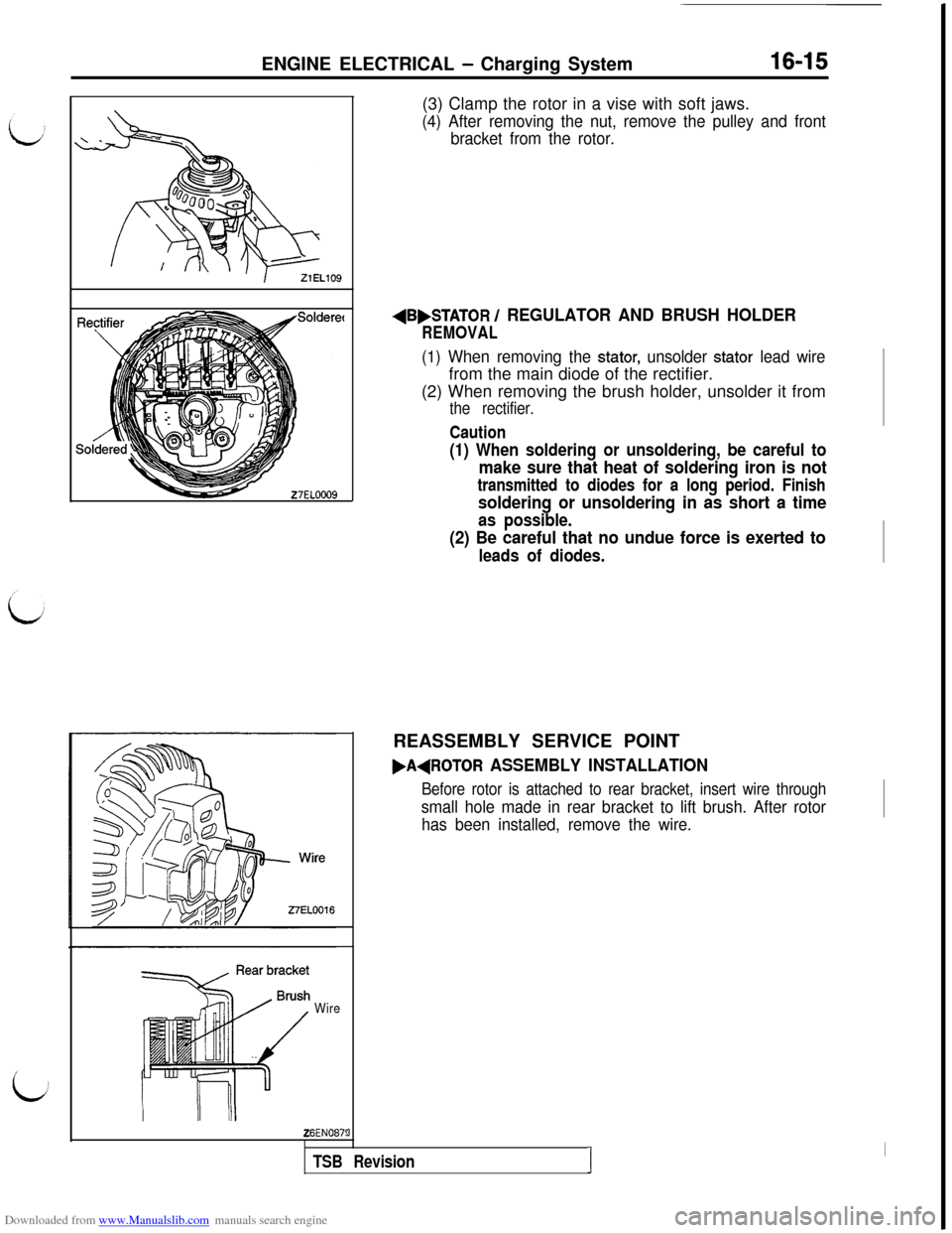
WireZ6EN087!(3) Clamp the rotor in a vise with soft jaws.
(4) After removing the nut, remove the pulley and front
bracket from the rotor.
AB,STATOR / REGULATOR AND BRUSH HOLDER
REMOVAL
(1) When removing the stator, unsolder stator lead wirefrom the main diode of the rectifier.
(2) When removing the brush holder, unsolder it from
the rectifier.
Caution
(1) When soldering or unsoldering, be careful to
make sure that heat of soldering iron is not
transmitted to diodes for a long period. Finish
soldering or unsoldering in as short a time
as possible.
(2) Be careful that no undue force is exerted to
leads of diodes.REASSEMBLY SERVICE POINT
FAdROTOR ASSEMBLY INSTALLATION
Before rotor is attached to rear bracket, insert wire through
small hole made in rear bracket to lift brush. After rotor
has been installed, remove the wire.
3
TSB RevisionI
I
Page 462 of 738
Downloaded from www.Manualslib.com manuals search engine ENGINE ELECTRICAL - Charging System
h\Z3ELOlO
\23ELOllINSPECTION
ROTOR
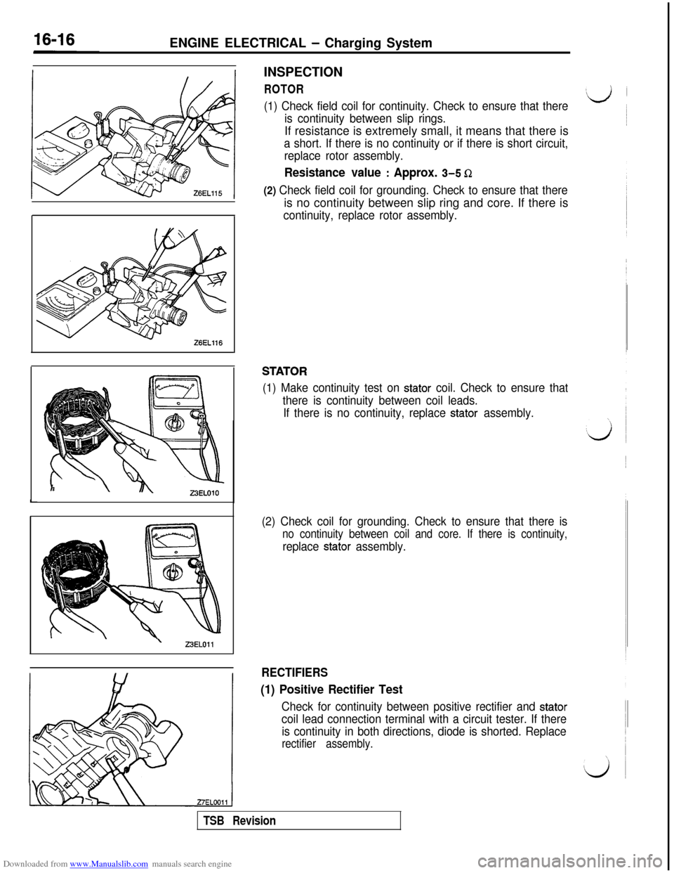
(1) Check field coil for continuity. Check to ensure that there
is continuity between slip rings.If resistance is extremely small, it means that there is
a short. If there is no continuity or if there is short circuit,
replace rotor assembly.
Resistance value : Approx. 3-5 Q
(2) Check field coil for grounding. Check to ensure that thereis no continuity between slip ring and core. If there is
continuity, replace rotor assembly.
STATOR
(1) Make continuity test on stator coil. Check to ensure that
there is continuity between coil leads.
If there is no continuity, replace
stator assembly.
(2) Check coil for grounding. Check to ensure that there is
no continuity between coil and core. If there is continuity,
replace stator assembly.
RECTIFIERS
(1) Positive Rectifier Test
Check for continuity between positive rectifier and stator
coil lead connection terminal with a circuit tester. If there
is continuity in both directions, diode is shorted. Replace
rectifier assembly.
TSB Revision
Page 463 of 738
Downloaded from www.Manualslib.com manuals search engine ENGINE ELECTRICAL - Charging System16-17
Limit line
WELO
,Soldered
27EL0014
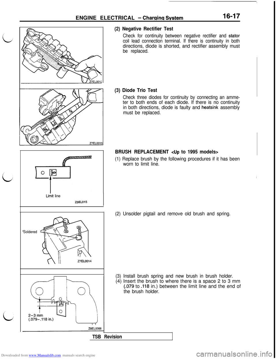
(2) Negative Rectifier Test
Check for continuity between negative rectifier and stator
coil lead connection terminal. If there is continuity in both
directions, diode is shorted, and rectifier assembly must
be replaced.
(3) Diode Trio Test
Check three diodes for continuity by connecting an amme-
ter to both ends of each diode. If there is no continuity
in both directions, diode is faulty and
heatsink assembly
must be replaced.
BRUSH REPLACEMENT
(1) Replace brush by the following procedures if it has been
worn to limit line.
(2) Unsolder pigtail and remove old brush and spring.
(3) Install brush spring and new brush in brush holder.(4) Insert the brush to where there is a space 2 to 3 mm
(.079 to .118 in.) between the limit line and the end of
the brush holder.
TSB Revision
Page 464 of 738
Downloaded from www.Manualslib.com manuals search engine 16-18ENGINE ELECTRICAL - Charging System
Soldered
Limit line
&
mm
o L%4
-if
T
9EN0192
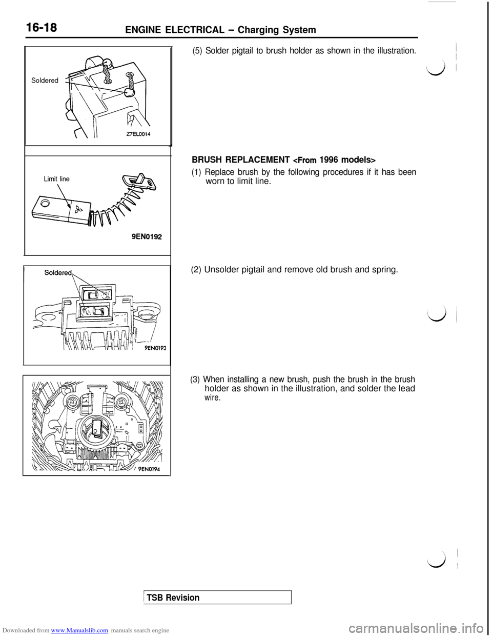
(5) Solder pigtail to brush holder as shown in the illustration.
BRUSH REPLACEMENT
(1) Replace brush by the following procedures if it has beenworn to limit line.
(2) Unsolder pigtail and remove old brush and spring.
(3) When installing a new brush, push the brush in the brushholder as shown in the illustration, and solder the lead
wire.
1 TSB Revision
Page 465 of 738
Downloaded from www.Manualslib.com manuals search engine ENGINE ELECTRICAL - Starting System16-19
L/J
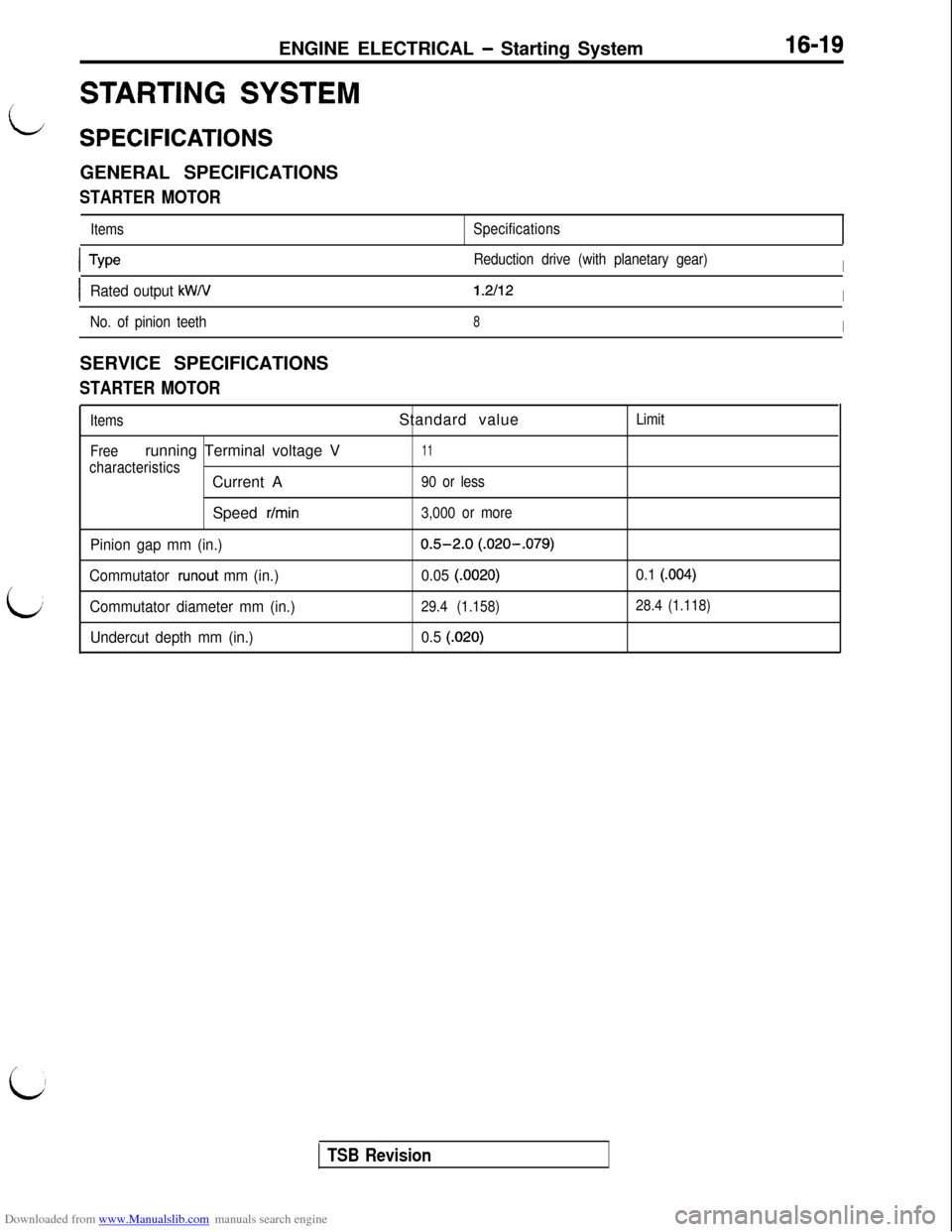
STARTING SYSTEM
SPECIFICATIONSGENERAL SPECIFICATIONS
STARTER MOTOR
ItemsSpecifications
L
ITypeReduction drive (with planetary gear)I
IRated output kW/V1.2112I
No. of pinion teeth8ISERVICE SPECIFICATIONS
STARTER MOTOR
Items
Freerunning Terminal voltage V
characteristicsCurrent A
Speed
r/min
Pinion gap mm (in.)
Commutator
runout mm (in.)
Commutator diameter mm (in.)
Undercut depth mm (in.)Standard value
11
90 or less
3,000 or more
0.5-2.0 (.020-.079)
0.05
(.0020)
29.4 (1.158)
0.5 (.020)Limit
0.1 (.004)
28.4 (1.118)
i
TSB Revision
Page 466 of 738
Downloaded from www.Manualslib.com manuals search engine 16-20ENGINE ELECTRICAL - Starting SystemTROUBLESHOOTING
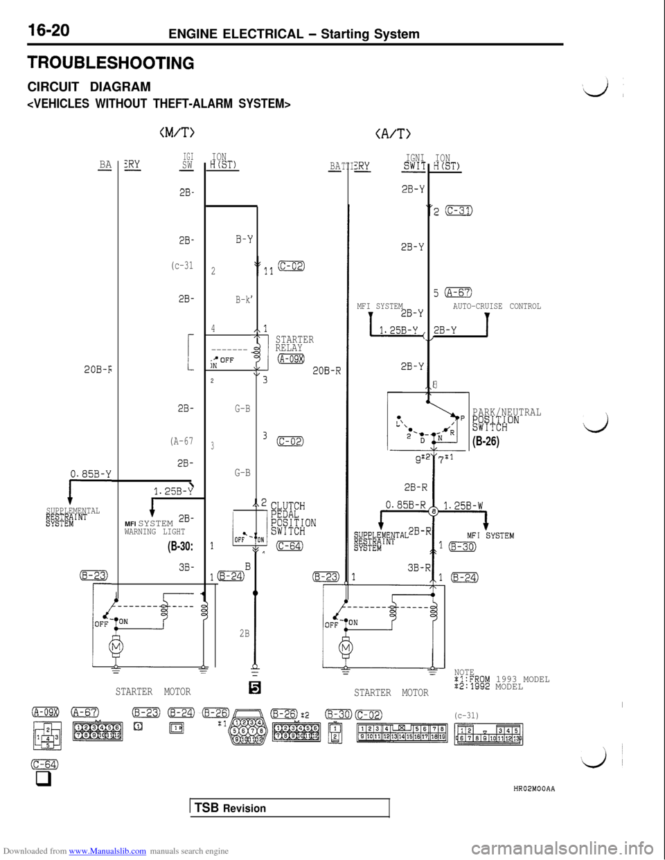
CIRCUIT DIAGRAM
(M/T>(A/T>
IGISW-
2B-
2B-
(c-31
2B-
!
2B-
(A-67
2B-ION
HCST)IGNIZRYSWIT-
2B-Y
IONHCST)BAZRY--BA-TTI
B-1
2
B-k
4
-------;;OFF2
G-B
3
G-B
I
I
/\17rSTARTERRELAY
(A-09X)AL\I;20B-R
3.
,.;
,
8$J (c-64)
0I
2B-Y
5(A-67)
AUTO-CRUISE CONTROL
2B-Y 1
MFI SYSTEM
1 1.25y
2B-Y20B-F
3
PARK/NEUTRAL&~#ONij
(B-26)
g:27:1
i28-R
0.85B-Y
ISUPPLEMENTALgf;EEiINT
1.25B-y\
1MFI SYSTEM 2B-WARNING LIGHT
1iOF?-
lmB
2B
(B-30:
3B-(8-23)
rii------- ____
d
0
==
STARTER MOTOR
NOTE%l:FROM 1993 MODEL%2:1992 MODEL
I(c-31)
STARTER MOTOR
(c-64)q
HR02MOOAA
1 TSB Revision
Page 467 of 738
Downloaded from www.Manualslib.com manuals search engine ENGINE ELECTRICAL - Starting System16-21
FUSIBLE LINK@
zJ==%~,
IGNITION
2B-k
iWITCH
B-L
B-l
2
B-j
4
2B-k1
(c-31:
2B-kJ/Br
rwER
(A-OSXII-
----------SrOFFON
2
G-B
(c-02
3
G-E
PEDAL&~#,;~ONB
28-k
IOD ORSTORAGE
CONNECTOR0.85B-Y
R-B
1 I------. BUZZER. MFI SYSTEM.DOME#T,. fl@+NG
LIGHT
AND IGNITION KEY
CYLINDER
ILLUMINATION LIGHT
2G-3130.85R-B
1E;$gAb;GHT AND
EW';RTMENT
i
R-B2B-Y
3B-F
20B-R
WHEN
KEY IS
REMOVED (B-23:
r-
'TE
!
LG-B
21Q
MOTOR
B-l
B-L-
*;~F$K& DOOR
.ACTWE AEROB-l
4EHE;iALARM
(c-65)
r
d
6
I
ms
(c-31)(c-56) (c-58)(c-64)
STARTER
mf3t7)(c-02)
HR02MOlAA
1 TSB Revision
Page 468 of 738
Downloaded from www.Manualslib.com manuals search engine 16-22ENGINE ELECTRICAL - Starting System
#d ~
FUSIBLE LINK@IGNITIONf
T2B-k
(c-31:
1
iWITCH (ST)
.----11 1II
I1
I
1 1
3 /3
I.----A 2
2B-Y
B-Y
4ISTARTER
RELAY
@liB
MFI SYSTEM2B-Y
--____----------------.-*OFFON
2
G-B
IOD OR
STORAGE
CONNECTOR32B~yg$!y”IsE (c-02:
O.a5R-BR-B2B-Y
eQsCIAk;GHT AND
COMPARTMENT
LIGHT
3
'BUZZERPARK/
. f~[f,\6[!?.+~~ [#~f#hI
CYLINDER
ILLUMINATION
tIGHT(B-26)
L’\2'D-'
9:2
r’”
,:1R-i
NOTEXl FROM 1993 MODEL:2 1992 MODEL
'l.25B-W
MFI SYSTEM
2B-R
BATTERY(
2B-R
208-R(B-30)
3B-R
(B-23)1(B-24)
SUPPLEMENTAL
1gEyL&E"i I NT
h
STARTER ~0~0: WHEN
KEY IS
REMOVED
B-1
B-L
$FRIW& DOOR
.ACTIVE AEROB-I
*TWF;~ALARM
HR02M02AA
1 TSB Revision
Page 469 of 738
Downloaded from www.Manualslib.com manuals search engine ENGINE ELECTRICAL - Starting System16-23
OPERATION
L
0For models equipped with the M/T, the clutch
pedal position switch contact is switched OFF
when the clutch pedal is depressed; when the
ignition switch is then switched to the “ST’ posi-tion, electricity flows to the starter relay and
the starter motor, the contact (magnetic switch)of the starter is switched ON and the starter
motor is activated.
NOTEIf the ignition switch is switched to the “ST
position without the clutch pedal being de-
pressed, electricity flows to the starter relay
(coil), the clutch pedal position switch (contacts)
and to ground, with the result that the contacts
of the starter relay are switched OFF, and, be-
cause the power to the starter motor is thereby
interrupted, the starter motor is not activated.lFor models equipped with the
AIT, when the
ignition switch is switched to the “ST’ position
while the selector lever is at the “P” or “N” posi-
tion, the contact (magnetic switch) of the starter
is switched ON and the starter motor is activated.
TROUBLESHOOTING HINTSThe starter motor does not operate at all.
l Check the starter (coil).
lCheck for poor contact at the battery terminals
and starter.l Check Park/Neutral position switch.
l Check clutch pedal position switch.
l Check starter relay.
l Check theft-alarm starter relay.
l Check key reminder switch.
i
/’
L&J
Fieldcoil wire
Iii?Stopper
IPinion gap
PinionZ6EL003
STARTER MOTORREMOVAL AND INSTALLATION
Refer to GROUP 22
- Manual Transaxle, or GROUP 23 -
Automatic Transaxle.INSPECTION
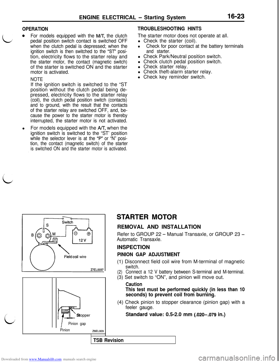
PINION GAP ADJUSTMENT(1) Disconnect field coil wire from M-terminal of magnetic
switch.
(2)Connect a 12 V battery between S-terminal and M-terminal.(3) Set switch to “ON”, and pinion will move out.
Caution
This test must be performed quickly (in less than 10
seconds) to prevent coil from burning.(4) Check pinion to stopper clearance (pinion gap) with a
feeler gauge.
Standard value: 0.5-2.0 mm (.020-,079 in.)
TSB Revision
Page 470 of 738
Downloaded from www.Manualslib.com manuals search engine 16-24ENGINE ELECTRICAL - Starting System
ZlEL11327ELOOlQ
0
5
Startermotor
Carbon-pile rheostat
-I-Battery
i12v I
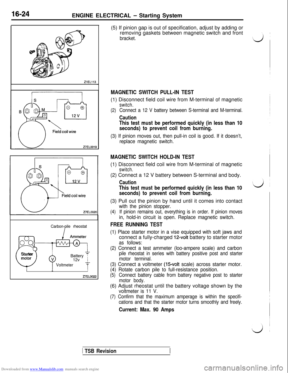
Voltmeter7-II27ELOO22(5) If pinion gap is out of specification, adjust by adding or
removing gaskets between magnetic switch and front
bracket.
MAGNETIC SWITCH PULL-IN TEST(1) Disconnect field coil wire from M-terminal of magnetic
switch.
(2)
Connect a 12 V battery between S-terminal and M-terminal.
Caution
This test must be performed quickly (in less than 10
seconds) to prevent coil from burning.
(3) If pinion moves out, then pull-in coil is good. If it doesn’t,
replace magnetic switch.
MAGNETIC SWITCH HOLD-IN TEST(1) Disconnect field coil wire from M-terminal of magnetic
switch.(2) Connect a 12 V battery between S-terminal and body.
Caution
This test must be performed quickly (in less than 10
seconds) to prevent coil from burning.(3) Pull out the pinion by hand until it comes into contact
with the pinion stopper.
(4)If pinion remains out, everything is in order. If pinion moves
in, hold-in circuit is open. Replace magnetic switch.
FREE RUNNING TEST
(1) Place starter motor in a vise equipped with soft jaws andconnect a fully-charged
12-volt battery to starter motor
as follows:
(2) Connect a test ammeter (loo-ampere scale) and carbon
pile rheostat in series with battery positive post and starter
motor terminal.
(3) Connect a voltmeter (15volt scale) across starter motor.
(4) Rotate carbon pile to full-resistance position.
(5)Connect battery cable from battery negative post to starter
motor body.(6) Adjust rheostat until the battery voltage shown by the
voltmeter is 11 V.
(7) Confirm that the maximum amperage is within the specifi-
cations and that the starter motor turns smoothly and freely.
Current: Max. 90 Amps
1 TSB Revision