MITSUBISHI 3000GT 1992 2.G Workshop Manual
Manufacturer: MITSUBISHI, Model Year: 1992, Model line: 3000GT, Model: MITSUBISHI 3000GT 1992 2.GPages: 738, PDF Size: 35.06 MB
Page 481 of 738

Downloaded from www.Manualslib.com manuals search engine i;ENGINE ELECTRICAL
- Ignition System16-35
OPERATIONl
Turn ignition switch to .“ON”position, and batteryvoltage will be applied to primary winding of
ignition coil.l
When crankshaft position sensor and camshaft
position sensor signal is input to engine control
module, engine control module makes ON-OFF
control of power transistors one by one.l When power transistor is turned on, current
flows from ignition coil (primary winding) to
ground through power transistor.l When power transistor A is turned from ON
to OFF, the spark plugs of No. 1 and No. 4
cylinders spark. Turning of power transistor B
from ON to OFF will produce sparking in spark
plugs of No. 2 and No. 5 cylinders. Furthermore,
when power transistor C is turned from ON toOFF, sparking is produced in spark plugs of
No. 3 and No. 6 cylinders.
TROUBLESHOOTING HINTS1. Engine cranks, but does not start.
(1) Spark is insufficient or does not occur at
all (on spark plug).l Check ignition coil.
l Check camshaft position sensor and
crankshaft position sensorl Check power transistor.
l Check spark plugs.
l Check spark plug cable.
(2) Spark is good.
l Check ignition timing.
2. Engine idles roughly or stalls.
l Check spark plugs.
l Check ignition timing.
l Check ignition coil.
l Check spark plug cable.
3. Poor acceleration
l Check ignition timing.
l Check spark plug cable.
l Check ignition coil.
TSB Revision
Page 482 of 738
Downloaded from www.Manualslib.com manuals search engine 16-36ENGINE ELECTRICAL - Ignition System
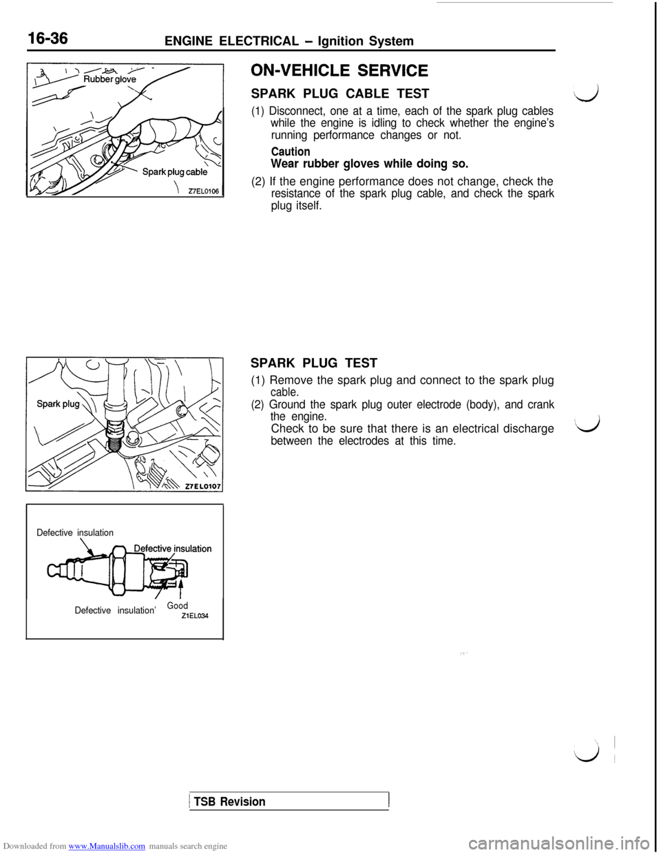
Defective insulation
Defective insulation’
GoodZiELO34
ON-VEHICLE SERVICESPARK PLUG CABLE TEST
,d
(1) Disconnect, one at a time, each of the spark plug cables
while the engine is idling to check whether the engine’s
running performance changes or not.
Caution
Wear rubber gloves while doing so.(2) If the engine performance does not change, check the
resistance of the spark plug cable, and check the spark
plug itself.SPARK PLUG TEST
(1) Remove the spark plug and connect to the spark plug
cable.
(2) Ground the spark plug outer electrode (body), and crank
the engine.Check to be sure that there is an electrical discharge
between the electrodes at this time.
‘d
1 TSB Revision
Page 483 of 738
Downloaded from www.Manualslib.com manuals search engine /
LiENGINE ELECTRICAL
- lanition Svstem16-37
--7EL0134IGNITION SECONDARY VOLTAGE WAVE-FORM
CHECK
MEASUREMENT METHOD
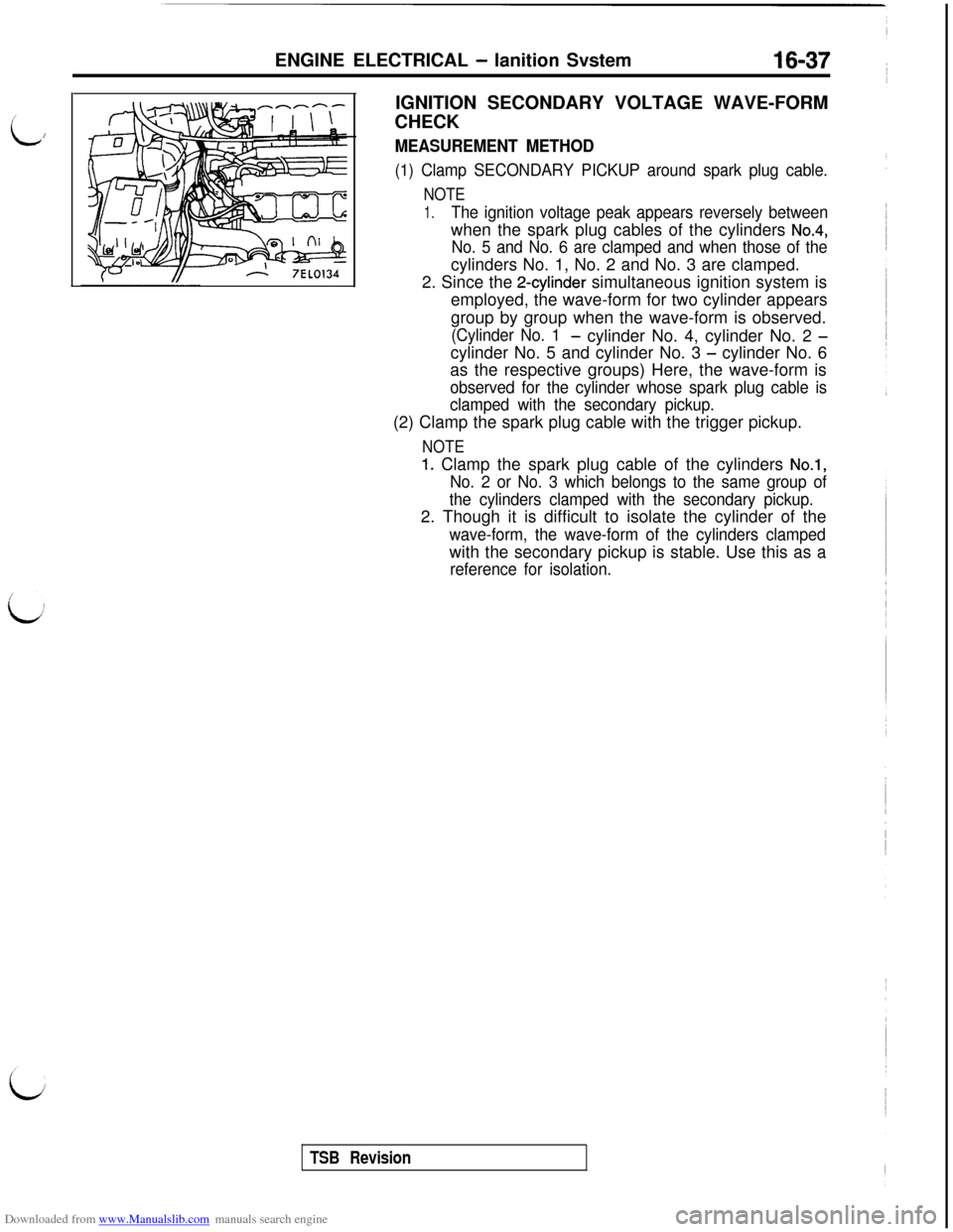
(1) Clamp SECONDARY PICKUP around spark plug cable.
NOTE
1.The ignition voltage peak appears reversely betweenwhen the spark plug cables of the cylinders
No.4,
No. 5 and No. 6 are clamped and when those of thecylinders No. 1, No. 2 and No. 3 are clamped.
2. Since the
2-cylinder simultaneous ignition system is
employed, the wave-form for two cylinder appears
group by group when the wave-form is observed.
(Cylinder No. 1- cylinder No. 4, cylinder No. 2 -cylinder No. 5 and cylinder No. 3
- cylinder No. 6
as the respective groups) Here, the wave-form is
observed for the cylinder whose spark plug cable is
clamped with the secondary pickup.(2) Clamp the spark plug cable with the trigger pickup.
NOTE
1. Clamp the spark plug cable of the cylinders No.1,
No. 2 or No. 3 which belongs to the same group of
the cylinders clamped with the secondary pickup.2. Though it is difficult to isolate the cylinder of the
wave-form, the wave-form of the cylinders clampedwith the secondary pickup is stable. Use this as a
reference for isolation.
TSB Revision
Page 484 of 738
Downloaded from www.Manualslib.com manuals search engine 16-38ENGINE ELECTRICAL - Ignition System
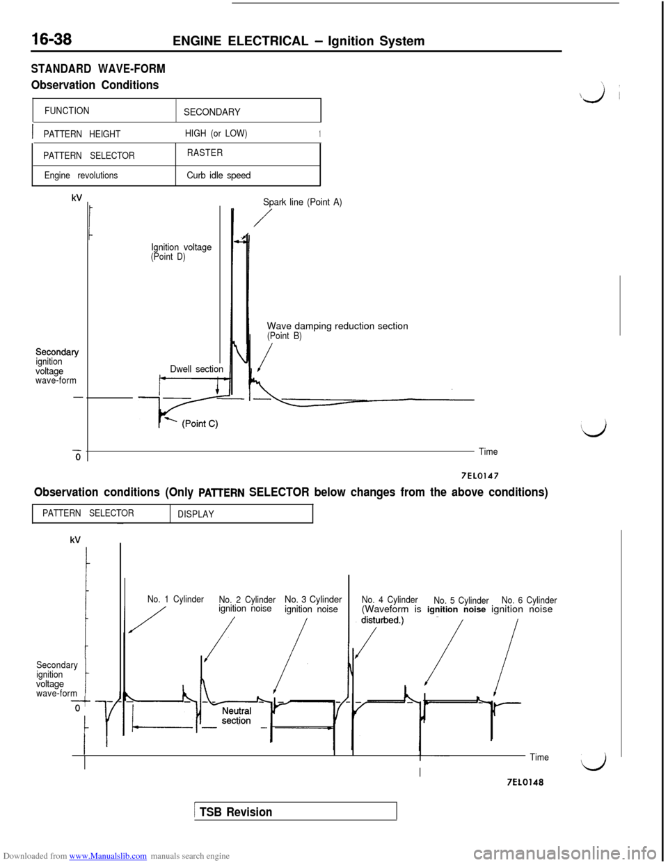
STANDARD WAVE-FORM
Observation Conditions
FUNCTIONSECONDARY
\
\j’i
IPATTERN HEIGHTHIGH (or LOW)1
PATTERN SELECTORRASTER
Engine revolutions
Curb idle speed
kV
Secondary
ignition
voltagewave-form
-6
Ignition voltage(Point D)
Dwell sectionSpark line (Point A)
/Wave damping reduction section
(Point B)
/
Time
7EL0147
Observation conditions (Only PAlTERN SELECTOR below changes from the above conditions)
PATTERN SELECTOR
DISPLAY
Secondary
ignition
voltagewave-formt
No. 1 Cylinder
No. 2 Cylinderignition noiseNo. 3 Cylinder
ignition noiseNo. 4 Cylinder
No. 5 CylinderNo. 6 Cylinder(Waveform is ignition noise ignition noise
TimeI)I7EL0148
1 TSB Revision
Page 485 of 738
Downloaded from www.Manualslib.com manuals search engine ENGINE ELECTRICAL - Ignition System16-39
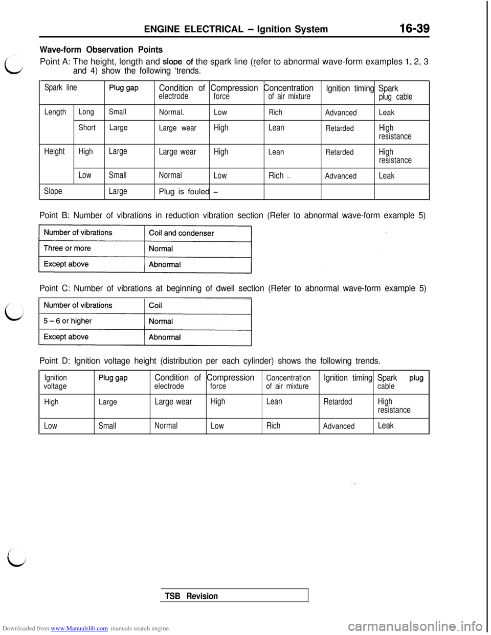
Wave-form Observation PointsPoint A: The height, length and
slope~of the spark line (refer to abnormal wave-form examples 1, 2, 3
and 4) show the following ‘trends.’\
Spark linePlug gapCondition of Compression Concentration
electrode
forceIgnition timing Sparkof air mixture
plug cable
LengthLongSmallNormal.
LowRichAdvancedLeak
ShortLarge
Large wear
HighLeanRetardedHigh
resistance
Height
HighLargeLarge wearHighLeanRetardedHigh
resistance
LowSmallNormal
Low
Rich _AdvancedLeak
SlopeLargePlug is fouled
-
Point B: Number of vibrations in reduction vibration section (Refer to abnormal wave-form example 5)
Point C: Number of vibrations at beginning of dwell section (Refer to abnormal wave-form example 5)
Point D: Ignition voltage height (distribution per each cylinder) shows the following trends.
Ignition
voltagePlug gapCondition of CompressionConcentration
electrodeIgnition timing Spark
forceof air mixtureplugcable
HighLarge
Large wearHighLean
RetardedHigh
resistance
LowSmallNormal
LowRich
AdvancedLeak
TSB Revision
Page 486 of 738
Downloaded from www.Manualslib.com manuals search engine 16-40ENGINE ELECTRICAL - Ignition System
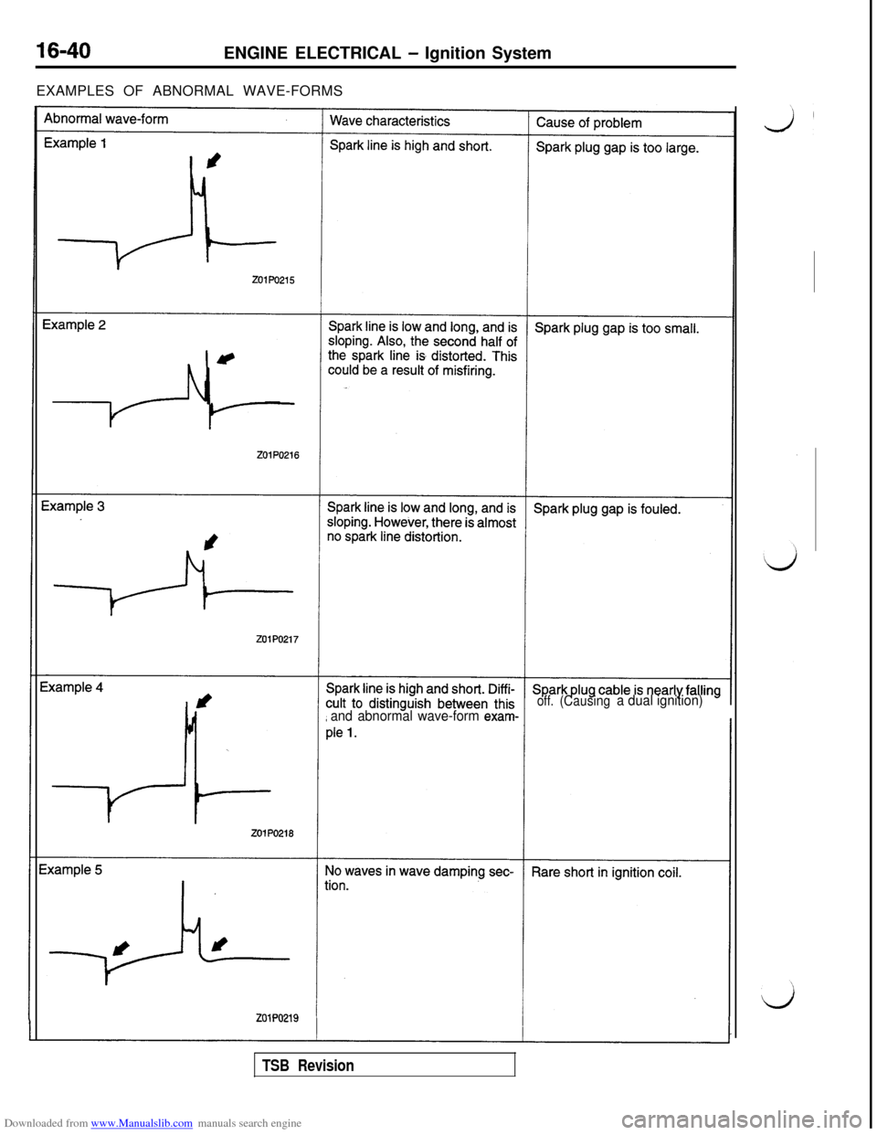
EXAMPLES OF ABNORMAL WAVE-FORMS
off.
and abnormal wave-form exam-
(Causinga dual ignition)
TSB Revision
Page 487 of 738
Downloaded from www.Manualslib.com manuals search engine ENGINE ELECTRICAL - lanition Svstem16-41
/
L
i
Analyzer
GroundL
01L1008
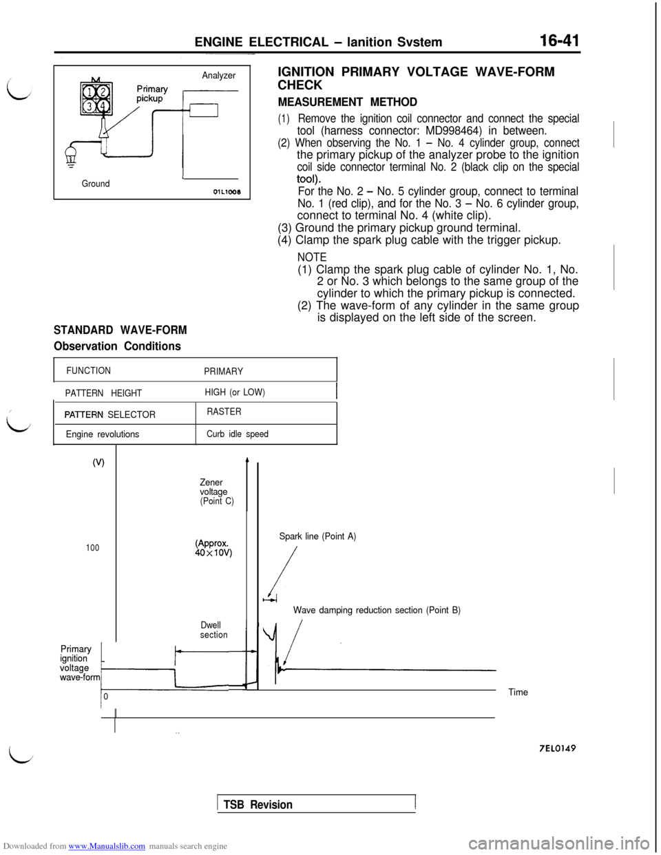
STANDARD WAVE-FORM
Observation ConditionsIGNITION PRIMARY VOLTAGE WAVE-FORM
CHECK
MEASUREMENT METHOD
(1)Remove the ignition coil connector and connect the special
tool (harness connector: MD998464) in between.
(2) When observing the No. 1 - No. 4 cylinder group, connectthe primary pickup of the analyzer probe to the ignition
coil side connector terminal No. 2 (black clip on the special
tool).
For the No. 2 - No. 5 cylinder group, connect to terminal
No. 1 (red clip), and for the No. 3
- No. 6 cylinder group,connect to terminal No. 4 (white clip).
(3) Ground the primary pickup ground terminal.
(4) Clamp the spark plug cable with the trigger pickup.
NOTE(1) Clamp the spark plug cable of cylinder No. 1, No.
2 or No. 3 which belongs to the same group of the
cylinder to which the primary pickup is connected.
(2) The wave-form of any cylinder in the same group
is displayed on the left side of the screen.
FUNCTION
PRIMARY
PATTERN HEIGHTHIGH (or LOW)
PAVERN SELECTOR
Engine revolutionsRASTER
Curb idle speed
(V)
100
Primary Primary*ignition ignition
voltage voltage
wave-form
owave-formkr
0
Zener
voltage
(Point C)
Dwell
section
b
Spark line (Point A)
/b-4
Wave damping reduction section (Point B)
/
Time
7EL0149
/ TSB Revision
Page 488 of 738
Downloaded from www.Manualslib.com manuals search engine 16-42ENGINE ELECTRICAL - Ignition System
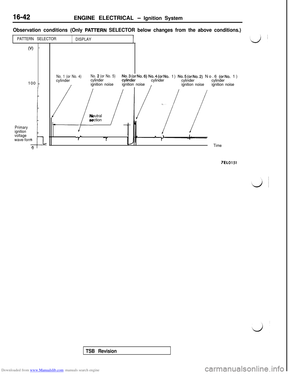
Observation conditions (Only PAlTERN SELECTOR below changes from the above conditions.)
PATTERN SELECTOR
DISPLAY1
(V) -100
-
Primary
ignition
voltage
i
wave-form
0No. 1 (or No. 4)
cylinderNo. 2 (or No. 5)cylinderNq.3(orNo.6) No.4(orNo. 1) No.5(orNo.2) No.6 (orNo. 1)
ignition noisecylinder
ignition noisecylinder
cylinder
ignition noisecylinder
/
I
/ignition noise
:./ /Neutral
section
/
Time
7EL0151
TSB Revision
Page 489 of 738

Downloaded from www.Manualslib.com manuals search engine ENGINE ELECTRICAL - Ignition System16-43
Wave-form Observation Points/
LPoint A: The height, length and slope of the spark line (refer to abnormal wave-form examples 1, 2, 3and 4) show the following trends.
Spark linePlug gapCondition of CompressionConcentra-Ignition timing High tension
electrodeforcetion of air mix-cable
tureLength Long
SmallNormalLowRichAdvanced
Leak
Short
LargeLarge wearHighLeanRetardedHigh
resistanceHeight High
LargeLarge wearHighLeanRetardedHigh
resistance
LowSmall
NormalLowRichAdvancedLeak
SlopeLargePlug is fouled-
Point B: Number of vibrations in reduction vibration section
(Refer to abnormal wave-form example 5)
Number of vibrationsCoil and condenser
I3 or higher/ Normal
Except aboveAbnormal
Point C: Height of Zener voltage
Height of Zener voltageProbable cause
HigherProblem in Zener diode
LowerAbnormal resistance in pri-
mary coil circuit
TSB Revision
Page 490 of 738
Downloaded from www.Manualslib.com manuals search engine ENGINE ELECTRICAL - Ignition System
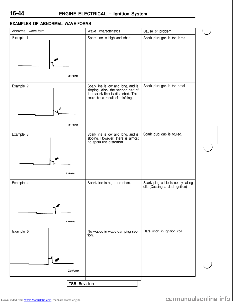
EXAMPLES OF ABNORMAL WAVE-FORMS
Abnormal wave-form
Wave characteristics
Cause of problem
Example 1Spark line is high and short.
Spark plug gap is too large.
z01P0210
Example 2Spark line is low and long, and is
sloping. Also, the second half of
Spark plug gap is too small.the spark line is distorted. This
could be a result of misfiring.3
i
Example 3
zo1Po211
Spark line is low and long, and is
sloping. However, there is almostSpark plug gap is fouled.
no spark line distortion.
ZOlPO212
Example 4Spark line is high and short.Spark plug cable is nearly falling
off. (Causing a dual ignition)
ZOlPO213
Example 5No waves in wave damping set-tion.Rare short in ignition coil.
-l
zolPo214
TSB Revision