MITSUBISHI 3000GT 1992 2.G Workshop Manual
3000GT 1992 2.G
MITSUBISHI
MITSUBISHI
https://www.carmanualsonline.info/img/19/7561/w960_7561-0.png
MITSUBISHI 3000GT 1992 2.G Workshop Manual
Trending: low oil pressure, spark plugs replace, radio controls, speed, instrument panel, light, stop start
Page 501 of 738
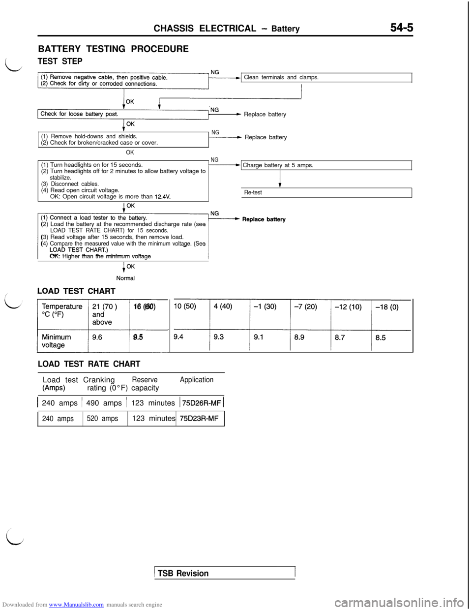
Downloaded from www.Manualslib.com manuals search engine CHASSIS ELECTRICAL - Battery54-5BATTERY TESTING PROCEDURE
LTEST STEP
Clean terminals and clamps.
- Replace battery
(1) Remove hold-downs and shields.(2) Check for broken/cracked case or cover.
OK
NG- Replace battery
(1) Turn headlights on for 15 seconds.
NG(2) Turn headlights off for 2 minutes to allow battery voltage to- Charge battery at 5 amps.
stabilize.
(3) Disconnect cables.(4) Read open circuit voltage.
IOK: Open circuit voltage is more than
12.4V.Re-test(2) Load the battery at the recommended discharge rate (see
LOAD TEST RATE CHART) for 15 seconds.(3) Read voltage after 15 seconds, then remove load.
(4) Compare the measured value with the minimum voltage. (SeeOK: Higher than the minimum voltage
i
Normal
LL16 (60)
9.5
LOAD TEST RATE CHARTLoad test Cranking
Reserve
W-w)rating (0°F) capacity
Application
1 240 amps / 490 amps / 123 minutes 1 75D26R-MF 1
240 amps520 amps123 minutes 75D23R-MF
1 TSB Revision1
Page 502 of 738
Downloaded from www.Manualslib.com manuals search engine 54-6CHASSIS ELECTRICAL - Ignition Switch
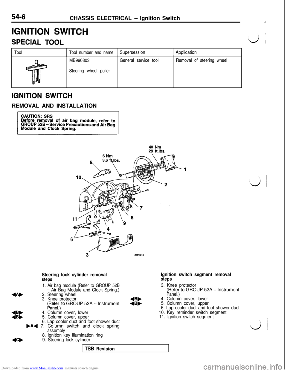
IGNITION SWITCHSPECIAL
TOOL
ToolTool number and nameSupersessionApplication
MB990803
Steering wheel pullerGeneral service toolRemoval of steering wheel
IGNITION SWITCHREMOVAL AND INSTALLATION
40 Nm29 ft.lbs.6 Nm
6
Steering lock cylinder removalsteps
Ignition switch segment removalsteps
1. Air bag module (Refer to GROUP 52B
4Ab
- Air Bag Module and Clock Spring.)3. Knee protector
2. Steering wheel(Refer to GROUP 52A - Instrument
3. Knee protector
Panel.)
LRedE;)to GROUP 52A - Instrument:i:4. Column cover, lower
5. Column cover, upper
:::4. Column cover, lower6. Lap cooler duct and foot shower duct
5. Column cover, upper10. Key reminder switch segment
6. Lap cooler duct and foot shower duct11. Ignition switch segment
,A+ 7. Column switch and clock springassembly
NW
8. Ignition key illumination ring
9. Steering lock cylinder
TSB Revision
Page 503 of 738
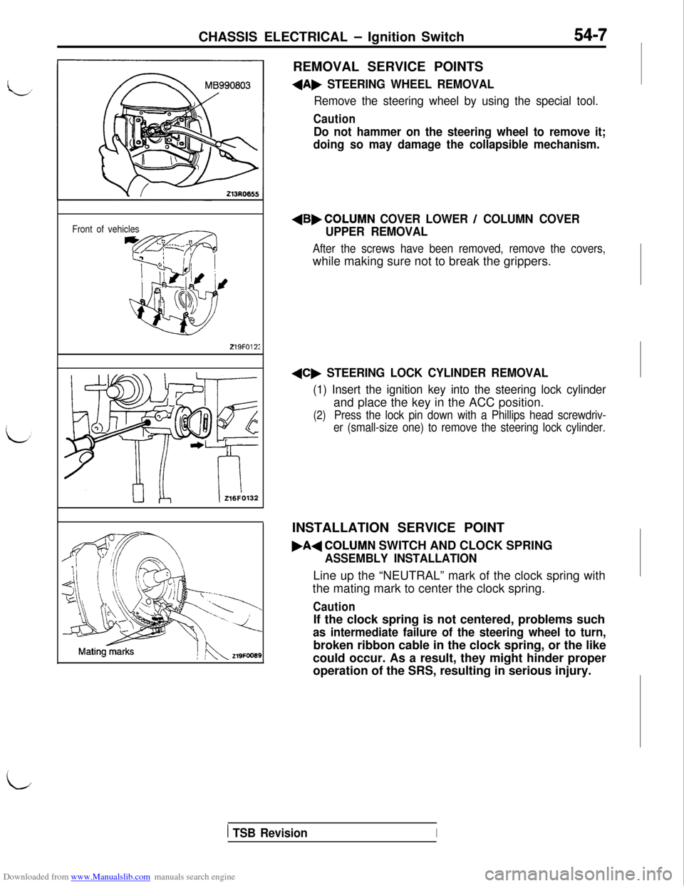
Downloaded from www.Manualslib.com manuals search engine CHASSIS ELECTRICAL - Ignition Switch54-7REMOVAL SERVICE POINTS
+A, STEERING WHEEL REMOVAL
Remove the steering wheel by using the special tool.
Caution
Do not hammer on the steering wheel to remove it;
doing so may damage the collapsible mechanism.
Front of vehicles
219FO12:
+B,COLUMN COVER LOWER / COLUMN COVER
UPPER REMOVAL
After the screws have been removed, remove the covers,while making sure not to break the grippers.
+C, STEERING LOCK CYLINDER REMOVAL
(1) Insert the ignition key into the steering lock cylinderand place the key in the ACC position.
(2)Press the lock pin down with a Phillips head screwdriv-
er (small-size one) to remove the steering lock cylinder.INSTALLATION SERVICE POINT
.A+COLUMN SWITCH AND CLOCK SPRING
ASSEMBLY INSTALLATIONLine up the “NEUTRAL” mark of the clock spring with
the mating mark to center the clock spring.
CautionIf the clock spring is not centered, problems such
as intermediate failure of the steering wheel to turn,broken ribbon cable in the clock spring, or the like
could occur. As a result, they might hinder proper
operation of the SRS, resulting in serious injury.
iI
1 TSB RevisionI
Page 504 of 738
Downloaded from www.Manualslib.com manuals search engine 54-8CHASSIS ELECTRICAL - Ignition Switch
216AO57000002296INSPECTION
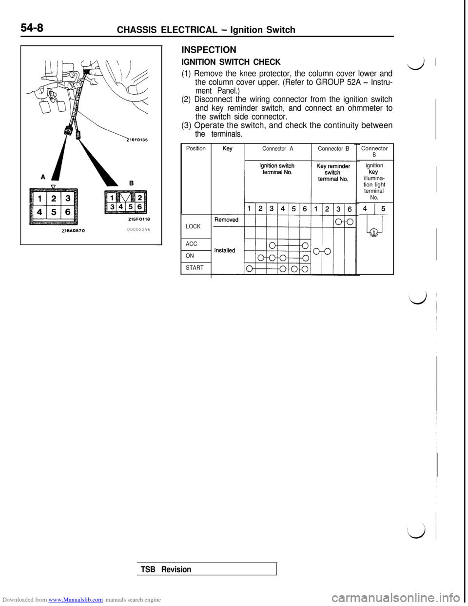
IGNITION SWITCH CHECK
(1) Remove the knee protector, the column cover lower andd’
the column cover upper. (Refer to GROUP 52A - Instru-
ment Panel.)
(2) Disconnect the wiring connector from the ignition switch
and key reminder switch, and connect an ohmmeter to
the switch side connector.(3) Operate the switch, and check the continuity between
the terminals.
PositionKeyConnector AConnector B
LOCK
ACC
ON
START
ConnectorB
ignitionkey
illumina-
tion light
terminal
No.
415
LJ
TSB Revision
Page 505 of 738
Downloaded from www.Manualslib.com manuals search engine CHASSIS ELECTRICAL - Meters and Gauaes
(/
METERS AND GAUGES
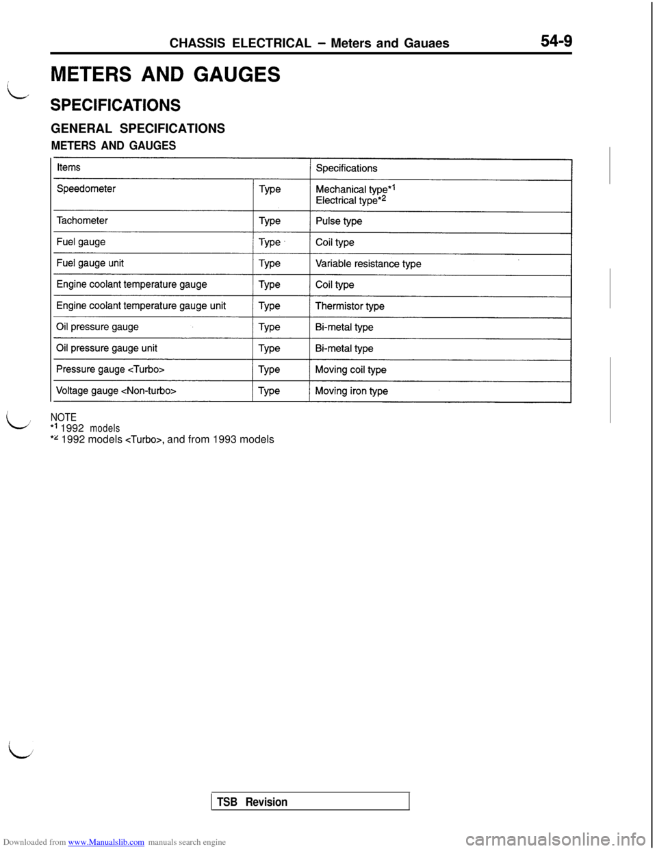
SPECIFICATIONSGENERAL SPECIFICATIONS
METERS AND GAUGES
LNOTE*’ 1992
models
*z 1992 models , and from 1993 models
TSB Revision
Page 506 of 738
Downloaded from www.Manualslib.com manuals search engine 54-I 0CHASSIS ELECTRICAL - Meters and Gauges
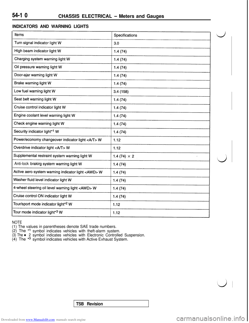
INDICATORS AND WARNING LIGHTS
Anti-lock brakin
NOTE(1) The values in parentheses denote SAE trade numbers.
(2) The *I
(3) The l 2symbol indicates vehicles with theft-alarm system.(4) The
*3
symbol indicates vehicles with Electronic Controlled Suspension.symbol indicates vehicles with Active Exhaust System.
TSB Revision
Page 507 of 738
Downloaded from www.Manualslib.com manuals search engine CHASSIS ELECTRICAL - Meters and Gauaes
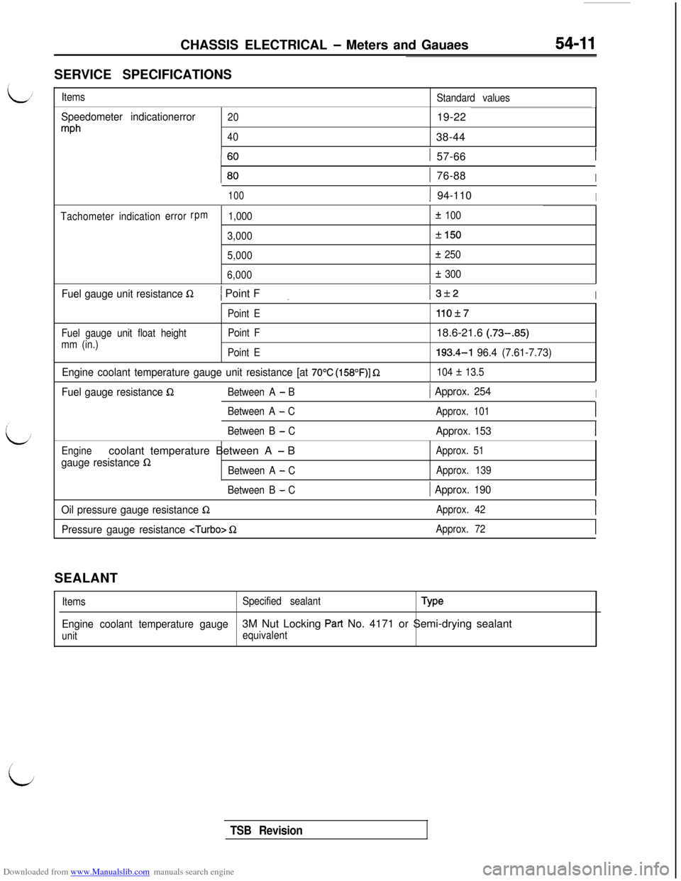
SERVICE SPECIFICATIONS
Items
Standard values
Speedometer indicationerror
mph
2019-22
4038-44
1 57-66
1 76-88I
1001 94-110I
Tachometerindicationerrorrpm1,000f 100
3,000
f150
5,000f 250
6,000
Ik 300
Fuel gauge unit resistance R/ Point F_I3f2I
Point E
Fuel gauge unit float heightPoint F
mm (in.)
Point E
Engine coolant temperature gauge unit resistance [at 70°C (158”F)] Q110+7
18.6-21.6 (.73-.85)193.4-l
96.4 (7.61-7.73)
104 f 13.5
Fuel gauge resistance QBetween A - B/ Approx. 254I
Between A - CApprox. 101I
Between B - CApprox. 153I
Enginecoolant temperature Between A - B
gauge resistance QBetween A - CApprox. 51
Approx. 139
Between B
- C/ Approx. 190I
Oil pressure gauge resistance QApprox. 42I
Pressure gauge resistance QApprox. 72ISEALANT
ItemsSpecified sealantType
Engine coolant temperature gauge3M Nut Locking Part No. 4171 or Semi-drying sealant
unitequivalent
TSB Revision
Page 508 of 738
Downloaded from www.Manualslib.com manuals search engine 54-12CHASSIS ELECTRICAL - Meters and Gauges
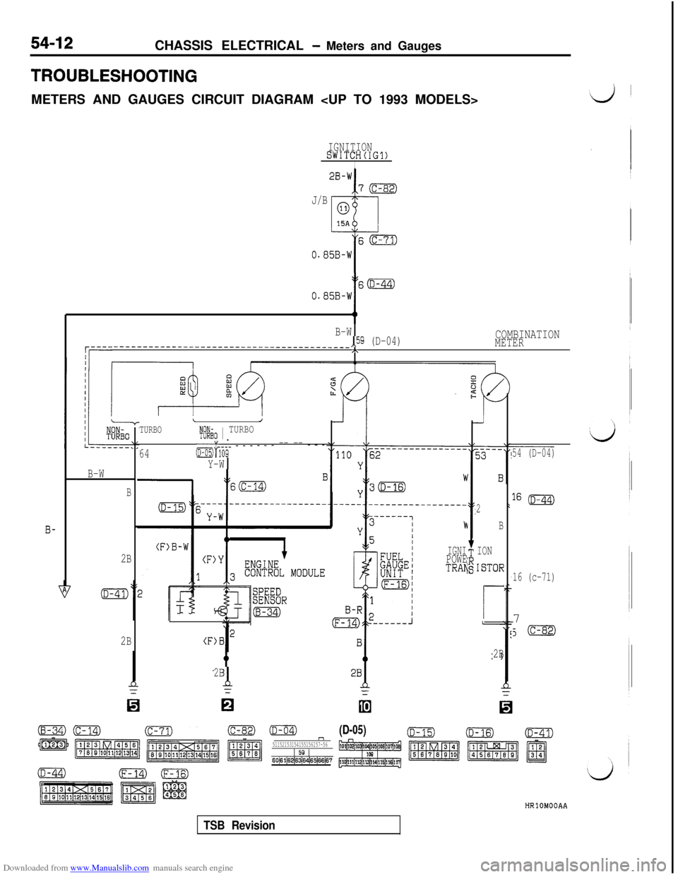
TROUBLESHOOTINGMETERS AND GAUGES CIRCUIT DIAGRAM
IGNITIONSWITCH(IG1)I
J/B
I60
0.05B-W
t
S(D-44)
O.B5B-W
B-W,,59 (D-04)COMBINATION
q----_____----____-_------~~~~~--~-------~~~~~METER,\
r--t-- I
2
B
ION
ISTOR
r
2B
TURBOLJt@io 1 TURBO
64&&- - - - - - - -- -- - - -
Y-W
54 (D-04)
16 (D-44)
16 (c-71)7
J(c-82)
B-W
B
b
IGNIPOWETRAN
(F)B
B-
2B
2B
2Bd
0
(c-82)mn51152153154155156157~561 59 160~61~62~S~s4~65~66~6?
(D-05)HRlOMOOAA
TSB Revision
Page 509 of 738
Downloaded from www.Manualslib.com manuals search engine CHASSIS ELECTRICAL - Meters and Gauges54-13
;i;k\IGHT
I1.25R-Wr-h
0;;&CATED
J/B
B-h
A0
1
II----B-YY-R
s2@
>L
(4
/
‘Ei
?
c
.
,%l
(B-OS)
r
-7-l
COMBINATION
GAUGE
(D-09)!
5
/
-
-
F
I
ENGIN'ECONTROL MODULE
OILPRESSURE
E#F"
(B-36)HRlOMOOAB
ENGINECOOLANT
TEMPERATURE
GAUGE UNIT
(B-01)
TSB Revision
Page 510 of 738
Downloaded from www.Manualslib.com manuals search engine CHASSIS ELECTRICAL - Meters and Gauaes
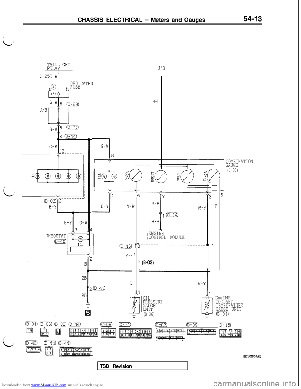
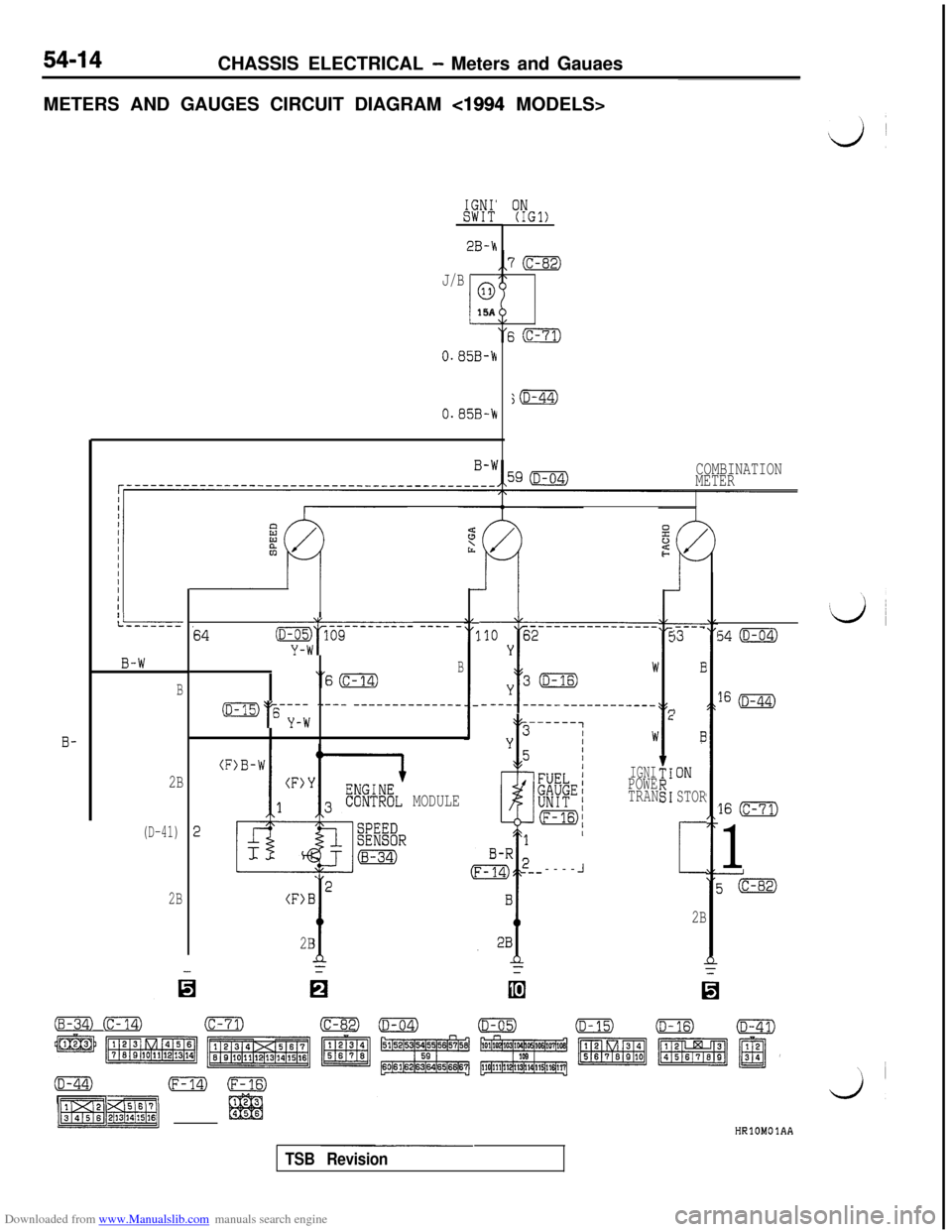
METERS AND GAUGES CIRCUIT DIAGRAM
cl994 MODELS>
IGNI'SWIT
J/B
i
015A
ON(IGl)
0.85B-h
0.85B-h
COMBINATION
METER
IL:------64~w:~5G------ ---- -
‘SmB
m‘I'"-,Tw ---- -------_-----_
----i3
B
)
?
ON
STOR
c
2B
-------_--______.lO 62Y
I------
Wy3m
34 (D-04)
16 (D-44)
16 m
1
B-W
B- ---, ----- ------------
W
IGNIPOWE
TRAN
B-
(F
2
2B
(D-41)
MODULE
-----
J
2(F>B
t2B-
2B
(c-82)mm (c-14)(c-71)
=plzF@gjm
m(F-14)-rE$FTg
p$JHRlOMOlAA
TSB Revision
Trending: washer fluid, cd storage, compression ratio, ESP inoperative, wheel, water pump, manual transmission
