switch MITSUBISHI 3000GT 1995 2.G Workshop Manual
[x] Cancel search | Manufacturer: MITSUBISHI, Model Year: 1995, Model line: 3000GT, Model: MITSUBISHI 3000GT 1995 2.GPages: 738, PDF Size: 35.06 MB
Page 639 of 738
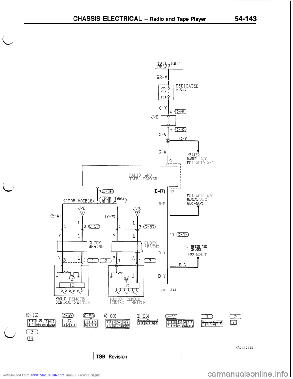
Downloaded from www.Manualslib.com manuals search engine CHASSIS ELECTRICAL - Radio and Tape Player54-143
i@;X&GHT
-i-q-
.HEATER.MANUAL A/C.FULL AUTO A/C
RADIO AND
TAPE PLAYER
L1
------.
Y
t
L
. .i
t
(D-47)
B-E
1
CLOCK
SPRING
_IB-k
0
?ADIO REMOTE:ONTROL SWITCHRADIO REMOTE
CONTROL SWITCH
0-Y
RHE
3
---212.FULL AUTO A/C.MANUAL A/C.ELC-4A/T
1
.1 (c-15)
. ,$&AND
.FOG LIGHT
'TAT
HR14M04BB
TSB Revision
Page 640 of 738
Downloaded from www.Manualslib.com manuals search engine 54-144CHASSIS ELECTRICAL - Radio and Tape Player
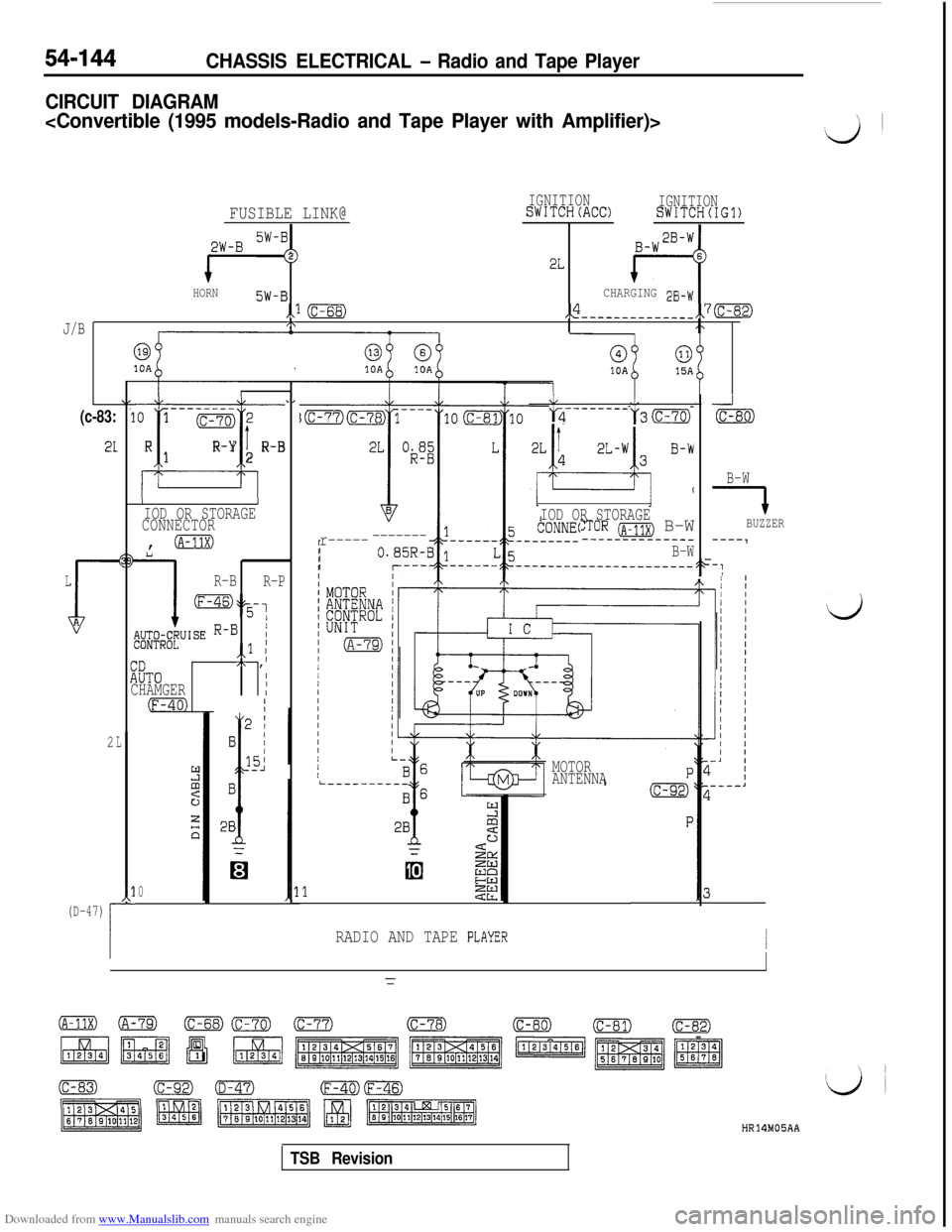
CIRCUIT DIAGRAM
d’
FUSIBLE LINK@IGNITIONSWITCH(ACC)IGNITIONSWITCH(IG1)
p&J-B SW-i
1
22L
HORN5W-BCHARGING 33-W
,,I (c-68),$-----------___,,7(c-82)
J/BI\
@10A
(c-83:
21
L
$A
2
‘1--------01 (c-70)2
i
RR-Yt1R-B2
L------__l-2y3(c-70)
_J
(c-80)
IIIOD OR STORAGE
CONNECTOR,
0L
1
R-B
R-P
my,
;;;4i;eUISE R-B1,,l I
:ZiTO
I,\ ,I
CHAMGERI
(F-40) '
L
*l-(D-47)
i
r.l
E
;
2ec
0
I
IOD OR STORAGE:TOR (~-11~) B-W--------_--___
B-WB-W
7BUZZER
----1r------------IIIF-:
MOTORi----_-_---ANTENNA
RADIO AND TAPE PLAYERI
d
HR14MOSAA
TSB Revision
Page 642 of 738
Downloaded from www.Manualslib.com manuals search engine 54-146CHASSIS ELECTRICAL - Radio and Tape Player
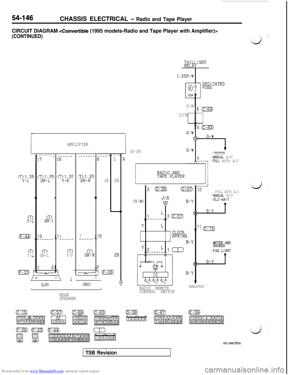
CIRCUIT DIAGRAM
(CONTINUED)
tT:i2E
--------71
i (%-i?
4
:*tL2'
CT)GR-1
15.------,/l6--__--
CT)Y-JCT)GR-L
L
(LH)
AMPLIFIER
_-----a
CT>Y-F
-_------E
5:T~R12-t
0
2B
a7---___,,l
(T)GR-r.?
1I‘4d(F-(-
(RH)\/
REAR
SPEAKER---
1
E
2B
28
/
1.25R-W
G-W,,6 (c-69)J/B
n
(E-39). HEATER.MANUAL A/C*FULL AUTO A/C
I
. FULL AUTO A/C.MANUAL A/C.ELC-4A/T
RADIO REMOTERHEOSTAT
CONTROL SWITCH
HR14M05BA
TSB Revision
Page 644 of 738
Downloaded from www.Manualslib.com manuals search engine 54-148CHASSIS ELECTRICAL - Radio and Tape Player
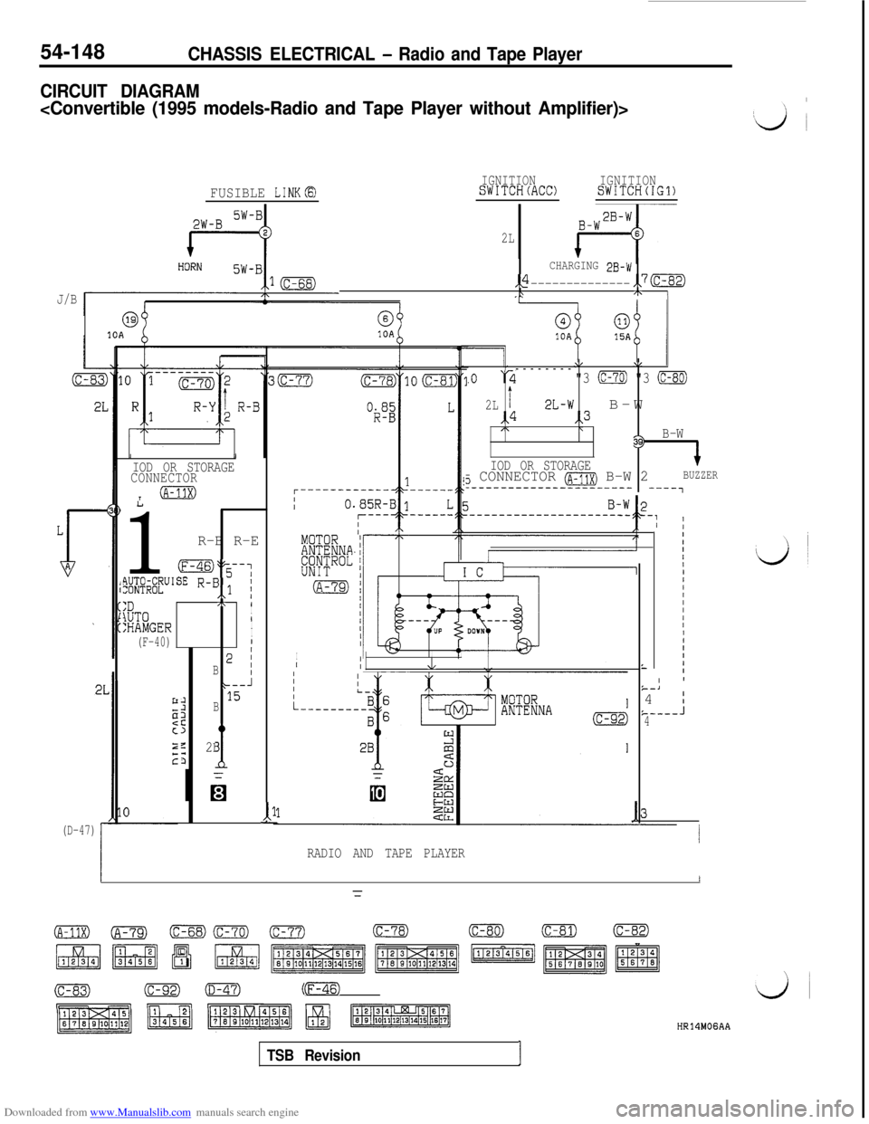
CIRCUIT DIAGRAM
J/B
FUSIBLE LINKB
69@10A10A
(D-47)
III
IOD OR STORAGE
CONNECTOR
T@m
1
R-B R-E
oy-;
flW&UISE R-B,,l i
:D,\ 1
lUT0I
:HAMGER/I
(F-40)II
B2 i
* J
:15B
z
c
z2B
d
2L
CHARGING 2B-w
,,4--------------,,7(c-82)\+ I
11-
IGNITIONSWITCH(ACC)IGNITIONSWITCH(IG1)
\/\/--------
.o ‘2"3 (c-70) "3 (c-80)
2Lt2L-wB-W,,4,,3/\\39)B-W
IOD OR STORAGE
+
3 CONNECTOR (A-11X) B-W 2BUZZER_---------------------- ----,
I
,IIIIII,II/IIIIIIIIIL
RADIO AND TAPE PLAYER
L
IIIIII/IIIIIIIII1IIIII ’k--J4 I&-----J4
I
=
o(A-79)(c-68)Gm) (c-77)(c-78)(c-80)(c-81)(c-82)
(c-83)(C-92)0mm)(F-46)
TSB RevisionI
HR14MOGAA
Page 645 of 738
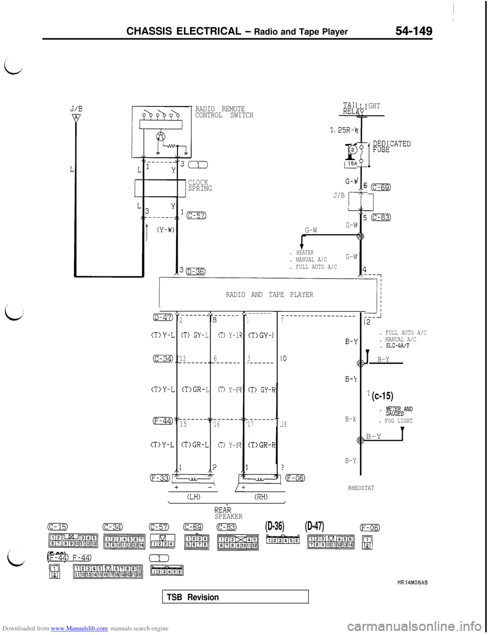
Downloaded from www.Manualslib.com manuals search engine CHASSIS ELECTRICAL - Radio and Tape Player
RADIO REMOTE
CONTROL SWITCHKK1
1.25R-kr
@
GHT
1
;@ATED
i
I6CLOCKSPRINGJ/B
r
. FULL AUTO A/C
G-WG-W
. HEATER. MANUAL A/CG-W
. FULL AUTO A/C
. MANUAL A/C
. ELC-4A/T
1B-Y RADIO AND TAPE PLAYER
i
I-----_OV -“,----_-v------281
(T)Y-LCT) GY-:LCT> Y-li(T>GY-I
_---_----___--____7
(c-34),: .,~1363_-----_------__------
(T>Y-L(T>GR-LCT> Y-F(T> GY-I
_----__------.(F-44)>? q'-.------15161718B-k
(T>Y-L 2(T)GR-ICT> Y-F(T>GR-F
B-Y1
-m
1:2/\
mz7LL/-I:
+-/+
(LH)(RH)\/
RHEOSTAT
,l (c-15)
. b&&&AND
. FOG LIGHTB-Y
1
REAR
SPEAKER
(c-15)(c-34)(c-57)00(D-36)(D-47)(F-06)
c ~~~~1~1~~~
(F-33)Fm)
mB(iisiEa
HR14MOGAB
TSB Revision
Page 650 of 738
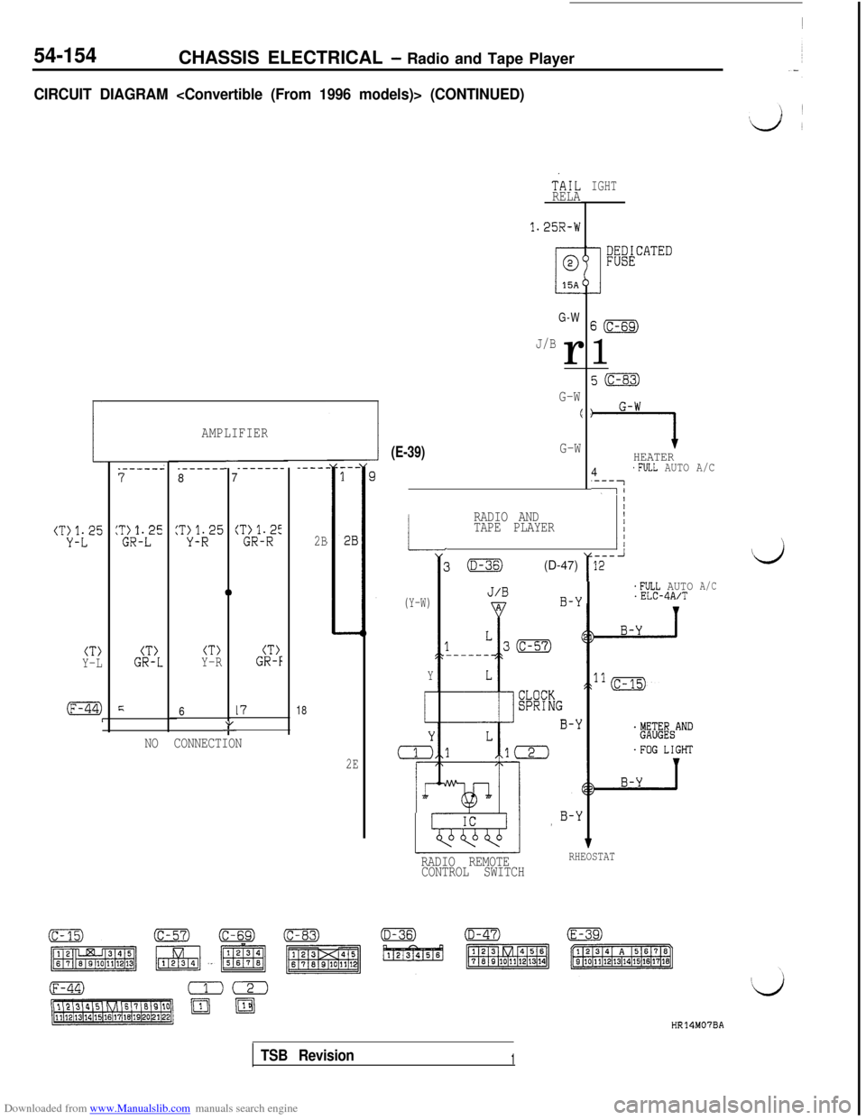
Downloaded from www.Manualslib.com manuals search engine 54-154CHASSIS ELECTRICAL - Radio and Tape Player
CIRCUIT DIAGRAM
(T:Jt25
--7
i
0
CT>CT>CT>CT>Y-LGR-LY-RGR-F
F61718"-
AMPLIFIER
.------8_-----_----L
2B
NO CONNECTION
2E
(E-39)G-W
TiIL
RELA
1.25R-W
G-W
J/Br
G-W
(
-L
(Y-W)
Y
i
r
rr
RADIO AND_ 11TAPE PLAYER
---3(D-36)(D-47)r12 i
IGHT
S(c-69)
1
7HEATER
4'FULL AUTO A/C
'---7-1
*FULL AUTO.ELC-4A/T
RADIO REMOTERHEOSTAT
CONTROL SWITCH
A/C
HR14M07BA
TSB Revision1
Page 660 of 738
Downloaded from www.Manualslib.com manuals search engine 54-164CHASSIS ELECTRICAL - Radio and Tape Player
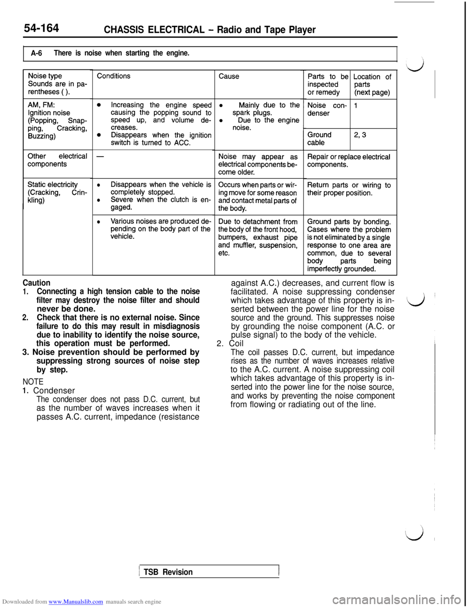
A-6There is noise when starting the engine.
Noise type
Sounds are in pa-
rentheses ( ).
AM, FM:
Ignition noise
(Popping, Snap-
ping,Cracking,
Buzzing)
Otherelectrical
components
Static electricity
(Cracking, Crin-
kling)
Conditions
0Increasing the engine speedcausing the popping sound tospeed up, and volume de-creases.0Disappears when the ignitionswitch is turned to ACC.
-
lDisappears when the vehicle is
completely stopped.Occurs when parts or wir-
Severe when the clutch is en-ing move for some reasonlgaged.and contact metal parts of
the body.
lVarious noises are produced de-pending on the body part of thevehicle.
Due to detachment from
the body of the front hood,
bumpers, exhaust pipe
and muffler, suspension,
etc.
Causel
Mainly due to the
spark plugs.l Due to the enginenoise.
Noise may appear as
electrical components be-
come older.
Parts to be Location of
inspectedparts
or remedy(next page)
Noise con- 1
denser
Ground
cable2, 3
Repair or replace electricalcomponents.
Return parts or wiring to
their proper position.
Caution
1.Connecting a high tension cable to the noise
filter may destroy the noise filter and shouldnever be done.
2.Check that there is no external noise. Since
failure to do this may result in misdiagnosis
due to inability to identify the noise source,
this operation must be performed.3. Noise prevention should be performed by
suppressing strong sources of noise step
by step.
NOTE
1. Condenser
The condenser does not pass D.C. current, butas the number of waves increases when it
passes A.C. current, impedance (resistanceagainst A.C.) decreases, and current flow is
facilitated. A noise suppressing condenser
which takes advantage of this property is in-
serted between the power line for the noise
source and the ground. This suppresses noiseby grounding the noise component (A.C. or
pulse signal) to the body of the vehicle.
2. Coil
The coil passes D.C. current, but impedance
rises as the number of waves increases relativeto the A.C. current. A noise suppressing coil
which takes advantage of this property is in-
serted into the power line for the noise source,
and works by preventing the noise componentfrom flowing or radiating out of the line.
1 TSB Revision
Ground parts by bonding.
Cases where the problem
is not eliminated by a single
response to one area are
common, due to several
bodypartsbeing
imperfectly grounded.
Page 662 of 738
Downloaded from www.Manualslib.com manuals search engine 54-166CHASSlS ELECTRICAL - Radio and Tape Player
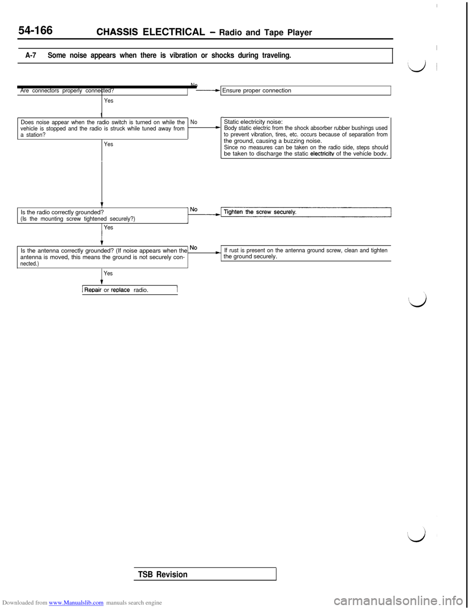
IA-7Some noise appears when there is vibration or shocks during traveling.
‘d ~
Are connectors properly connected?
YesNo
---+ Ensure proper connection
t
Does noise appear when the radio switch is turned on while theNovehicle is stopped and the radio is struck while tuned away fromLa station?
YesStatic electricity noise:
Body static electric from the shock absorber rubber bushings used
to prevent vibration, tires, etc. occurs because of separation fromthe ground, causing a buzzing noise.
Since no measures can be taken on the radio side, steps shouldbe taken to discharge the static electricitv of the vehicle bodv.
tIs the radio correctly grounded?
(Is the mounting screw tightened securely?)
1 Yes
tIs the antenna correctly grounded? (If noise appears when the Nocantenna is moved, this means the ground is not securely con-
nected.)
If rust is present on the antenna ground screw, clean and tightenthe ground securely.
Yes
1 Reoair or reolace radio.1
TSB Revision
Page 663 of 738
Downloaded from www.Manualslib.com manuals search engine CHASSIS ELECTRICAL - Radio and Tape Player54-167
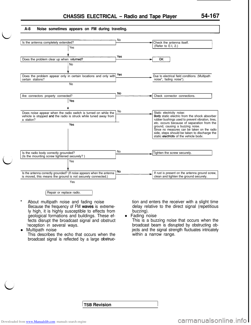
A-8Noise sometimes appears on FM during traveling.
NoIs the antenna completely extended?
Yes
t Check the antenna itself.
(Refer to E-l, 2.)
+Does the problem clear up whenre
1 No
Yes
iDoes the problem appear only in certain locations and only with yes
certain stations?
No
~ Due to electrical field conditions. (Multipath
noise*, fading noise*).
Are connectors property connected?
Yes
Check connector connections.1
tDoes noise appear when the radio switch is turned on while the
vehicle is stopped
and the radio is struck while tuned away froma station?
Yes
No*Static electricity noise:Sody static electric from the shock absorberrubber bushings used to prevent vibration, tires,etc. occurs because of separation from the
ground, causing a buzzing noise.
Since no measures can be taken on the radioside, steps should be taken to discharge the
static
electricitv of the vehicle bodv.
Is the radio body correctly grounded?
No(Is the mounting screw tightened securely?
)
Yes
-) Tighten the screw securely.I
Is the antenna correctly grounded? (If noise appears when the antennais moved, this means the ground is not securely connected.)
Yes
If rust is present on the antenna ground screw,clean and tighten the ground securely.
*
1 Repair or replace radio.1
About multipath noise and fading noise
Because the frequency of FM waves is extreme-
ly high, it is highly susceptible to effects from
geological formations and buildings. These ef-
fects disrupt the broadcast signal and obstruct
‘reception in several ways.l Multipath noise
This describes the echo that occurs when the
broadcast signal is reflected by a large obstruc-
tion and enters the receiver with a slight time
delay relative to the direct signal (repetitious
buzzing).l Fading noise
This is a buzzing noise that occurs when the
broadcast beam is disrupted by obstructing ob-
jects and the signal strength fluctuates intricately
within a narrow range.
1 TSB Revision
Page 664 of 738
Downloaded from www.Manualslib.com manuals search engine 54-168CHASSIS ELECTRICAL - Radio and Tape Player
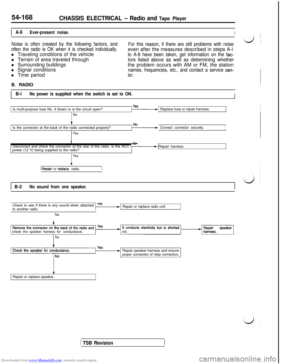
IA-9Ever-present noise.I
Noise is often created by the following factors, and
often the radio is OK when it is checked individually.l Traveling conditions of the vehicle
l Terrain of area traveled through
l Surrounding buildings
l Signal conditions
l Time periodFor this reason, if there are still problems with noiseeven after the measures described in steps A-l
to A-8 have been taken, get information on the fac-
tors listed above as well as determining whetherthe problem occurs with AM or FM, the station
names, frequencies, etc., and contact a service cen-
ter.B. RADIO
IB-lNo power is supplied when the switch is set to ON.IIIIs multi-purpose fuse No. 4 blown or is the circuit open?Replace fuse or repair harness.
NoIs the connector at the back of the radio connected properly?
Yes
Connect connector securely.1t
NoDisconnect and check the connector at the rear of the radio. Is the ACC / Repair harness.
power (12 V) being supplied to the radio?J
I
Yes
1 Reoair or reolace radio.
1 B-2No sound from one speaker.ICheck to see if there is any sound when attached
to another radio.
I-=----[Repair or replace radio unit.
No
checkthespeakerharnessfor conductance.
out.*Speakarj
NoRepair speaker harness and ensure
proper connection of relay connectors.
tRepair or replace speaker.
1 TSB Revision