switch MITSUBISHI 3000GT 1995 2.G Workshop Manual
[x] Cancel search | Manufacturer: MITSUBISHI, Model Year: 1995, Model line: 3000GT, Model: MITSUBISHI 3000GT 1995 2.GPages: 738, PDF Size: 35.06 MB
Page 674 of 738
Downloaded from www.Manualslib.com manuals search engine 54-178CHASSIS ELECTRICAL - Radio and TaDe Plaver
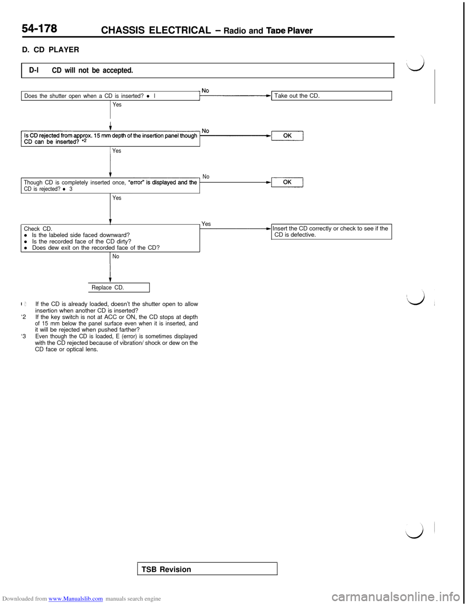
D. CD PLAYER
D-lCD will not be accepted.
Does the shutter open when a CD is inserted? l l
YesTake out the CD.
1 Yes
tThough CD is completely inserted once, “e
CD is rejected? l 3No-l
Yes
tCheck CD.l Is the labeled side faced downward?
l Is the recorded face of the CD dirty?
l Does dew exit on the recorded face of the CD?- Yes- Insert the CD correctly or check to see if the
CD is defective.
No
l 1‘2
‘3
tReplace CD.If the CD is already loaded, doesn’t the shutter open to allow
insertion when another CD is inserted?
If the key switch is not at ACC or ON, the CD stops at depth
of 15 mm below the panel surface even when it is inserted, andit will be rejected when pushed farther?
Even though the CD is loaded, E (error) is sometimes displayedwith the CD rejected because of vibration/ shock or dew on the
CD face or optical lens.
TSB Revision
Page 676 of 738
Downloaded from www.Manualslib.com manuals search engine CHASSIS ELECTRICAL - Radio and Taste Plaver
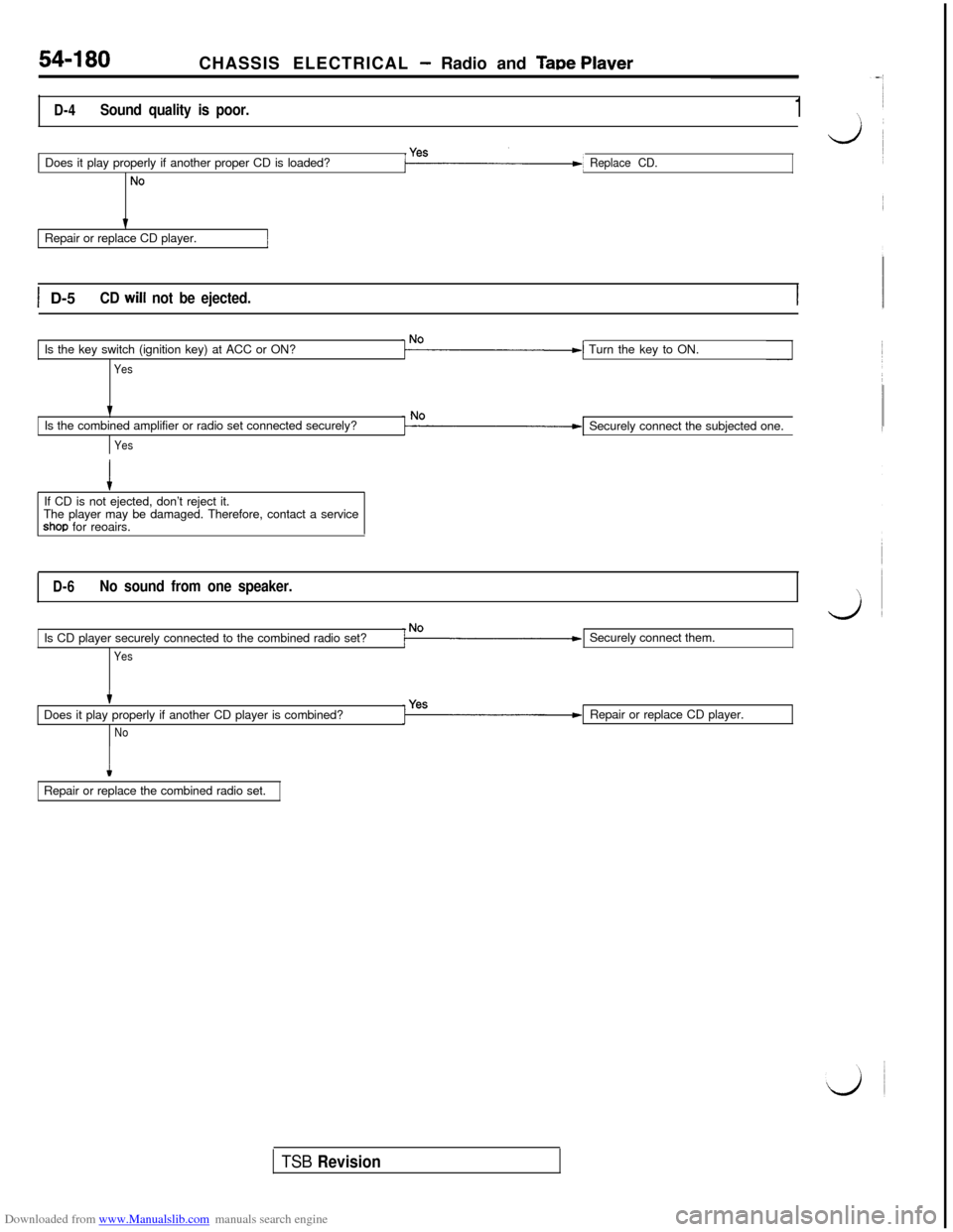
D-4Sound quality is poor.1Does it play properly if another proper CD is loaded?
No
Replace CD.Repair or replace CD player.
1 D-5CD will not be ejected.Is the key switch (ignition key) at ACC or ON?
YesTurn the key to ON.
tIs the combined amplifier or radio set connected securely?
YesSecurely connect the subjected one.
If CD is not ejected, don’t reject it.
The player may be damaged. Therefore, contact a service
shop for reoairs.
D-6No sound from one speaker.Is CD player securely connected to the combined radio set?
YesSecurely connect them.
Does it play properly if another CD player is combined?
NoRepair or replace CD player.
IRepair or replace the combined radio set.
TSB Revision
Page 677 of 738
Downloaded from www.Manualslib.com manuals search engine CHASSIS ELECTRICAL - Radio and Tape Player54-181
E. MOTOR ANTENNA
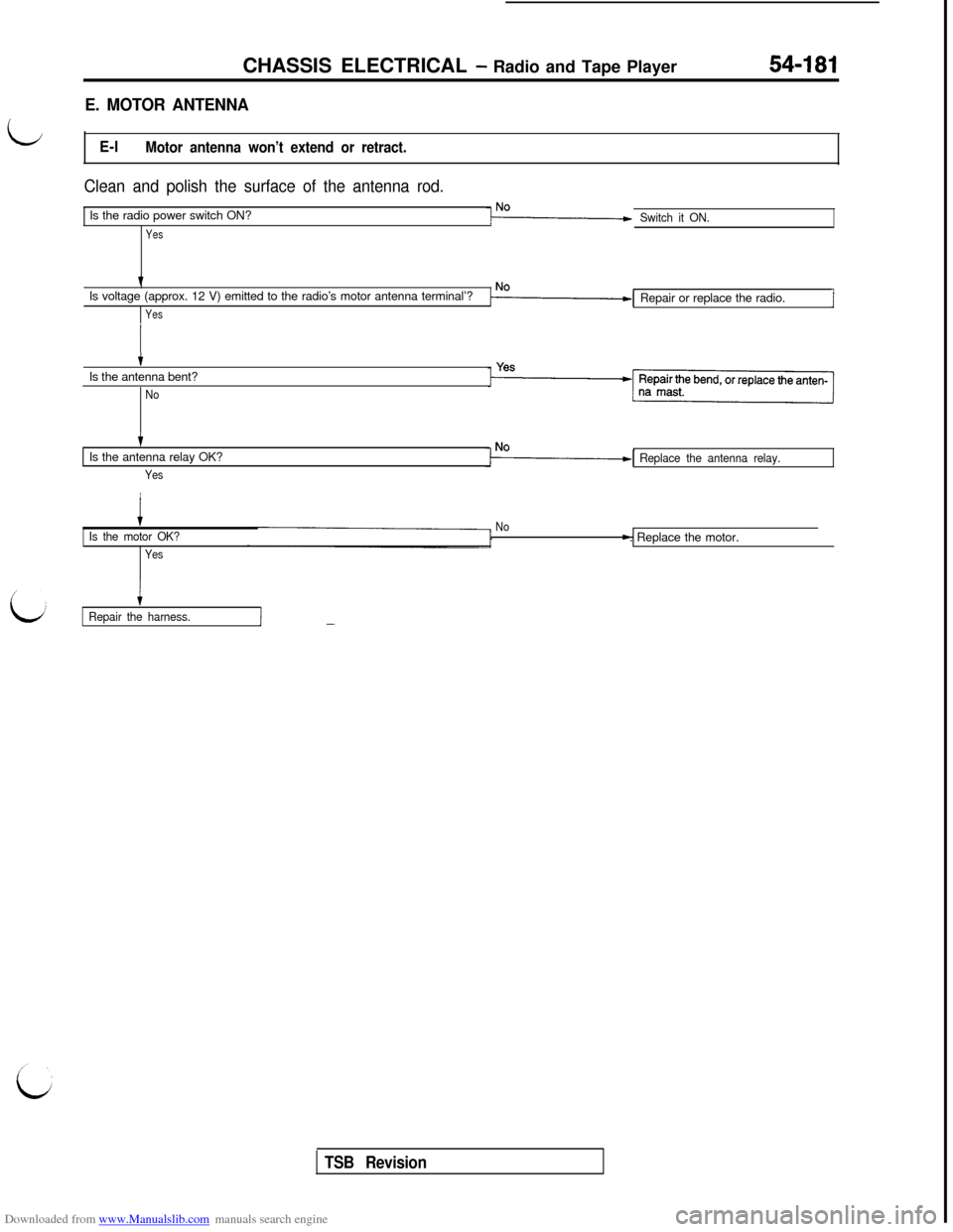
LE-lMotor antenna won’t extend or retract.
Clean and polish the surface of the antenna rod.Is the radio power switch ON?
Yes
Switch it ON.Is voltage (approx. 12 V) emitted to the radio’s motor antenna terminal’?
YesRepair or replace the radio.i
tIs the antenna bent?
No
tIs the antenna relay OK?
Yes
Replace the antenna relay.
iIs the motor OK?
YesNo
c
Repair the harness.I-
TSB Revision. Replace the motor.
Page 682 of 738
Downloaded from www.Manualslib.com manuals search engine 54-186
CHASSIS ELECTRICAL - Radio and Tape Player
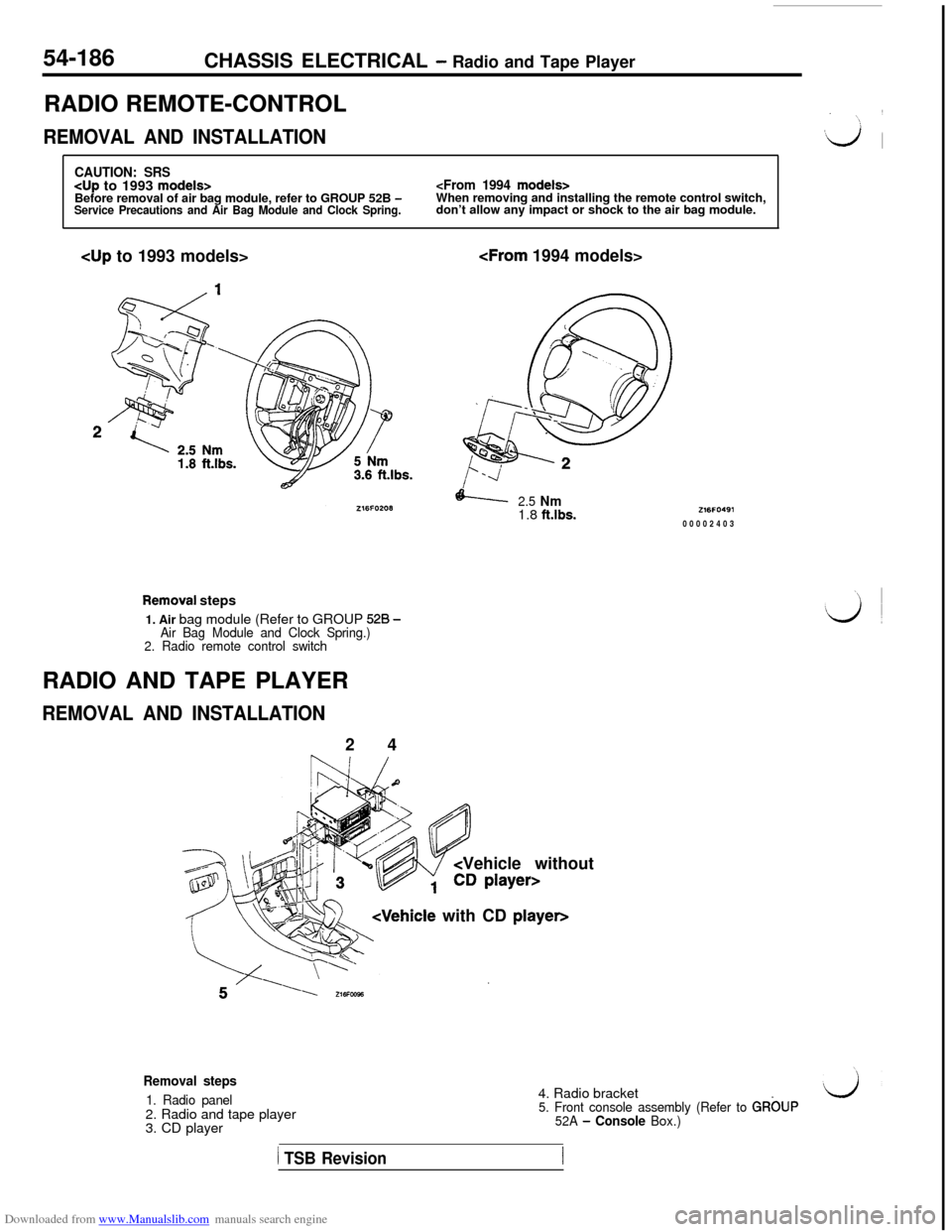
RADIO REMOTE-CONTROL
REMOVAL AND INSTALLATION
CAUTION: SRS
don’t allow any impact or shock to the air bag module.cup to 1993 models>
2.5 Nm1.8 ft.lbs.
Removai steps
1. Air bag module (Refer to GROUP
528 -Air Bag Module and Clock Spring.)
2. Radio remote control switchRADIO AND TAPE PLAYER
REMOVAL AND INSTALLATION2 4
Vehicle without
Z16FO49100002403
Removal steps
1. Radio panel2. Radio and tape player
3. CD player4. Radio bracket5. Front console assembly (Refer to GRbUP
52A - Console Box.)
1 TSB Revision
Page 685 of 738
Downloaded from www.Manualslib.com manuals search engine CHASSIS ELECTRICAL - Radio and Tape Player54-I 89
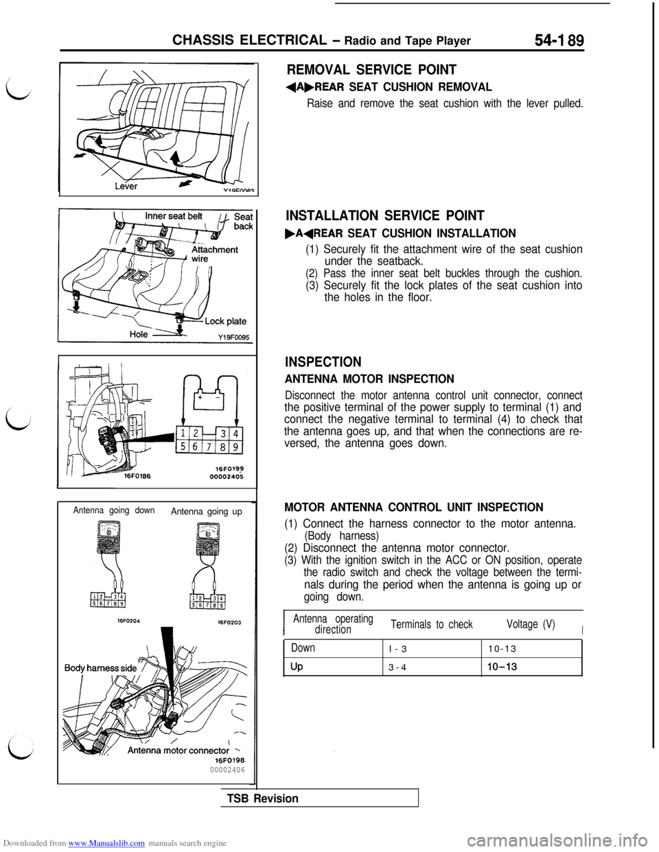
Antenna going downAntenna going up
16FO203
16F019800002406
REMOVAL SERVICE POINT
+A,REAR SEAT CUSHION REMOVAL
Raise and remove the seat cushion with the lever pulled.
INSTALLATION SERVICE POINT
.AqREAR SEAT CUSHION INSTALLATION
(1) Securely fit the attachment wire of the seat cushion
under the seatback.
(2) Pass the inner seat belt buckles through the cushion.
(3) Securely fit the lock plates of the seat cushion into
the holes in the floor.
INSPECTION
ANTENNA MOTOR INSPECTION
Disconnect the motor antenna control unit connector, connect
the positive terminal of the power supply to terminal (1) and
connect the negative terminal to terminal (4) to check that
the antenna goes up, and that when the connections are re-
versed, the antenna goes down.
MOTOR ANTENNA CONTROL UNIT INSPECTION
(1) Connect the harness connector to the motor antenna.
(Body harness)
(2) Disconnect the antenna motor connector.
(3) With the ignition switch in the ACC or ON position, operate
the radio switch and check the voltage between the termi-
nals during the period when the antenna is going up or
going down.
I
I
Antenna operating
directionTerminals to checkVoltage (V)
I
Down
UPl-310-13
3-410-13
TSB Revision
Page 686 of 738
Downloaded from www.Manualslib.com manuals search engine CHASSIS ELECTRICAL - Radio and Tape Player
Ring nut
Tbothsideofrack cable
Rack cable
16LO42700002407,8Loa1
7
Tooth side of rack cable
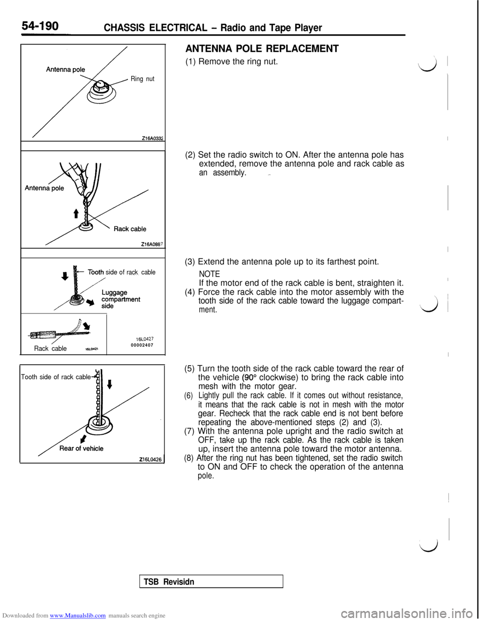
ANTENNA POLE REPLACEMENT(1) Remove the ring nut.
(2) Set the radio switch to ON. After the antenna pole has
extended, remove the antenna pole and rack cable as
an assembly._.(3) Extend the antenna pole up to its farthest point.
NOTEIf the motor end of the rack cable is bent, straighten it.
(4) Force the rack cable into the motor assembly with the
tooth side of the rack cable toward the luggage compart-
ment.(5) Turn the tooth side of the rack cable toward the rear of
the vehicle
(90” clockwise) to bring the rack cable into
mesh with the motor gear.
(6)Lightly pull the rack cable. If it comes out without resistance,
it means that the rack cable is not in mesh with the motor
gear. Recheck that the rack cable end is not bent before
repeating the above-mentioned steps (2) and (3).(7) With the antenna pole upright and the radio switch at
OFF, take up the rack cable. As the rack cable is takenup, insert the antenna pole toward the motor antenna.
(8) After the ring nut has been tightened, set the radio switchto ON and OFF to check the operation of the antenna
pole.
I
I
I
vi ~
I~
d
TSB Revisidn
Page 690 of 738
Downloaded from www.Manualslib.com manuals search engine 54-194CHASSIS ELECTRICAL - Rear Window Defogger
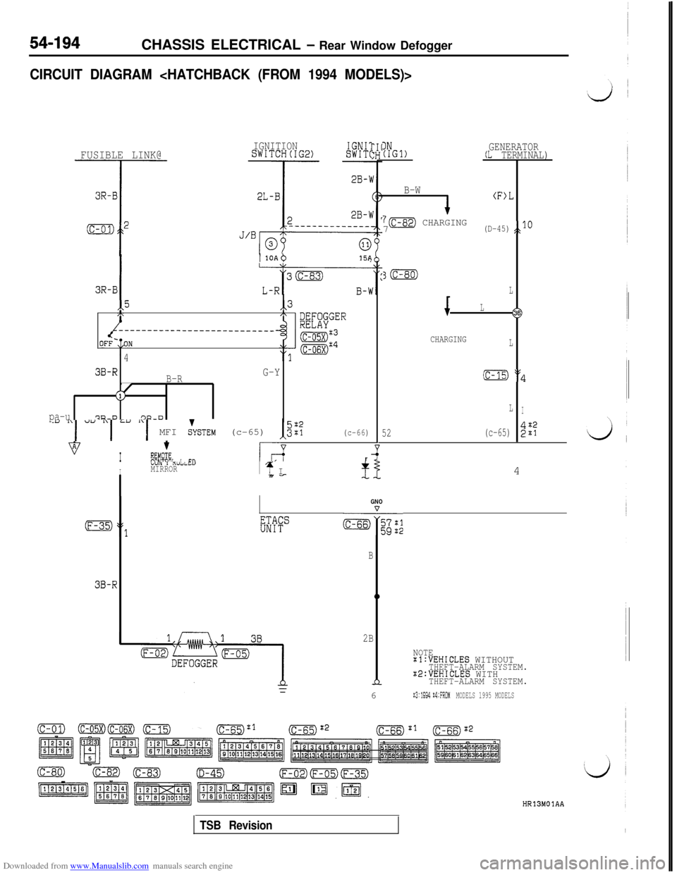
CIRCUIT DIAGRAM
FUSIBLE LINK@IGNITIONSWITCH(IG2)IGNIlSWIT(
I1 1OAb15A
3R-BI
,,5,,3/\,\
imGER------_____---______--~~~~~
OFF-,=ON
'4
3B-R
B-RG-Y
J(1,
pa-u7?a-D'3u-0
.y "I u" "I =" :‘I MFI &STEM (c-65) I,"::(c-66)
vI
t
%!E, i Cl?L-7r
IbUI” I KUl2~C”MIRRORI4 I7i7-
IN(IGl)GENERATOR(L TERMINAL)
B-W
(F>L
7m CHARGING7(D-45)JO
3m
L
L
16s)
CHARGINGL
(c-15) :$
LI
52(c-65)2%4
GNO
EWc&+;;;
B
3B-R0
2B
NOTEal:VEHICLES WITHOUTTHEFT-ALARM SYSTEM.X2:VEHICLES WITHnTHEFT-ALARM SYSTEM.6
:3:1994 :4:FROMMODELS 1995 MODELS
HR13MOlAA
TSB Revision
Page 692 of 738
Downloaded from www.Manualslib.com manuals search engine 54-196CHASSIS ELECTRICAL - Rear Window Defogger
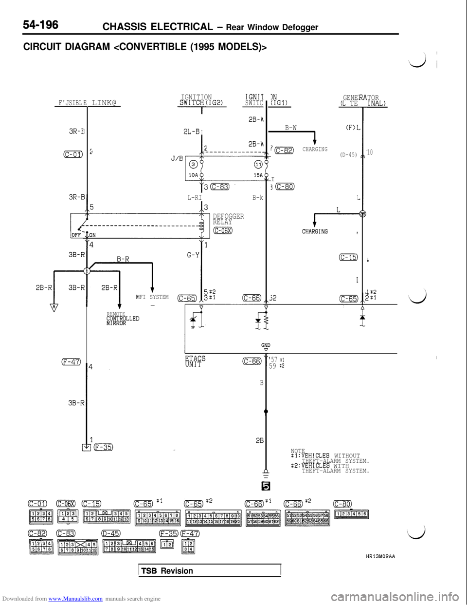
CIRCUIT DIAGRAM
F'JSIBLELINK@
3R-I3
(c-01)22B-h,-----------___.
3R-E
3B-F
38-F
IGNITIONIGNIlSWITCH(IG2)SWITC
- -
2L-BI
28-h
J’Bp
L-RIB-k
DEFOGGER
RELAY
(c-06x)
MFI SYSTEM3;:(c-66)-
REMOTE#JJ&LLED
GNIn
B
!B
INGENE(IGl)(L TE
B-W(F>I
7mCHARGINGI(D-45)
30
I
e-CHARGINGT
(c-15)
52
TORINAL)
10
'57 :1I
59 $2
NOTE:l:VEHICLES WITHOUTTHEFT-ALARM SYSTEM.22:VEHICLES WITHTHEFT-ALARM SYSTEM.
HR13M02AA
1 TSB Revision
Page 693 of 738
Downloaded from www.Manualslib.com manuals search engine CHASSIS ELECTRICAL - Rear Window Defogger
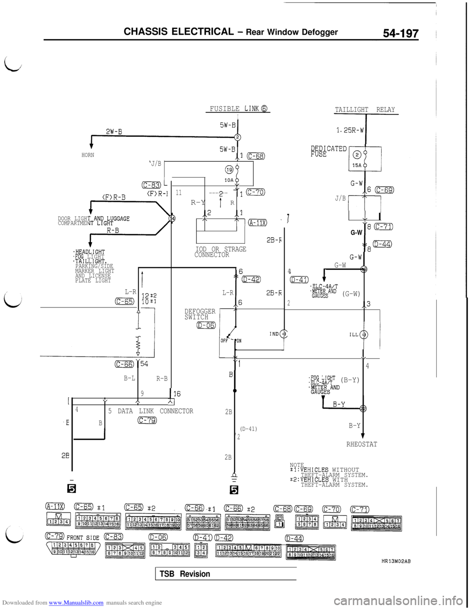
ii
2W-B
5W-BHORN
‘J/B,.1 (c-68)
(F>R-B(F>R-I
DOOR LIGHT AND LUGGAGE
COMPARTMENT LIGHT
:I,
,HEADLIGHT.FOG LIGHT.TAILLIGHT.PARKING/SIDE
MARKER LIGHT
AND LICENSE
PLATE LIGHT
69
10A\/
11------ A/1R-Y
r R
(c-70)
/L-R
cc-65)
f
i
I
,E
2B
FUSIBLE LINKa
I
1,,2 ,,l/\,--(A-11X) (
2B-F
IOD OR STRAGE
CONNECTOR
DEFOGGER
SWITCH
iD-os)
i
my54
B-L
R-B
9I16"AA\(
45 DATA LINK CONNECTOR
B(c-79)
i
L-R
V
1'4
:;fE-$;T (B-Y).$;;EESAND
2B
,(D-41)B-Y
27
RHEOSTAT
2B
h
n
NOTE:l:VEHICLES WITHOUTTHEFT-ALARM SYSTEM.:2:VEHICLES WITHTHEFT-ALARM SYSTEM.
2B-k
\6
IND(UN
TAILLIGHT RELAY
q-
:;&"A'""
J/B
7L IIG-W
I
8cc-71)
p@
G-W4
Ed.ELC-4A/T
'i;$$SAND (G-W)
2,,3
HR13M02AB
TSB Revision
Page 694 of 738
Downloaded from www.Manualslib.com manuals search engine 54-I 98CHASSIS ELECTRICAL - Rear Window Defogger
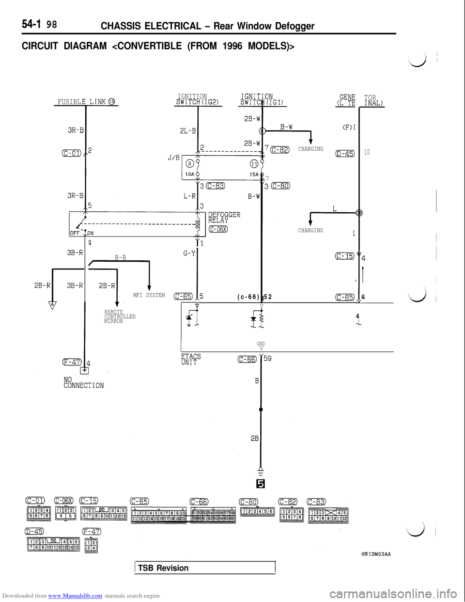
CIRCUIT DIAGRAM
2B-RFUSIBL
3R-I
(c-01)
3R-i
3B-R
1
3B-R
IGNITIONSWITCH(IG2)IGNIIISWITC
J’Bn
?
B-R
MFI SYSTEM
REMOTECONTROLLED
MIRROR
OFF-:,ON
-l (F)*
7BCHARGING7(D-45)
e-CHARGINGI
G-Y
,I I
(6-15)
(c-65)5(c-66) 52(c-65)
VV
fl
IGNDV
I
L
,I
4-4
TORINAL)
10
HR13M03AA
1 TSB Revision