SPEED MITSUBISHI 380 2005 Workshop Manual
[x] Cancel search | Manufacturer: MITSUBISHI, Model Year: 2005, Model line: 380, Model: MITSUBISHI 380 2005Pages: 1500, PDF Size: 47.87 MB
Page 1384 of 1500
AUTO-CRUISE CONTROL
ENGINE AND EMISSION CONTROL17-53
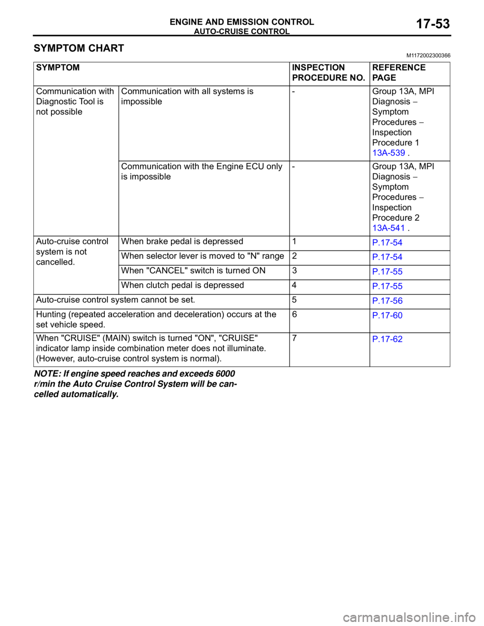
SYMPTOM CHARTM1172002300366
NOTE: If engine speed reaches and exceeds 6000
r/min the Auto Cruise Control System will be can-
celled automatically.SYMPTOM INSPECTION
PROCEDURE NO.REFERENCE
PA G E
Communication with
Diagnostic Tool is
not possibleCommunication with all systems is
impossible- Group 13A, MPI
Diagnosis
Symptom
Procedures
Inspection
Procedure 1
13A-539 .
Communication with the Engine ECU only
is impossible- Group 13A, MPI
Diagnosis
Symptom
Procedures
Inspection
Procedure 2
13A-541 .
Auto-cruise control
system is not
cancelled.When brake pedal is depressed 1
P.17-54
When selector lever is moved to "N" range 2
P.17-54
When "CANCEL" switch is turned ON 3
P.17-55
When clutch pedal is depressed 4
P.17-55
Auto-cruise control system cannot be set. 5
P.17-56
Hunting (repeated acceleration and deceleration) occurs at the
set vehicle speed.6
P.17-60
When "CRUISE" (MAIN) switch is turned "ON", "CRUISE"
indicator lamp inside combination meter does not illuminate.
(However, auto-cruise control system is normal).7
P.17-62
Page 1391 of 1500
AUTO-CRUISE CONTROL
ENGINE AND EMISSION CONTROL17-60
INSPECTION PROCEDURE 6: Hunting (Repeated Acceleration and Deceleration) Occurs at the Set
Vehicle Speed.
.
COMMENT
The output shaft speed sensor signal or the throttle
body is suspected.
.
TROUBLESHOOTING HINTS (THE MOST
LIKELY CAUSES FOR THIS CASE:)
Malfunction of the output shaft speed sensor.
Malfunction of the throttle body.
Malfunction of the Engine ECU.
Malfunction of the A/T ECU.
Circuit drawings
Refer to circuit diagrams GROUP-90
Refer to configuration diagrams GROUP-80
Refer to component locations GROUP-70
DIAGNOSIS
Required Special Tools:
MB991958: Diagnostic Tool (MUT-III Sub Assembly)
MB991824: V.C.I.
MB991827: MUT-III USB Cable
MB991910: MUT-III Main Harness A
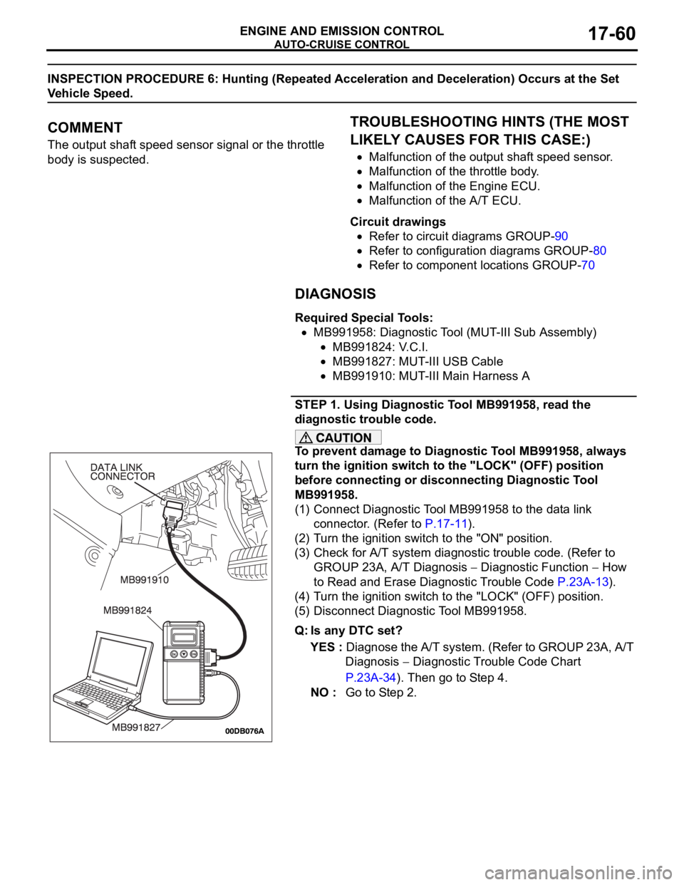
STEP 1. Using Diagnostic Tool MB991958, read the
diagnostic trouble code.
To prevent damage to Diagnostic Tool MB991958, always
turn the ignition switch to the "LOCK" (OFF) position
before connecting or disconnecting Diagnostic Tool
MB991958.
(1) Connect Diagnostic Tool MB991958 to the data link
connector. (Refer to P.17-11).
(2) Turn the ignition switch to the "ON" position.
(3) Check for A/T system diagnostic trouble code. (Refer to
GROUP 23A, A/T Diagnosis
Diagnostic Function How
to Read and Erase Diagnostic Trouble Code P.23A-13).
(4) Turn the ignition switch to the "LOCK" (OFF) position.
(5) Disconnect Diagnostic Tool MB991958.
Q: Is any DTC set?
YES : Diagnose the A/T system. (Refer to GROUP 23A, A/T
Diagnosis
Diagnostic Trouble Code Chart
P.23A-34). Then go to Step 4.
NO : Go to Step 2.
Page 1397 of 1500
AUTO-CRUISE CONTROL
ENGINE AND EMISSION CONTROL17-66
If the air intake duct is removed from the throttle body take great care to keep fingers away
from the throttle plate. The drive motor has very high torque and is capable of random move-
ment at any time. Do not under any circumstances activate the throttle plate by hand.
When removing the throttle body from the intake manifold disconnect the wiring first. During
replacement connect the wiring last.
Do not activate the throttle body using a DC suppy to test the motor,as permanent damage to
the throttle body will result.
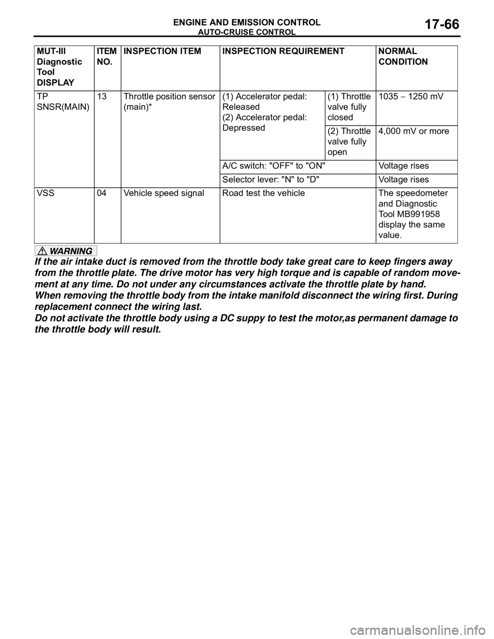
TP
SNSR(MAIN)13 Throttle position sensor
(main)*(1) Accelerator pedal:
Released
(2) Accelerator pedal:
Depressed(1) Throttle
valve fully
closed1035 1250 mV
(2) Throttle
valve fully
open4,000 mV or more
A/C switch: "OFF" to "ON" Voltage rises
Selector lever: "N" to "D" Voltage rises
VSS 04 Vehicle speed signal Road test the vehicle The speedometer
and Diagnostic
Tool MB991958
display the same
value. MUT-III
Diagnostic
To o l
DISPLAYITEM
NO.INSPECTION ITEM INSPECTION REQUIREMENT NORMAL
CONDITION
Page 1400 of 1500
AUTO-CRUISE CONTROL
ENGINE AND EMISSION CONTROL17-69
SPECIAL TOOLSM1172000600509
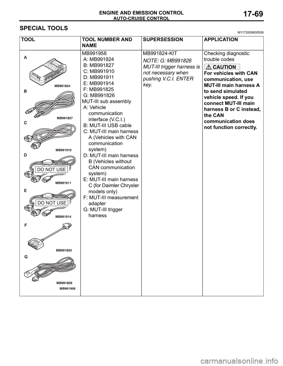
TOOL TOOL NUMBER AND
NAMESUPERSESSION APPLICATION
MB991958
A: MB991824
B: MB991827
C: MB991910
D: MB991911
E: MB991914
F: MB991825
G: MB991826
MUT-III sub assembly
A: Vehicle
communication
interface (V.C.I.)
B: MUT-III USB cable
C: MUT-III main harness
A (Vehicles with CAN
communication
system)
D: MUT-III main harness
B (Vehicles without
CAN communication
system)
E: MUT-III main harness
C (for Daimler Chrysler
models only)
F: MUT-III measurement
adapter
G: MUT-III trigger
harnessMB991824-KIT
NOTE: G: MB991826
MUT-III trigger harness is
not necessary when
pushing V.C.I. ENTER
key.Checking diagnostic
trouble codes
For vehicles with CAN
communication, use
MUT-III main harness A
to send simulated
vehicle speed. If you
connect MUT-III main
harness B or C instead,
the CAN
communication does
not function correctly.
Page 1402 of 1500
AUTO-CRUISE CONTROL
ENGINE AND EMISSION CONTROL17-71
ON-VEHICLE SERVICE
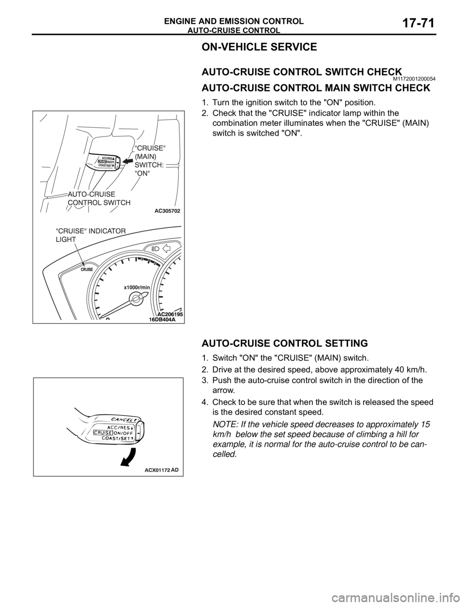
AUTO-CRUISE CONTROL SWITCH CHECKM1172001200054
AUTO-CRUISE CONTROL MAIN SWITCH CHECK
1. Turn the ignition switch to the "ON" position.
2. Check that the "CRUISE" indicator lamp within the
combination meter illuminates when the "CRUISE" (MAIN)
switch is switched "ON".
AUTO-CRUISE CONTROL SETTING
1. Switch "ON" the "CRUISE" (MAIN) switch.
2. Drive at the desired speed, above approximately 40 km/h.
3. Push the auto-cruise control switch in the direction of the
arrow.
4. Check to be sure that when the switch is released the speed
is the desired constant speed.
NOTE: If the vehicle speed decreases to approximately 15
km/h below the set speed because of climbing a hill for
example, it is normal for the auto-cruise control to be can-
celled.
Page 1403 of 1500
AUTO-CRUISE CONTROL
ENGINE AND EMISSION CONTROL17-72
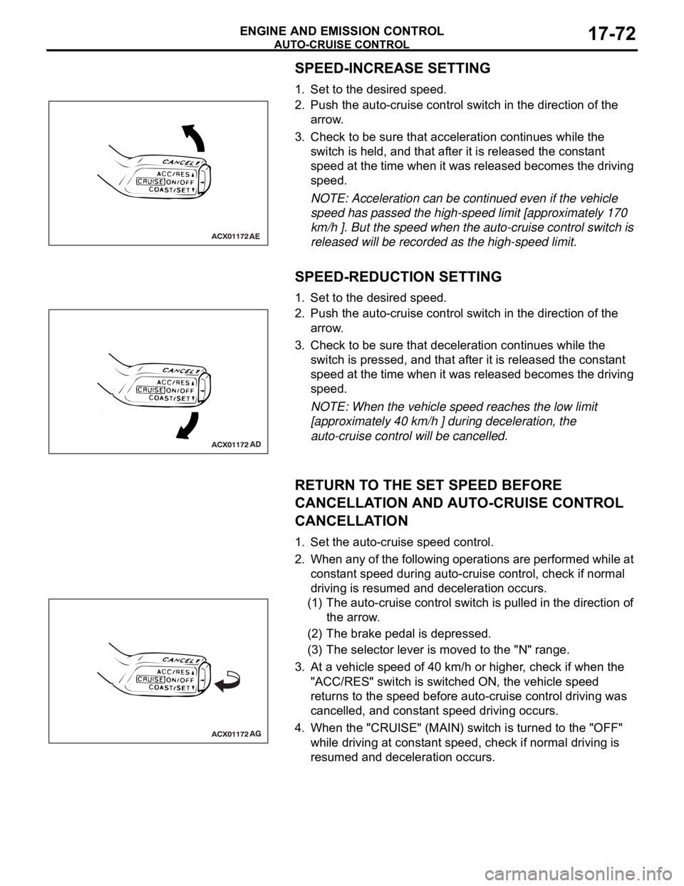
SPEED-INCREASE SETTING
1. Set to the desired speed.
2. Push the auto-cruise control switch in the direction of the
arrow.
3. Check to be sure that acceleration continues while the
switch is held, and that after it is released the constant
speed at the time when it was released becomes the driving
speed.
NOTE: Acceleration can be continued even if the vehicle
speed has passed the high-speed limit [approximately 170
km/h ]. But the speed when the auto-cruise control switch is
released will be recorded as the high-speed limit.
SPEED-REDUCTION SETTING
1. Set to the desired speed.
2. Push the auto-cruise control switch in the direction of the
arrow.
3. Check to be sure that deceleration continues while the
switch is pressed, and that after it is released the constant
speed at the time when it was released becomes the driving
speed.
NOTE: When the vehicle speed reaches the low limit
[approximately 40 km/h ] during deceleration, the
auto-cruise control will be cancelled.
RETURN TO THE SET SPEED BEFORE
CANCELLATION AND AUTO-CRUISE CONTROL
CANCELLATION
1. Set the auto-cruise speed control.
2. When any of the following operations are performed while at
constant speed during auto-cruise control, check if normal
driving is resumed and deceleration occurs.
(1) The auto-cruise control switch is pulled in the direction of
the arrow.
(2) The brake pedal is depressed.
(3) The selector lever is moved to the "N" range.
3. At a vehicle speed of 40 km/h or higher, check if when the
"ACC/RES" switch is switched ON, the vehicle speed
returns to the speed before auto-cruise control driving was
cancelled, and constant speed driving occurs.
4. When the "CRUISE" (MAIN) switch is turned to the "OFF"
while driving at constant speed, check if normal driving is
resumed and deceleration occurs.
Page 1416 of 1500

SPECIFICATIONS
ENGINE AND EMISSION CONTROL17-85
SPECIFICATIONS
FASTENER TIGHTENING SPECIFICATIONSM1173006400324
SERVICE SPECIFICATIONSM1173000300545
ITEM SPECIFICATION
Auto-cruise control system
Lower cover cap bolt 9.0
2.0 Nm (80 17 in-lb)
Steering wheel assembly nut 41
8 Nm (30 6 ft-lb)
Engine control system
Accelerator pedal assembly nut 13
2 Nm ( 111 22 in-lb)
ITEMSSTANDARD VALUE
Engine control system
Curb idle speed r/min 3.8L Engine 680
100
Emission control system
Purge flow cm
3/s (SCFH) [at 80 95C (176 205F) with sudden revving]20 (2.5)
Evaporative emission purge solenoid coil resistance [at 20
C)] 16
Page 1419 of 1500
GENERAL DESCRIPTION
FRONT AXLE26-2
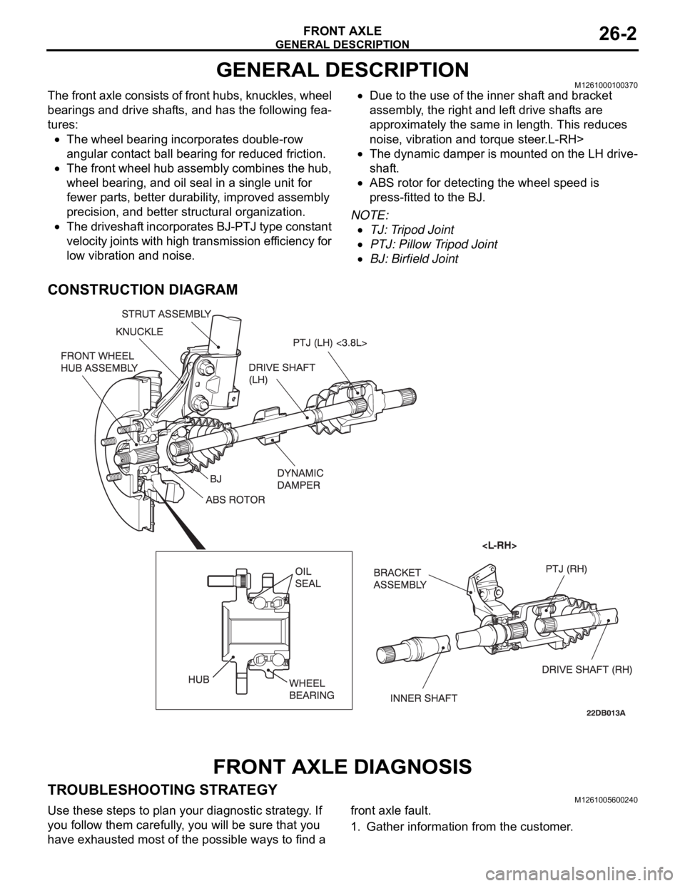
GENERAL DESCRIPTIONM1261000100370
The front axle consists of front hubs, knuckles, wheel
bearings and drive shafts, and has the following fea-
tures:
The wheel bearing incorporates double-row
angular contact ball bearing for reduced friction.
The front wheel hub assembly combines the hub,
wheel bearing, and oil seal in a single unit for
fewer parts, better durability, improved assembly
precision, and better structural organization.
The driveshaft incorporates BJ-PTJ type constant
velocity joints with high transmission efficiency for
low vibration and noise.
Due to the use of the inner shaft and bracket
assembly, the right and left drive shafts are
approximately the same in length. This reduces
noise, vibration and torque steer.L-RH>
The dynamic damper is mounted on the LH drive-
shaft.
ABS rotor for detecting the wheel speed is
press-fitted to the BJ.
NOTE: .
TJ: Tripod Joint
PTJ: Pillow Tripod Joint
BJ: Birfield Joint
CONSTRUCTION DIAGRAM
FRONT AXLE DIAGNOSIS
TROUBLESHOOTING STRATEGYM1261005600240
Use these steps to plan your diagnostic strategy. If
you follow them carefully, you will be sure that you
have exhausted most of the possible ways to find a front axle fault.
1. Gather information from the customer.
Page 1426 of 1500
FRONT AXLE HUB ASSEMBLY
FRONT AXLE26-9
FRONT AXLE HUB ASSEMBLY
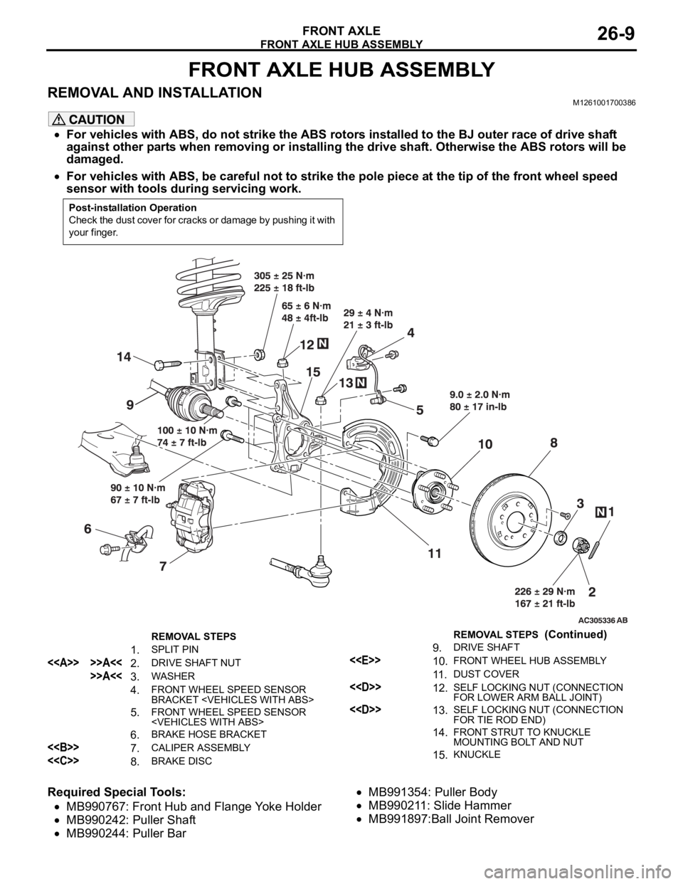
REMOVAL AND INSTALLATIONM1261001700386
For vehicles with ABS, do not strike the ABS rotors installed to the BJ outer race of drive shaft
against other parts when removing or installing the drive shaft. Otherwise the ABS rotors will be
damaged.
For vehicles with ABS, be careful not to strike the pole piece at the tip of the front wheel speed
sensor with tools during servicing work.
Required Special Tools:
MB990767: Front Hub and Flange Yoke Holder
MB990242: Puller Shaft
MB990244: Puller Bar
MB991354: Puller Body
MB990211: Slide Hammer
MB991897:Ball Joint Remover
Post-installation Operation
Check the dust cover for cracks or damage by pushing it with
your finger.
REMOVAL STEPS
1. SPLIT PIN
<> >>A<<2. DRIVE SHAFT NUT
>>A<<3. WASHER
4. FRONT WHEEL SPEED SENSOR
BRACKET
5. FRONT WHEEL SPEED SENSOR
6. BRAKE HOSE BRACKET
<> 7. CALIPER ASSEMBLY
<
9. DRIVE SHAFT
<
11 .DUST COVER
<
FOR LOWER ARM BALL JOINT)
<
FOR TIE ROD END)
14.FRONT STRUT TO KNUCKLE
MOUNTING BOLT AND NUT
15.KNUCKLE
REMOVAL STEPS (Continued)
Page 1430 of 1500
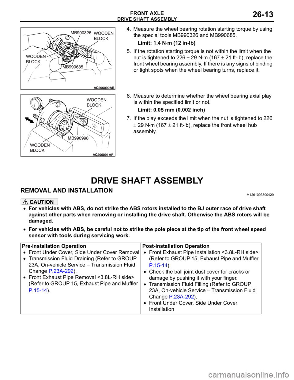
DRIVE SHAFT ASSEMBLY
FRONT AXLE26-13
4. Measure the wheel bearing rotation starting torque by using
the special tools MB990326 and MB990685.
Limit: 1.4 N
m (12 in-lb)
5. If the rotation starting torque is not within the limit when the
nut is tightened to 226
29 Nm (167 21 ft-lb), replace the
front wheel bearing assembly. If there is any signs of binding
or tight spots when the wheel bearing turns, replace it.
6. Measure to determine whether the wheel bearing axial play
is within the specified limit or not.
Limit: 0.05 mm (0.002 inch)
7. If the play exceeds the limit when the nut is tightened to 226
29 Nm (167 21 ft-lb), replace the front wheel hub
assembly.
DRIVE SHAFT ASSEMBLY
REMOVAL AND INSTALLATIONM1261003500429
For vehicles with ABS, do not strike the ABS rotors installed to the BJ outer race of drive shaft
against other parts when removing or installing the drive shaft. Otherwise the ABS rotors will be
damaged.
For vehicles with ABS, be careful not to strike the pole piece at the tip of the front wheel speed
sensor with tools during servicing work.
Pre-installation Operation
Front Under Cover, Side Under Cover Removal
Transmission Fluid Draining (Refer to GROUP
23A, On-vehicle Service
Transmission Fluid
Change P.23A-292).
Front Exhaust Pipe Removal <3.8L-RH side>
(Refer to GROUP 15, Exhaust Pipe and Muffler
P.15-14).Post-installation Operation
Front Exhaust Pipe Installation <3.8L-RH side>
(Refer to GROUP 15, Exhaust Pipe and Muffler
P.15-14).
Check the ball joint dust cover for cracks or
damage by pushing it with your finger.
Transmission Fluid Filling (Refer to GROUP
23A, On-vehicle Service
Transmission Fluid
Change P.23A-292).
Front Under Cover, Side Under Cover
Installation