SPEED MITSUBISHI 380 2005 Manual PDF
[x] Cancel search | Manufacturer: MITSUBISHI, Model Year: 2005, Model line: 380, Model: MITSUBISHI 380 2005Pages: 1500, PDF Size: 47.87 MB
Page 1135 of 1500
KEYLESS ENTRY SYSTEM
BODY42-68
If none of the doors is opened or the ignition key
is not inserted in the ignition switch within 30 sec-
onds after the doors are unlocked using the
transmitter, the ETACS-ECU will relock the doors
automatically. This is called "Timer lock function."
This timer lock function prevents accidental
unlocking of doors. The adjustment function
allows you to change the timer lock period from 30 seconds (default setting) to 60, 120 or 180
seconds. For further details on using the
multi-center display (middle grade type) to adjust
the timer lock period, refer to GROUP 54B,
On-vehicle Service P.54B-486.
NOTE: The timer lock period begins when the doors
are unlocked, and ends when the doors is relocked
automatically.
KEYLESS ENTRY SYSTEM DIAGNOSISBGBCJGAI
The keyless entry system is controlled by the Simpli-
fied Wiring System (SWS). Refer to GROUP 54B,
SWS Diagnosis P.54B-57.
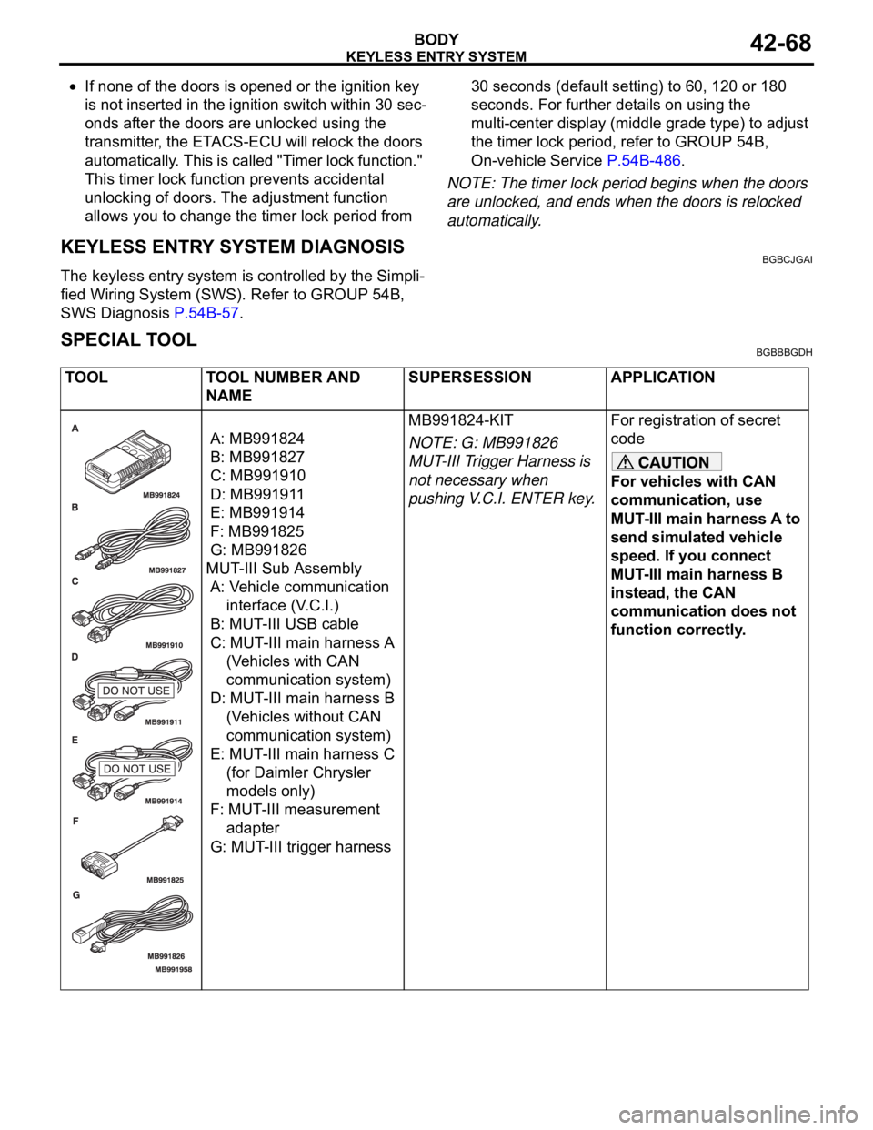
SPECIAL TOOLBGBBBGDH
TOOL TOOL NUMBER AND
NAMESUPERSESSION APPLICATION
A: MB991824
B: MB991827
C: MB991910
D: MB991911
E: MB991914
F: MB991825
G: MB991826
MUT-III Sub Assembly
A: Vehicle communication
interface (V.C.I.)
B: MUT-III USB cable
C: MUT-III main harness A
(Vehicles with CAN
communication system)
D: MUT-III main harness B
(Vehicles without CAN
communication system)
E: MUT-III main harness C
(for Daimler Chrysler
models only)
F: MUT-III measurement
adapter
G: MUT-III trigger harnessMB991824-KIT
NOTE: G: MB991826
MUT-III Trigger Harness is
not necessary when
pushing V.C.I. ENTER key.For registration of secret
code
For vehicles with CAN
communication, use
MUT-III main harness A to
send simulated vehicle
speed. If you connect
MUT-III main harness B
instead, the CAN
communication does not
function correctly.
Page 1212 of 1500
ON-VEHICLE SERVICE
PARKING BRAKES36-5
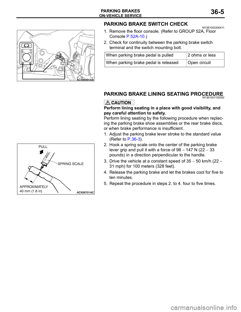
PARKING BRAKE SWITCH CHECKM1361003300411
1. Remove the floor console. (Refer to GROUP 52A, Floor
Console P.52A-10.)
2. Check for continuity between the parking brake switch
terminal and the switch mounting bolt.
PARKING BRAKE LINING SEATING PROCEDUREM1361001100262
Perform lining seating in a place with good visibility, and
pay careful attention to safety.
Perform lining seating by the following procedure when replac-
ing the parking brake shoe assemblies or the rear brake discs,
or when brake performance is insufficient.
1. Adjust the parking brake lever stroke to the standard value
(Refer to P.36-3).
2. Hook a spring scale onto the center of the parking brake
lever grip and pull it with a force of 98
147 N (22 33
pounds) in a direction perpendicular to the handle.
3. Drive the vehicle at a constant speed of 35
50 km/h (22
31 mph) for 100 meters (328 feet).
4. Release the parking brake and let the brakes cool for five to
ten minutes.
5. Repeat the procedure in steps 2. to 4. four to five times.When parking brake pedal is pulled 2 ohms or less
When parking brake pedal is released Open circuit
Page 1216 of 1500
PARKING BRAKE LINING AND DRUM
PARKING BRAKES36-9
REMOVAL SERVICE POINTS
.
<> REAR BRAKE BOLT/REAR BRAKE CALI-
PER ASSEMBLY REMOVAL
Remove the rear brake caliper assembly and support it with
wire or something similar.
.
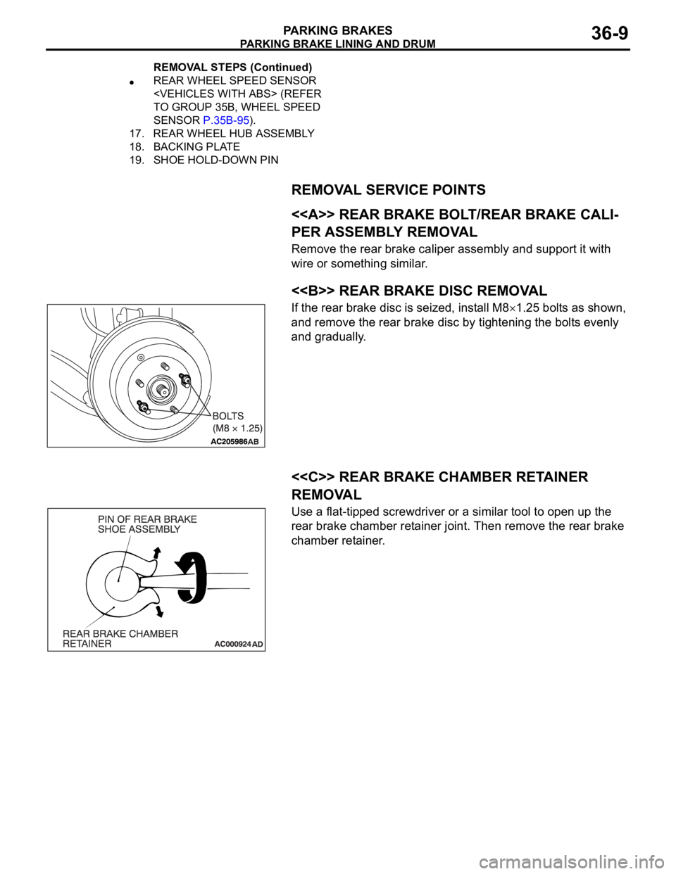
<> REAR BRAKE DISC REMOVAL
If the rear brake disc is seized, install M81.25 bolts as shown,
and remove the rear brake disc by tightening the bolts evenly
and gradually.
.
<
REMOVAL
Use a flat-tipped screwdriver or a similar tool to open up the
rear brake chamber retainer joint. Then remove the rear brake
chamber retainer.
REAR WHEEL SPEED SENSOR
TO GROUP 35B, WHEEL SPEED
SENSOR P.35B-95).
17. REAR WHEEL HUB ASSEMBLY
18. BACKING PLATE
19. SHOE HOLD-DOWN PIN
REMOVAL STEPS (Continued)
Page 1239 of 1500
VEHICLE IDENTIFICATION
GENERAL00-18
VEHICLE IDENTIFICATION
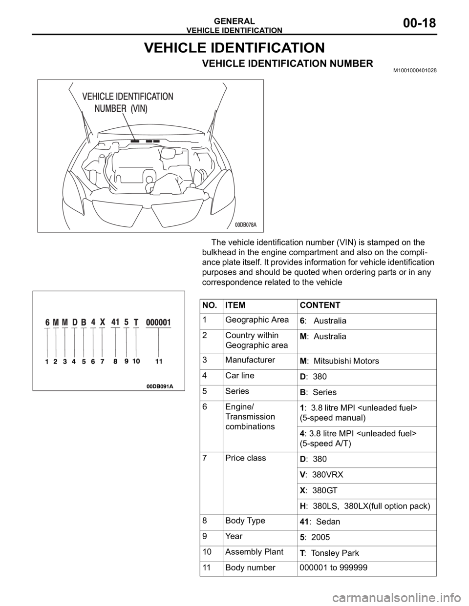
VEHICLE IDENTIFICATION NUMBERM1001000401028
The vehicle identification number (VIN) is stamped on the
bulkhead in the engine compartment and also on the compli-
ance plate itself. It provides information for vehicle identification
purposes and should be quoted when ordering parts or in any
correspondence related to the vehicle
NO. ITEM CONTENT
1 Geographic Area
6: Australia
2 Country within
Geographic areaM: Australia
3 Manufacturer
M: Mitsubishi Motors
4 Car line
D: 380
5Series
B: Series
6 Engine/
Transmission
combinations1: 3.8 litre MPI
(5-speed manual)
4: 3.8 litre MPI
(5-speed A/T)
7Price class
D: 380
V: 380VRX
X: 380GT
H: 380LS, 380LX(full option pack)
8 Body Type
41: Sedan
9Year
5: 2005
10 Assembly Plant
T: Tonsley Park
11 Body number 000001 to 999999
Page 1247 of 1500
TOWING AND HOISTING
GENERAL00-26
TOWING AND HOISTINGM1001000800380
TOWING THE VEHICLE BY A TOW TRUCK
.
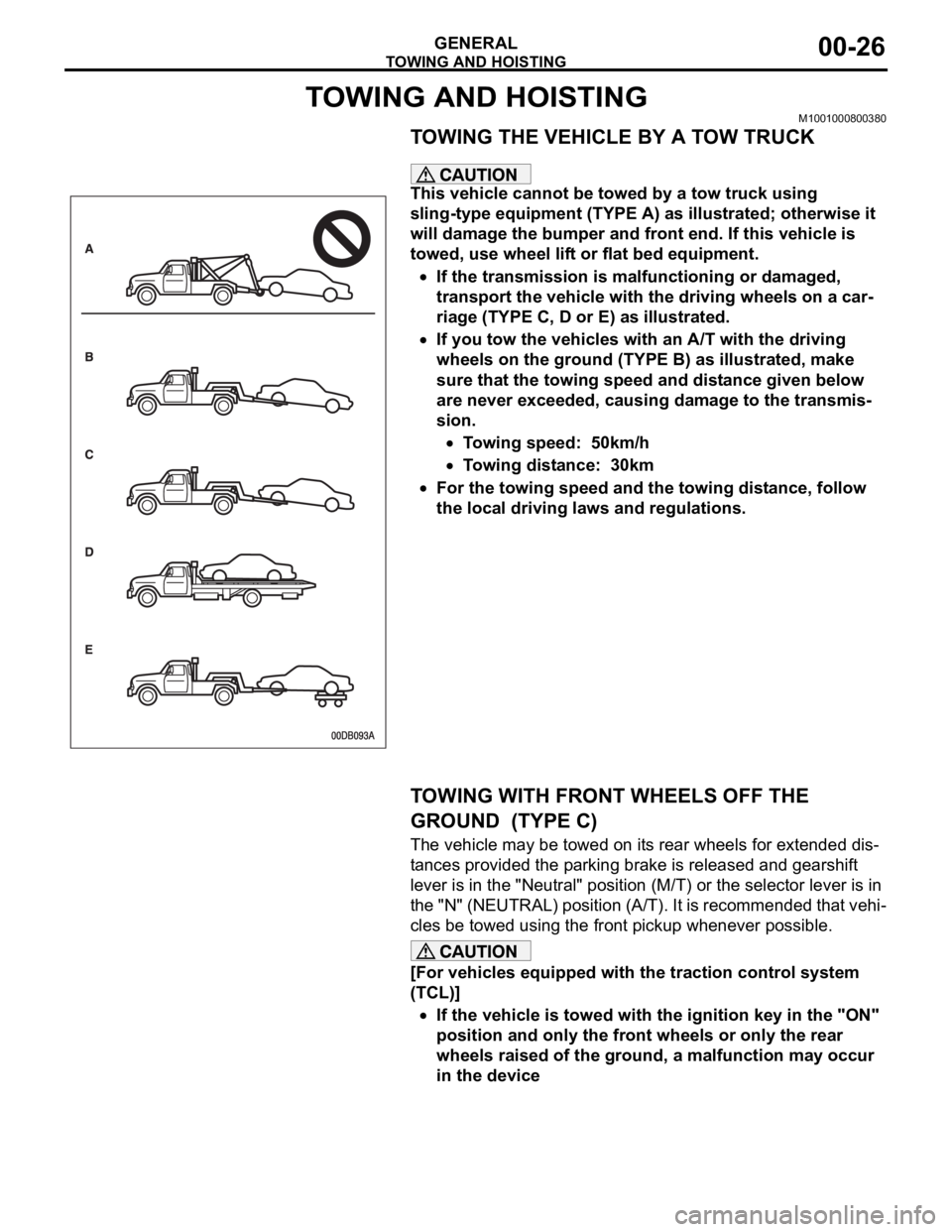
This vehicle cannot be towed by a tow truck using
sling-type equipment (TYPE A) as illustrated; otherwise it
will damage the bumper and front end. If this vehicle is
towed, use wheel lift or flat bed equipment.
If the transmission is malfunctioning or damaged,
transport the vehicle with the driving wheels on a car-
riage (TYPE C, D or E) as illustrated.
If you tow the vehicles with an A/T with the driving
wheels on the ground (TYPE B) as illustrated, make
sure that the towing speed and distance given below
are never exceeded, causing damage to the transmis-
sion.
Towing speed: 50km/h
Towing distance: 30km
For the towing speed and the towing distance, follow
the local driving laws and regulations.
.
TOWING WITH FRONT WHEELS OFF THE
GROUND (TYPE C)
The vehicle may be towed on its rear wheels for extended dis-
tances provided the parking brake is released and gearshift
lever is in the "Neutral" position (M/T) or the selector lever is in
the "N" (NEUTRAL) position (A/T). It is recommended that vehi-
cles be towed using the front pickup whenever possible.
[For vehicles equipped with the traction control system
(TCL)]
If the vehicle is towed with the ignition key in the "ON"
position and only the front wheels or only the rear
wheels raised of the ground, a malfunction may occur
in the device
.
Page 1253 of 1500

TIGHTENING TORQUE
GENERAL00-32
TIGHTENING TORQUEM1001001100555
Each torque value in the table is a standard value for
tightening under the following conditions.
1. Bolts, nuts and washers are all made of steel and
plated with zinc.
2. The threads and bearing surface of bolts and
nuts are all in dry condition.
The values in the table are not applicable:1. If toothed washers are inserted.
2. If plastic parts are fastened.
3. If bolts are tightened to plastic or die-cast
inserted nuts.
4. If self-tapping screws or self-locking nuts are
used.
STANDARD BOLT AND NUT TIGHTENING TORQUE Engine Model No. 6G75
Total displacement 3,828cc
Automatic
TransaxleModel No. F5A5A-4-C2Z
Type 5-speed automatic
Manual
Trans.Model No. F 5M51
Type 5-speed manual
Fuel
systemFuel supply system Electronic controlled multipoint fuel injection (MPI) ITEM 380, 380LS, 380LX 380VRX, 380GT
THREAD SIZE STANDARD TIGHTENING TORQUE
NOMINAL BOLT
DIAMETER (mm)PITCH
(mm)HEAD MARK "4" HEAD MARK "7" HEAD MARK "8"
M5 0.8 2.5
0.5 Nm (23 4
in-lb)5.0 1.0 Nm (44 9
in-lb)6.0 1.0 Nm (53 9
in-lb)
M6 1.0 5.0
1.0 Nm (44 9
in-lb)8.5 1.5 Nm (76 13
in-lb)10 2 Nm (89 17
in-lb)
M8 1.25 11
2 Nm (98 17
in-lb)20 4 Nm (15 3 ft-lb) 24 4 Nm (18 3 ft-lb)
M10 1.25 23
4 Nm (17 3 ft-lb) 42 8 Nm (31 6 ft-lb) 53 7 Nm (39 5 ft-lb)
M12 1.25 42
8 Nm (31 6 ft-lb) 80 10 Nm (59 7
ft-lb)93 12 Nm (68 9
ft-lb)
M14 1.5 70
10 Nm (52 7
ft-lb)130 20 Nm (96 15
ft-lb)150 20 Nm ( 111 14
ft-lb)
M16 1.5 105
15 Nm (78 11
ft-lb)195 25 Nm (144 18
ft-lb)230 30 Nm (170 22
ft-lb)
M18 1.5 150
20 Nm ( 111 14
ft-lb)290 40 Nm (214 29
ft-lb)335 45 Nm (247 33
ft-lb)
Page 1280 of 1500
13C-1
GROUP 13C
TRACTION
CONTROL SYSTEM
(TCL)
CONTENTS
GENERAL DESCRIPTION. . . . . . . . .13C-2
TRACTION CONTROL SYSTEM (TCL)
DIAGNOSIS . . . . . . . . . . . . . . . . . . . .13C-3
INTRODUCTION TO TRACTION CONTROL
SYSTEM (TCL) DIAGNOSIS . . . . . . . . . . . 13C-3
TROUBLESHOOTING STRATEGY . . . . . . 13C-3
DIAGNOSIS FUNCTION. . . . . . . . . . . . . . . 13C-3
DIAGNOSTIC TROUBLE CODE CHART . . 13C-8
DIAGNOSTIC TROUBLE CODE
PROCEDURES . . . . . . . . . . . . . . . . . . . . . . 13C-10
SYMPTOM CHART. . . . . . . . . . . . . . . . . . . 13C-23
SYMPTOM PROCEDURES . . . . . . . . . . . . 13C-23
DATA LIST REFERENCE TABLE . . . . . . . 13C-36
ACTUATOR TEST REFERENCE TABLE. . 13C-37
CHECK AT ABS/TCL-ECU RESISTANCE
AND TERMINAL VOLTAGE . . . . . . . . . . . . 13C-38RESISTANCE AND CONTINUITY
BETWEEN ABS-ECU AND WHEEL SPEED
SENSOR . . . . . . . . . . . . . . . . . . . . . . . . . . . 13C-39
VOLTAGE AND SIGNAL CHECK AT
ABS-ECU USING AN OSCILLOSCOPE . . . 13C-41
SPECIAL TOOLS . . . . . . . . . . . . . . . .13C-45
ON-VEHICLE SERVICE . . . . . . . . . . .13C-47
TCL INDICATOR LIGHT CHECK . . . . . . . . 13C-47
TCL OPERATION CHECK . . . . . . . . . . . . . 13C-47
TCL SWITCH CHECK . . . . . . . . . . . . . . . . . 13C-48
WHEEL SPEED SENSOR CHECK . . . . . . . 13C-48
TCL SWITCH . . . . . . . . . . . . . . . . . . .13C-49
REMOVAL AND INSTALLATION . . . . . . . . 13C-49
WHEEL SPEED SENSOR . . . . . . . . .13C-49
REMOVAL AND INSTALLATION . . . . . . . . 13C-49
ABS/TCL-ECU . . . . . . . . . . . . . . . . . .13C-49
REMOVAL AND INSTALLATION . . . . . . . . 13C-49
Page 1282 of 1500
TRACTION CONTROL SYSTEM (TCL) DIAGNOSIS
TRACTION CONTROL SYSTEM (TCL)13C-3
TRACTION CONTROL SYSTEM (TCL) DIAGNOSIS
INTRODUCTION TO TRACTION CONTROL SYSTEM (TCL) DIAGNOSISM1136004600026
TCL Diagnostic Trouble Code Detection
Conditions
TCL diagnostic trouble codes (TCL DTCs) are set
under different conditions, depending on the mal-
function detected. Most TCL DTCs will only be set
during vehicle operation. Some TCL DTCs will also
be set during the TCL self-check immediately after
the engine is started. When you check if an TCL DTC will be displayed again after the DTC has been
erased, you should recreate the TCL DTC set condi-
tions. Depending on the detection timing and set
conditions for the specific TCL DTC, you must either
drive the vehicle or turn the engine off and restart it.
To set the proper conditions for that DTC again, refer
to "TCL DTC SET CONDITIONS" for each TCL DTC
that you are trying to reset.
TROUBLESHOOTING STRATEGYM1136003100062
Use these steps to plan your diagnostic strategy. If
you follow them carefully, you will check most of the
possible causes of a TCL problem.
1. Gather information from the customer.
2. Verify that the condition described by the
customer exists.
3. Check the vehicle for any TCL DTC. (Refer to
P.13C-3, Diagnosis Function
How to Read and
Erase Diagnostic Trouble Codes).
4. If you can verify the condition but no TCL DTCs
are set, and the malfunction may be intermittent.
(Refer to GROUP 00, How to Use
Troubleshooting/Inspection Service Points
How
to Cope with Intermittent Malfunctions P.00-14).
5. If you can verify the condition but there is no TCL
DTCs, or the system cannot communicate with
diagnostic tool MB991958 (MUT-III sub
assembly), and find the fault. (Refer to P.13C-23,
Symptom Chart).6. If there is a TCL DTC, record the number of the
code, then erase the code from vehicle memory
using the diagnostic tool MB991958 (MUT-III sub
assembly). (Refer to P.13C-3, Diagnosis Function
How to Read and Erase Diagnostic Trouble
Codes).
7. Re-create the TCL DTC set conditions to see if
the same TCL DTC will set again. (Refer to
P.13C-3, Diagnosis Function
How to Read and
Erase Diagnostic Trouble Codes).
If the same TCL DTC sets again, perform the
diagnostic procedures for the set code. (Refer to
P.13C-8, Diagnostic Trouble Code Chart).
NOTE: If the ABS-8 ECU or the active wheel
speed sensor are disconnected, or if the wir-
ing is an open/ short circuit, the ABS 8 ECU
will shut off power supply to the respective
wheel speed sensor. All other wheel speed
sensors will operate normally. To restore the
power supply, the ignition switch must be
turned to the "OFF" position then to the "ON"
position again.
DIAGNOSIS FUNCTIONM1136003200025
HOW TO CONNECT THE DIAGNOSTIC TOOL
(MUT-III)
Required Special Tools:
MB991958: Diagnostic Tool (MUT-III Sub Assembly)
MB991824: Vehicle Communication Interface (V.C.I.)
MB991827: MUT-III USB Cable
MB991910: MUT-III Main Harness A
Page 1287 of 1500
TRACTION CONTROL SYSTEM (TCL) DIAGNOSIS
TRACTION CONTROL SYSTEM (TCL)13C-8
DIAGNOSTIC TROUBLE CODE CHARTM1136003300022
During diagnosis, a DTC associated with other
system may be set when the ignition switch is
turned on with connector(s) disconnected. On
completion, confirm all systems for DTC(s). If
DTC(s) are set, erase them all.
NOTE: If the ABS-8 ECU or the active wheel
speed sensor are disconnected, or if the wiring is
an open/ short circuit, the ABS 8 ECU will shut
off power supply to the respective wheel speed
sensor. All other wheel speed sensors will oper-
ate normally. To restore the power supply, the
ignition switch must be turned to the "OFF" posi-
tion then to the "ON" position again.Follow the inspection chart that is appropriate for the
diagnostic trouble code.
DTC INSPECTION ITEM DIAGNOSTIC CONTENT REFERENCE PAGE
C1200 Front right wheel speed sensor Open circuit or short circuit GROUP 35B, ABS
Diagnosis
Diagnostic Trouble
Code Procedures
C1200 P.35B-10
C1201 Front right wheel speed sensor Abnormal output signal GROUP 35B, ABS
Diagnosis
Diagnostic Trouble
Code Procedures
C1201 P.35B-26
C1205 Front left wheel speed sensor Open circuit or short circuitGROUP 35B, ABS
Diagnosis
Diagnostic Trouble
Code Procedures
C1205 P.35B-10
C1206 Front left wheel speed sensor Abnormal output signal GROUP 35B, ABS
Diagnosis
Diagnostic Trouble
Code Procedures
C1206 P.35B-26
C1210 Rear right wheel speed sensor Open circuit or short circuitGROUP 35B, ABS
Diagnosis
Diagnostic Trouble
Code Procedures
C1210 P.35B-10
C1211 Rear right wheel speed sensor Abnormal output signal GROUP 35B, ABS
Diagnosis
Diagnostic Trouble
Code Procedures
C1211 P.35B-26
C1215 Rear left wheel speed sensor Open circuit or short circuit GROUP 35B, ABS
Diagnosis
Diagnostic Trouble
Code Procedures
C1215 P.35B-10
Page 1288 of 1500

TRACTION CONTROL SYSTEM (TCL) DIAGNOSIS
TRACTION CONTROL SYSTEM (TCL)13C-9
C1216 Rear left wheel speed sensor Abnormal output signal GROUP 35B, ABS
Diagnosis
Diagnostic Trouble
Code Procedures
C1216 P.35B-26
C1225 Deviation between wheel speeds
P.35B-40 or refer to
the above appropriate
abnormal output
sensor signalP.35B-26
C1226* ABS front right solenoid inlet valve -
C1231* ABS front right solenoid outlet valve -
C1236* ABS front left solenoid valve inlet valve -
C1241* ABS front left solenoid valve outlet valve -
C1246* ABS rear right solenoid valve inlet valve -
C1251* ABS rear right solenoid valve outlet valve -
C1256* ABS rear left solenoid valve inlet valve -
C1261* ABS rear left solenoid valve outlet valve -
C1266* ABS hydraulic unit motor stuck -
C1273* ABS hydraulic unit motor drive circuit stuck off -
C1274* ABS hydraulic unit motor drive circuit stuck on -
C1276* ABS valve relay malfunction -
C1278* ABS solenoid valve power circuit stuck off -
C1279* ABS solenoid valve power circuit stuck on -
C1607 ABS/TCL-ECU failure GROUP 35B, ABS
Diagnosis
Diagnostic Trouble
Code Procedures
C1607 P.35B-62
C1640 Variant code value not valid. (TCL only) Incorrect code
programmed into
ABS-ECU. Replace
ABS-ECU modulator.
C1860 ABS/TCL-ECU power supply Abnormal rise in voltage GROUP 35B, ABS
Diagnosis
Diagnostic Trouble
Code Procedures
C1860 P.35B-63
C1861 ABS/TCL-ECU power supply Abnormal drop in voltage GROUP 35B, ABS
Diagnosis
Diagnostic Trouble
Code Procedures
C1861 P.35B-63 DTC INSPECTION ITEM DIAGNOSTIC CONTENT REFERENCE PAGE