display MITSUBISHI 380 2005 Workshop Manual
[x] Cancel search | Manufacturer: MITSUBISHI, Model Year: 2005, Model line: 380, Model: MITSUBISHI 380 2005Pages: 1500, PDF Size: 47.87 MB
Page 424 of 1500

INPUT SIGNAL PROCEDURES
SIMPLIFIED WIRING SYSTEM (SWS)54B-424
STEP 1. Use diagnostic tool MB991958 to select "ECU
COMM Check" on the SWS monitor display.
Check the column-ECU.
To prevent damage to diagnostic tool MB991958, always
turn the ignition switch to the "LOCK" (OFF) position
before connecting or disconnecting diagnostic tool
MB991958. Connect special tool MB991910 before con-
necting special tool MB991812. Be sure to connect special
tool MB991806 after turning on special tool MB991824.
(1) Connect the special tool. Refer to "How to connect SWS
monitor P.54B-13."
(2) Turn the ignition switch to the "ON" position.
(3) Operate the diagnostic tool according to the procedure
below to display "ECU COMM Check."
a. Select "Interactive Diagnosis."
b. Select "System select."
c. Select "SWS."
d. Select "SWS MONITOR."
e. Select "ECU COMM Check."
(4) Diagnostic tool (MUT-III) should show "OK" on the "ECU
COMM Check" menu for the "COLUMN ECU" menu.
Q: Is "OK" displayed for the "COLUMN ECU" menu?
YES : Go to Step 2.
NO : Refer to Inspection Procedure A-2 "Communication
with the column switch (column-ECU) is not possible
P.54B-68."
Page 441 of 1500
INPUT SIGNAL PROCEDURES
SIMPLIFIED WIRING SYSTEM (SWS)54B-441
STEP 1. Check the input signal (by using the pulse check
mode of the monitor).
Check the input signals from the all door switches.
To prevent damage to diagnostic tool MB991958, always
turn the ignition switch to the "LOCK" (OFF) position
before connecting or disconnecting diagnostic tool
MB991958.
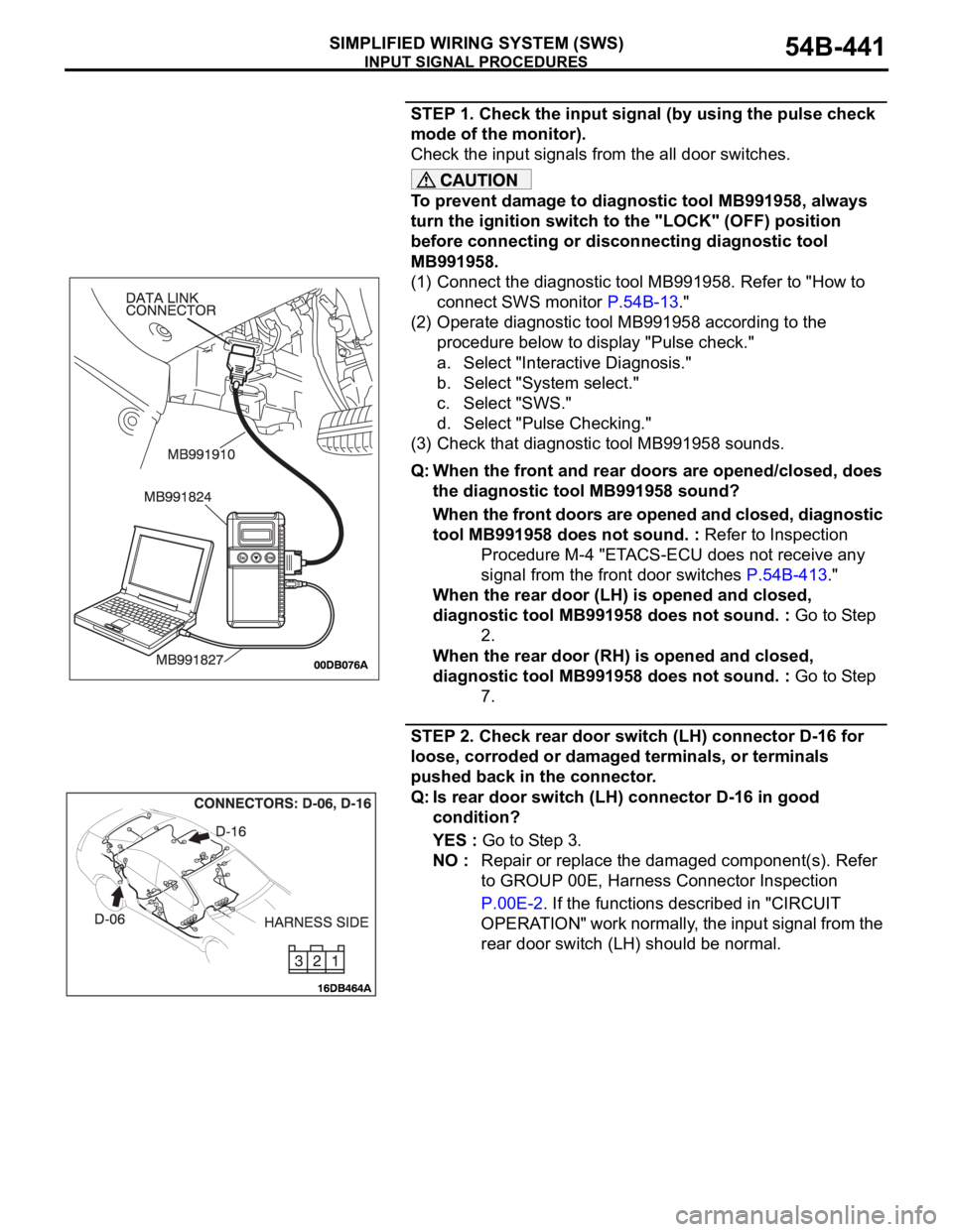
(1) Connect the diagnostic tool MB991958. Refer to "How to
connect SWS monitor P.54B-13."
(2) Operate diagnostic tool MB991958 according to the
procedure below to display "Pulse check."
a. Select "Interactive Diagnosis."
b. Select "System select."
c. Select "SWS."
d. Select "Pulse Checking."
(3) Check that diagnostic tool MB991958 sounds.
Q: When the front and rear doors are opened/closed, does
the diagnostic tool MB991958 sound?
When the front doors are opened and closed, diagnostic
tool MB991958 does not sound. : Refer to Inspection
Procedure M-4 "ETACS-ECU does not receive any
signal from the front door switches P.54B-413."
When the rear door (LH) is opened and closed,
diagnostic tool MB991958 does not sound. : Go to Step
2.
When the rear door (RH) is opened and closed,
diagnostic tool MB991958 does not sound. : Go to Step
7.
STEP 2. Check rear door switch (LH) connector D-16 for
loose, corroded or damaged terminals, or terminals
pushed back in the connector.
Q: Is rear door switch (LH) connector D-16 in good
condition?
YES : Go to Step 3.
NO : Repair or replace the damaged component(s). Refer
to GROUP 00E, Harness Connector Inspection
P.00E-2. If the functions described in "CIRCUIT
OPERATION" work normally, the input signal from the
rear door switch (LH) should be normal.
Page 452 of 1500
INPUT SIGNAL PROCEDURES
SIMPLIFIED WIRING SYSTEM (SWS)54B-452
DIAGNOSIS
Required Special Tools:
MB991223: Harness Set
MB991958: Diagnostic Tool (MUT-III Sub Assembly)
MB991824: Vehicle Communication Interface (V.C.I.)
MB991827: MUT-III USB Cable
MB991910: MUT-III Main Harness A
STEP 1. Check the input signal (by using the pulse check
mode of the monitor).
Check the input signals from the front door lock actuators.
To prevent damage to diagnostic tool MB991958, always
turn the ignition switch to the "LOCK" (OFF) position
before connecting or disconnecting diagnostic tool
MB991958.
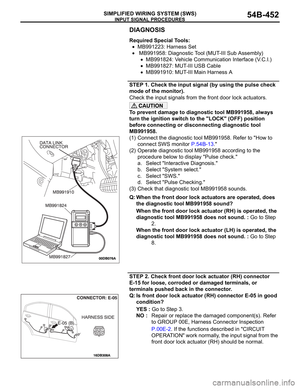
(1) Connect the diagnostic tool MB991958. Refer to "How to
connect SWS monitor P.54B-13."
(2) Operate diagnostic tool MB991958 according to the
procedure below to display "Pulse check."
a. Select "Interactive Diagnosis."
b. Select "System select."
c. Select "SWS."
d. Select "Pulse Checking."
(3) Check that diagnostic tool MB991958 sounds.
Q: When the front door lock actuators are operated, does
the diagnostic tool MB991958 sound?
When the front door lock actuator (RH) is operated, the
diagnostic tool MB991958 does not sound. : Go to Step
2.
When the front door lock actuator (LH) is operated, the
diagnostic tool MB991958 does not sound. : Go to Step
8.
STEP 2. Check front door lock actuator (RH) connector
E-15 for loose, corroded or damaged terminals, or
terminals pushed back in the connector.
Q: Is front door lock actuator (RH) connector E-05 in good
condition?
YES : Go to Step 3.
NO : Repair or replace the damaged component(s). Refer
to GROUP 00E, Harness Connector Inspection
P.00E-2. If the functions described in "CIRCUIT
OPERATION" work normally, the input signal from the
front door lock actuator (RH) should be normal.
Page 461 of 1500
INPUT SIGNAL PROCEDURES
SIMPLIFIED WIRING SYSTEM (SWS)54B-461
DIAGNOSIS
Required Special Tool:
MB991223: Harness Set
MB991958: Diagnostic Tool (MUT-III Sub Assembly)
MB991824: Vehicle Communication Interface (V.C.I.)
MB991827: MUT-III USB Cable
MB991910: MUT-III Main Harness A
STEP 1. Check the input signal (by using the pulse check
mode of the monitor).
Check the input signals from the door lock switch (incorporated
in the power window main switch and front power window sub
switch).
To prevent damage to diagnostic tool MB991958, always
turn the ignition switch to the "LOCK" (OFF) position
before connecting or disconnecting diagnostic tool
MB991958.
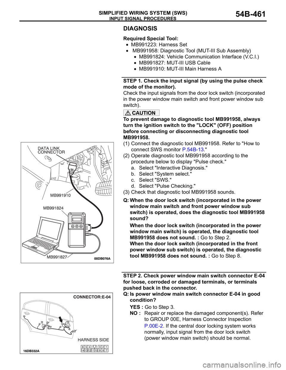
(1) Connect the diagnostic tool MB991958. Refer to "How to
connect SWS monitor P.54B-13."
(2) Operate diagnostic tool MB991958 according to the
procedure below to display "Pulse check."
a. Select "Interactive Diagnosis."
b. Select "System select."
c. Select "SWS."
d. Select "Pulse Checking."
(3) Check that diagnostic tool MB991958 sounds.
Q: When the door lock switch (incorporated in the power
window main switch and front power window sub
switch) is operated, does the diagnostic tool MB991958
sound?
When the door lock switch (incorporated in the power
window main switch) is operated, the diagnostic tool
MB991958 does not sound. : Go to Step 2.
When the door lock switch (incorporated in the front
power window sub switch) is operated, the diagnostic
tool MB991958 does not sound. : Go to Step 8.
STEP 2. Check power window main switch connector E-04
for loose, corroded or damaged terminals, or terminals
pushed back in the connector.
Q: Is power window main switch connector E-04 in good
condition?
YES : Go to Step 3.
NO : Repair or replace the damaged component(s). Refer
to GROUP 00E, Harness Connector Inspection
P.00E-2. If the central door locking system works
normally, input signal from the door lock switch
(power window main switch) should be normal.
Page 486 of 1500

ON-VEHICLE SERVICE
SIMPLIFIED WIRING SYSTEM (SWS)54B-486
ON-VEHICLE SERVICE
CONFIGURATION FUNCTIONM1549002500861
ADJUSTMENT BY OPERATING THE
MULTI CENTER DISPLAY
The following function and system customizations
are possible by using the multi center display.
Page 488 of 1500

ON-VEHICLE SERVICE
SIMPLIFIED WIRING SYSTEM (SWS)54B-488
ITEM (multi-center display) ADJUSTMENT DETAILS
Lamps Headlamp auto-cutout functionThe headlamp automatic shutoff function can
be set in the following ways.
a. Auto-cutout only when the ignition is turned
OFF and drivers side door is open while
lamps are on (default- 1 minute timer)
b. Auto-cutout when ignition is turned OFF
and driver side door is open at any time
(adjustable- 3 minute timer)
c. No auto-cutout (adjustable)
Dome lamp cutout time The interior dimmer delay period can be set in
the following ways.
a. 0 second
b. 15 seconds
c. 30 seconds (default)
d. 60 seconds
e. 120 seconds
f. 180 seconds
Interior lamp auto-cutout time The period before the interior illumination is
turned off automatically can be set in the
following ways.
a. 3 minutes
b. 30 minutes (default)
c. 60 minutes
d. No auto-cutout
Wipers Windshield wiper speed-sensitive
operationThe speed-sensitive wiper function can be
activated or deactivated. (ON by default)
Page 489 of 1500

ON-VEHICLE SERVICE
SIMPLIFIED WIRING SYSTEM (SWS)54B-489
Keyless entry and
power door lock
systemKeyless entry system confirmation
by hornThe horn answerback honking conditions can
be set in the following ways.
a. Horn sounds
b. Horn sounds if doors are already locked
c. Horn does not sound (default)
Keyless entry system confirmation
by turn-signal lampsThe hazard answerback flashing conditions
can be set in the following ways.
a. Locking and unlocking (default)
b. Locking only
c. Unlocking only
d. No indication
Time until automatic relocking after
unlock operation using keyless
entry systemThe timed lock period after unlocking with the
keyless entry transmitter can be set to the
following times.
a. 30 seconds (default)
b. 60 seconds
c. 120 seconds
d. 180 seconds
Unlock operation using keyless
entry system or door keyThe unlocking operations after unlocking with
or without a key can be set in the following
ways.
a. Unlock driver's door on first unlock
operation, and unlock all doors on second
unlock operation (default)
b. Unlock all doors on first unlock operation
Buzzers Turn-signal buzzer The turn-signal buzzer function can be
activated or deactivated. (OFF by default)
Door-ajar warning buzzer The door ajar warning buzzer function can be
activated or deactivated (ON by default).
Default Initialization of above mentioned functions ITEM (multi-center display) ADJUSTMENT DETAILS
Page 495 of 1500
INSTRUMENT PANEL ASSEMBLY
INTERIOR52A-6
6. RADIO AND CD PLAYER,
ASSEMBLY
7. RADIO, CD PLAYER AND CD
CHANGER ASSEMBLY
8. CONSOLE METER HOOD
11. MULTI-CENTER DISPLAY
ASSEMBLY
12. INSTRUMENT DIGITAL CLOCK
ASSEMBLY
13. CENTER CONSOLE ASSEMBLY
14. INSTURMENT PANEL GARNISH
15. COMBINATION METER
ASSEMBLY
FRONT PILLAR TRIM (REFER TO
P.52A-11.)
16. FRONT SPEAKER GARNISH
17. TWEETER
18. INSTRUMENT PANEL SIDE
COVER
19. INSTRUMETN PANEL SIDE AIR
OUTLET
AIR BAG MODULE ASSEMBLY
(DRIVER’S SIDE) (REFER TO
GROUP 52B, AIR BAG MODULE
AND CLOCK SPRING P.52B-237.)
STEERING WHEEL ASSEMBLY
(REFER TO GROUP 37,
STEERING WHEEL P.37-23.)
20. STEERING COLUMN COVERREMOVAL STEPS (Continued)
<>CLOCK SPRING CONNECTOR
<>COLUMN SWITHC CONNECTOR
CLOCK SPRING AND COLUMN
SWITCH ASSEMBLY (REFER TO
GROUP 37, STEERING SHAFT
P.37-25.)
21. INTERIOR TEMPERATURE
SENSOR (GROUP 55B,
SENSORS 55-160.)
22. INSTRUMENT PANEL FRONT
END GARNISH
23. PHOTO SENSOR (GROUP 55B,
SENSORS 55-160.) AND
SECURITY LED.
FLOOR CONSOLE ASSEMBLY
(REFER TO P.52A-10.)
COWL SIDE TRIM (REFER TO
P.52A-11.)
<>AIR BAG MODULE CONNECTOR
(PASSENGER’S SIDE) (REFER
TO GROUP 52B, AIR BAG
MODULE AND CLOCK SPRING
P.52B-237.)
25. INSTRUMENT PANEL ASSEMBLYREMOVAL STEPS (Continued)
Page 520 of 1500
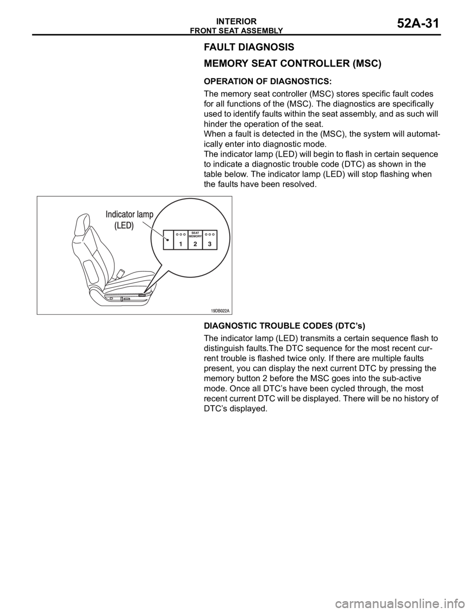
FRONT SEAT ASSEMBLY
INTERIOR52A-31
FAULT DIAGNOSIS
MEMORY SEAT CONTROLLER (MSC)
OPERATION OF DIAGNOSTICS:
The memory seat controller (MSC) stores specific fault codes
for all functions of the (MSC). The diagnostics are specifically
used to identify faults within the seat assembly, and as such will
hinder the operation of the seat.
When a fault is detected in the (MSC), the system will automat-
ically enter into diagnostic mode.
The indicator lamp (LED) will begin to flash in certain sequence
to indicate a diagnostic trouble code (DTC) as shown in the
table below. The indicator lamp (LED) will stop flashing when
the faults have been resolved.
DIAGNOSTIC TROUBLE CODES (DTC’s)
The indicator lamp (LED) transmits a certain sequence flash to
distinguish faults.The DTC sequence for the most recent cur-
rent trouble is flashed twice only. If there are multiple faults
present, you can display the next current DTC by pressing the
memory button 2 before the MSC goes into the sub-active
mode. Once all DTC’s have been cycled through, the most
recent current DTC will be displayed. There will be no history of
DTC’s displayed.
Page 559 of 1500
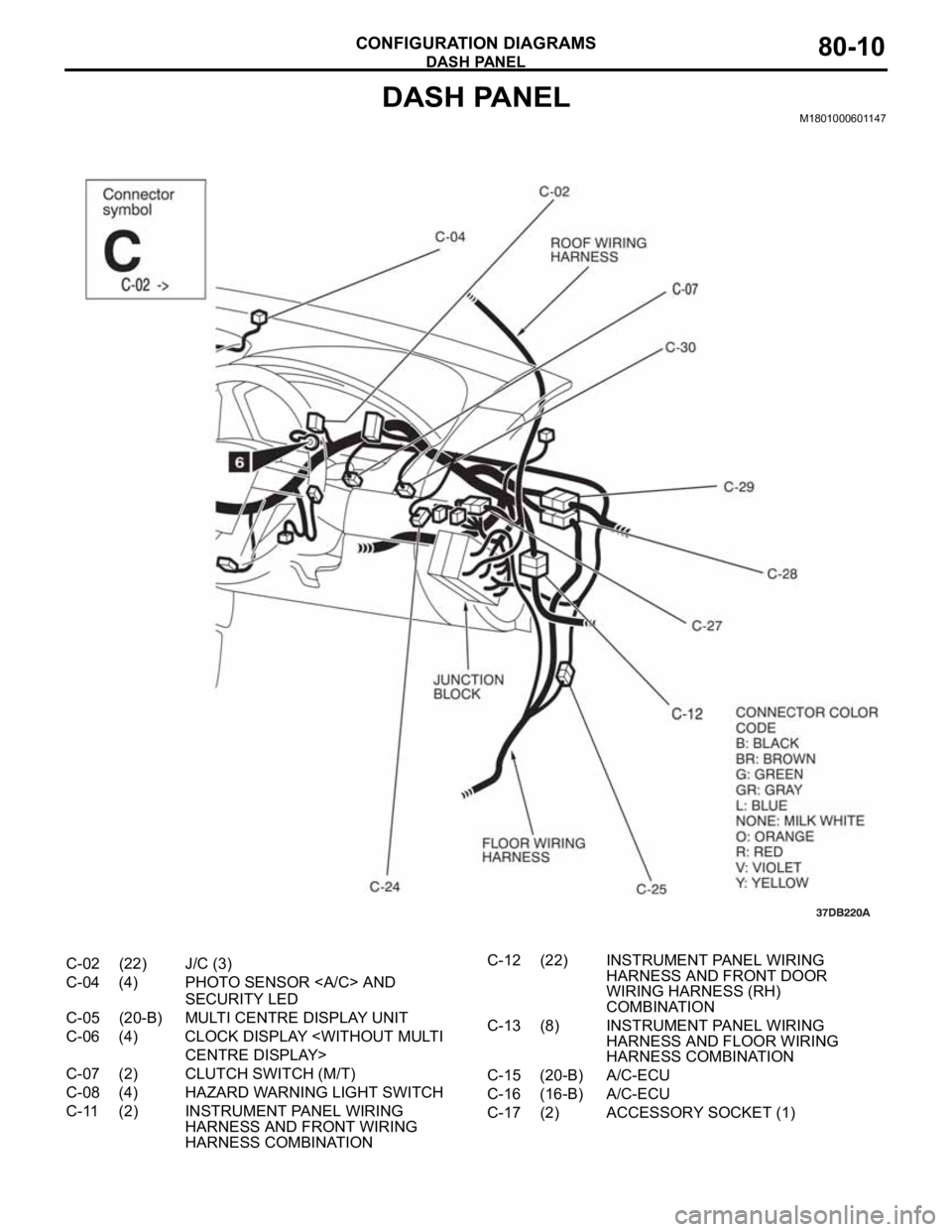
DASH PANEL
CONFIGURATION DIAGRAMS80-10
DASH PANELM1801000601147
C-02 (22) J/C (3)
C-04 (4) PHOTO SENSOR AND
SECURITY LED
C-05 (20-B) MULTI CENTRE DISPLAY UNIT
C-06 (4) CLOCK DISPLAY
C-07 (2) CLUTCH SWITCH (M/T)
C-08 (4) HAZARD WARNING LIGHT SWITCH
C-11 (2) INSTRUMENT PANEL WIRING
HARNESS AND FRONT WIRING
HARNESS COMBINATIONC-12 (22) INSTRUMENT PANEL WIRING
HARNESS AND FRONT DOOR
WIRING HARNESS (RH)
COMBINATION
C-13 (8) INSTRUMENT PANEL WIRING
HARNESS AND FLOOR WIRING
HARNESS COMBINATION
C-15 (20-B) A/C-ECU
C-16 (16-B) A/C-ECU
C-17 (2) ACCESSORY SOCKET (1)