display MITSUBISHI 380 2005 Workshop Manual
[x] Cancel search | Manufacturer: MITSUBISHI, Model Year: 2005, Model line: 380, Model: MITSUBISHI 380 2005Pages: 1500, PDF Size: 47.87 MB
Page 579 of 1500
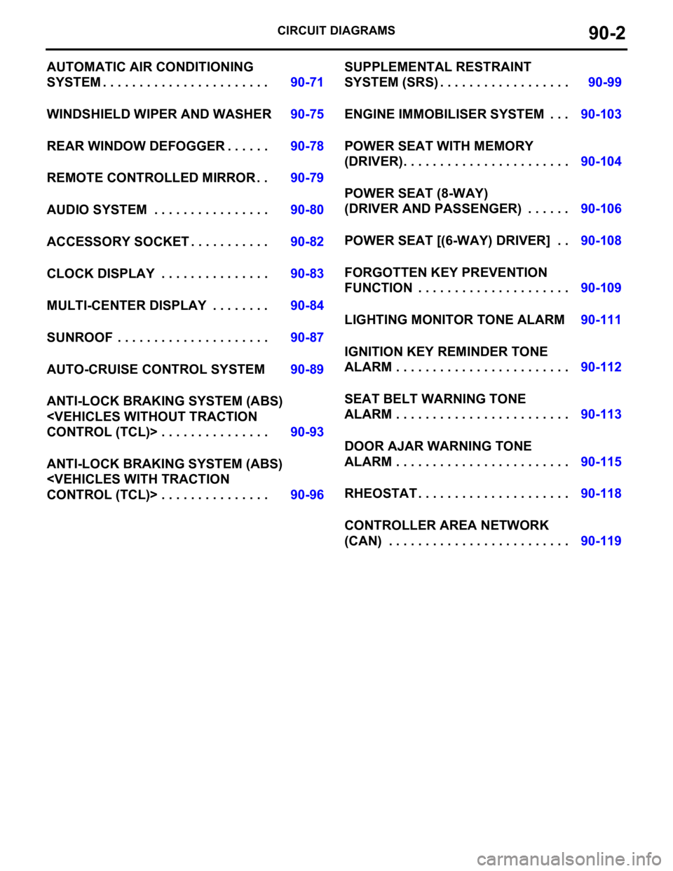
CIRCUIT DIAGRAMS90-2
AUTOMATIC AIR CONDITIONING
SYSTEM . . . . . . . . . . . . . . . . . . . . . . .90-71
WINDSHIELD WIPER AND WASHER90-75
REAR WINDOW DEFOGGER . . . . . .90-78
REMOTE CONTROLLED MIRROR . .90-79
AUDIO SYSTEM . . . . . . . . . . . . . . . .90-80
ACCESSORY SOCKET . . . . . . . . . . .90-82
CLOCK DISPLAY . . . . . . . . . . . . . . .90-83
MULTI-CENTER DISPLAY . . . . . . . .90-84
SUNROOF . . . . . . . . . . . . . . . . . . . . .90-87
AUTO-CRUISE CONTROL SYSTEM90-89
ANTI-LOCK BRAKING SYSTEM (ABS)
ANTI-LOCK BRAKING SYSTEM (ABS)
SYSTEM (SRS) . . . . . . . . . . . . . . . . . .90-99
ENGINE IMMOBILISER SYSTEM . . .90-103
POWER SEAT WITH MEMORY
(DRIVER). . . . . . . . . . . . . . . . . . . . . . .90-104
POWER SEAT (8-WAY)
(DRIVER AND PASSENGER) . . . . . .90-106
POWER SEAT [(6-WAY) DRIVER] . .90-108
FORGOTTEN KEY PREVENTION
FUNCTION . . . . . . . . . . . . . . . . . . . . .90-109
LIGHTING MONITOR TONE ALARM90-111
IGNITION KEY REMINDER TONE
ALARM . . . . . . . . . . . . . . . . . . . . . . . .90-112
SEAT BELT WARNING TONE
ALARM . . . . . . . . . . . . . . . . . . . . . . . .90-113
DOOR AJAR WARNING TONE
ALARM . . . . . . . . . . . . . . . . . . . . . . . .90-115
RHEOSTAT . . . . . . . . . . . . . . . . . . . . .90-118
CONTROLLER AREA NETWORK
(CAN) . . . . . . . . . . . . . . . . . . . . . . . . .90-119
Page 590 of 1500

CENTRALISED JUNCTION
CIRCUIT DIAGRAMS90-13
19 Front-ECU (Field
effect transistor for
headlamp: Low)Fuse 10 Red Headlamp (LH) and headlamp (Low:
LH)
20 Front-ECU (Taillamp
relay)7.5 Brown A/C-ECU, A/T selector lever position
illumination lamp, combination meter,
fog lamp switch, headlamp (RH),
glove box lamp, hazard warning lamp
switch, multi-center display unit,
radio, CD player, rear combination
lamp (RH), rheostat and TCL switch
21 7.5 Brown Headlamp (LH), license plate lamp
and rear combination lamp (LH)
22 Battery/Alternator
(Fusible link No.27)15 Blue A/C-ECU, column switch,
combination meter, ETACS-ECU,
front-ECU, key reminder switch, multi-
center display unit, radio, CD player,
and vanity mirror lamp
23 Ignition switch (ACC) 10 Red A/C-ECU, accessory socket relay,
ETACS-ECU, multi-center display
unit, radio, CD player.
24 Battery/Alternator
(Fusible link No.27)15 Blue Fuel pump module
25 Ignition switch (ACC) 30 Green Front-ECU and windshield wiper
motor
26 Battery/Alternator
(Fusible link No.27)Fusible
link20 Light blue Anti-lock braking system(solenoid
valve)
27
Alternator120
Battery, front-ECU, fusible link Nos.1,
2, 3, 4, 5 and 26 and fuse Nos.6, 7, 8,
9, 10, 11, 13, 14, 15, 22 and 24 (in
relay box) NO. POWER SUPPLY
CIRCUITNAME RATED
CAPACITY (A)HOUSING
COLOURLOAD CIRCUIT
Page 592 of 1500

CENTRALISED JUNCTION
CIRCUIT DIAGRAMS90-15
NO. POWER SUPPLY
CIRCUITNAME RATED
CAPACITY (A)HOUSING
COLOURLOAD CIRCUIT
1 Fusible link No.1 Fuse 30 Green Rear window demister
2 30 Green Blower motor and resistor
3
4
5 15 Blue Accessory socket
6 15 Blue Data link connector and ETACS-ECU
7 Ignition switch (ACC) 15 Blue ETACS-ECU
8
9 Ignition switch (IG2) 7.5 Brown Sunroof assembly
10 Ignition switch (ACC) 7.5 Brown Remote controlled mirror
11
12
13 Ignition switch (IG1) 7.5 Brown Fuel pump relay and Engine ECU
14 Ignition switch (ACC) 20 Yellow Windscreen wiper
15 Fusible link No.1
(Fuse No.5 in junction
block)7.5 Brown Remote controlled mirror
16 Ignition switch (IG2) 7.5 Brown A/C compressor clutch relay,
A/C-ECU, blower relay, condenser
fan motor, fan control relay,
front-ECU, outside/inside air selection
damper control motor and rear
window defogger relay
17 Ignition switch (IG1)
18 7.5 Brown A/T control relay, input shaft speed
sensor, output shaft speed sensor,
Engine ECU, rear combination lamp
and SRS-ECU
19 7.5 Brown ABS-ECU, ABS/TCL-ECU, column
switch, combination meter,
ETACS-ECU, multi-center display unit
and SRS-ECU
20 10 Red Ignition coil
21
22
23 Fusible link No.5 20 Yellow Sunroof assembly
24
Page 660 of 1500
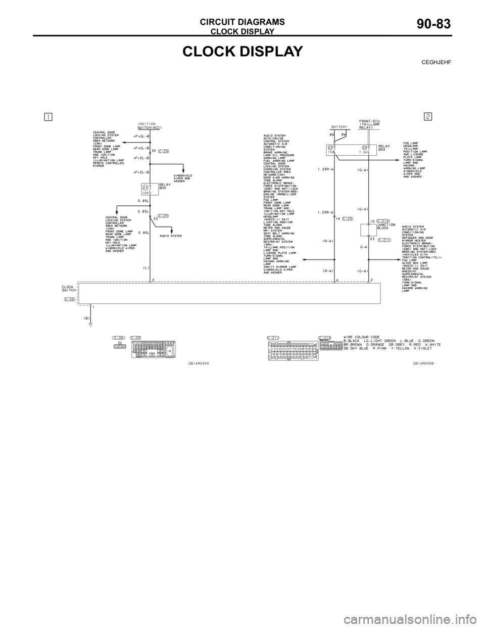
CLOCK DISPLAY
CIRCUIT DIAGRAMS90-83
CLOCK DISPLAYCEGHJEHF
Page 661 of 1500
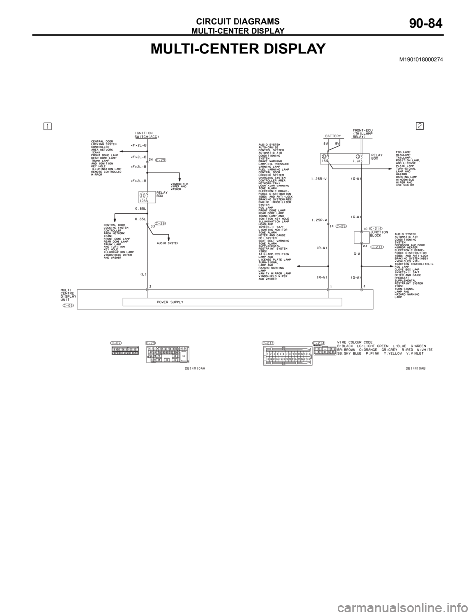
MULTI-CENTER DISPLAY
CIRCUIT DIAGRAMS90-84
MULTI-CENTER DISPLAYM1901018000274
Page 662 of 1500
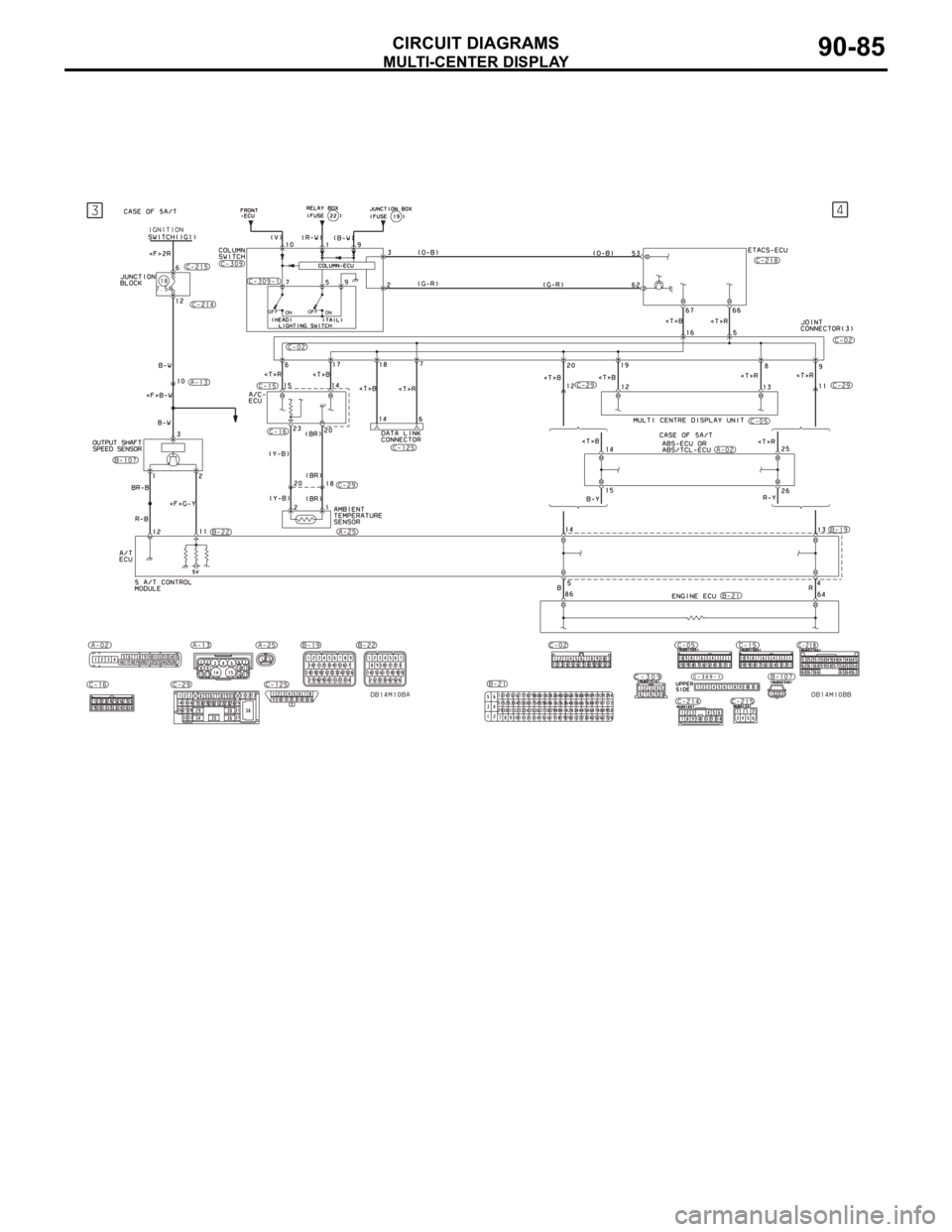
MULTI-CENTER DISPLAY
CIRCUIT DIAGRAMS90-85
Page 663 of 1500

MULTI-CENTER DISPLAY
CIRCUIT DIAGRAMS90-86
MULTI-CENTER DISPLAY (CONTINUED)
Page 709 of 1500
AUTO A/C DIAGNOSIS
HEATER, AIR CONDITIONING AND VENTILATION55-8
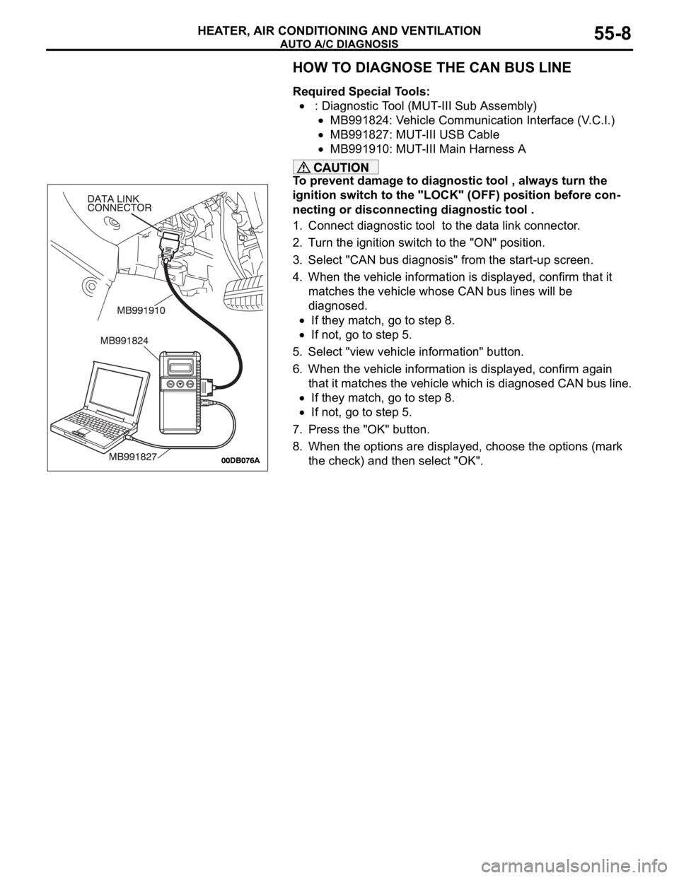
HOW TO DIAGNOSE THE CAN BUS LINE
Required Special Tools:
: Diagnostic Tool (MUT-III Sub Assembly)
MB991824: Vehicle Communication Interface (V.C.I.)
MB991827: MUT-III USB Cable
MB991910: MUT-III Main Harness A
To prevent damage to diagnostic tool , always turn the
ignition switch to the "LOCK" (OFF) position before con-
necting or disconnecting diagnostic tool .
1. Connect diagnostic tool to the data link connector.
2. Turn the ignition switch to the "ON" position.
3. Select "CAN bus diagnosis" from the start-up screen.
4. When the vehicle information is displayed, confirm that it
matches the vehicle whose CAN bus lines will be
diagnosed.
If they match, go to step 8.
If not, go to step 5.
5. Select "view vehicle information" button.
6. When the vehicle information is displayed, confirm again
that it matches the vehicle which is diagnosed CAN bus line.
If they match, go to step 8.
If not, go to step 5.
7. Press the "OK" button.
8. When the options are displayed, choose the options (mark
the check) and then select "OK".
Page 713 of 1500
AUTO A/C DIAGNOSIS
HEATER, AIR CONDITIONING AND VENTILATION55-12
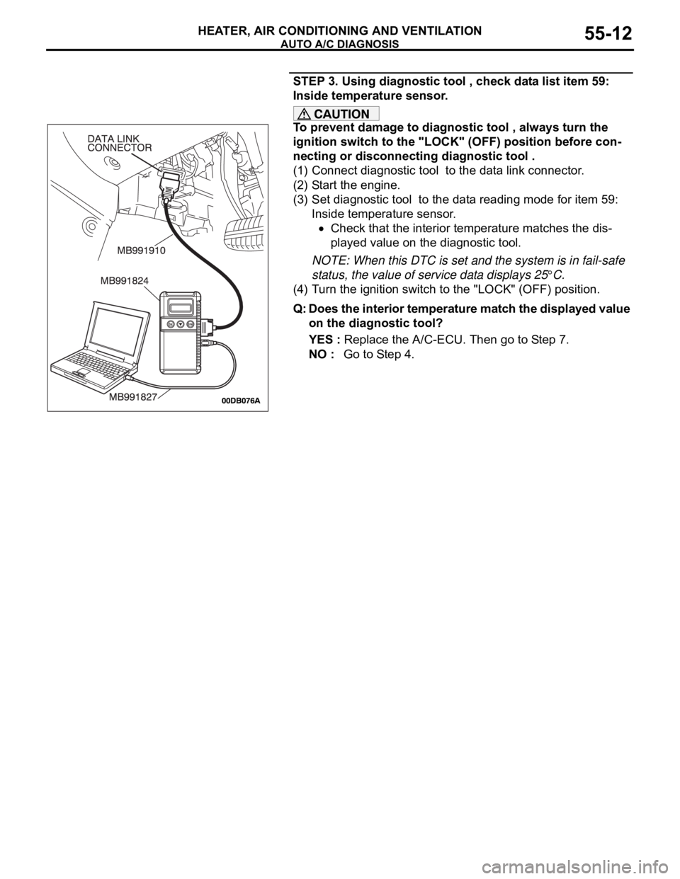
STEP 3. Using diagnostic tool , check data list item 59:
Inside temperature sensor.
To prevent damage to diagnostic tool , always turn the
ignition switch to the "LOCK" (OFF) position before con-
necting or disconnecting diagnostic tool .
(1) Connect diagnostic tool to the data link connector.
(2) Start the engine.
(3) Set diagnostic tool to the data reading mode for item 59:
Inside temperature sensor.
Check that the interior temperature matches the dis-
played value on the diagnostic tool.
NOTE: When this DTC is set and the system is in fail-safe
status, the value of service data displays 25
C.
(4) Turn the ignition switch to the "LOCK" (OFF) position.
Q: Does the interior temperature match the displayed value
on the diagnostic tool?
YES : Replace the A/C-ECU. Then go to Step 7.
NO : Go to Step 4.
Page 719 of 1500
AUTO A/C DIAGNOSIS
HEATER, AIR CONDITIONING AND VENTILATION55-18
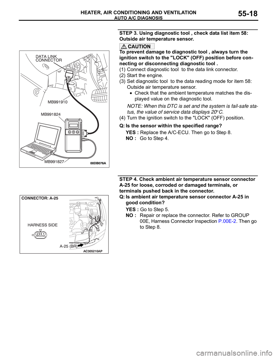
STEP 3. Using diagnostic tool , check data list item 58:
Outside air temperature sensor.
To prevent damage to diagnostic tool , always turn the
ignition switch to the "LOCK" (OFF) position before con-
necting or disconnecting diagnostic tool .
(1) Connect diagnostic tool to the data link connector.
(2) Start the engine.
(3) Set diagnostic tool to the data reading mode for item 58:
Outside air temperature sensor.
Check that the ambient temperature matches the dis-
played value on the diagnostic tool.
NOTE: When this DTC is set and the system is fail-safe sta-
tus, the value of service data displays 20
C.
(4) Turn the ignition switch to the "LOCK" (OFF) position.
Q: Is the sensor within the specified range?
YES : Replace the A/C-ECU. Then go to Step 8.
NO : Go to Step 4.
STEP 4. Check ambient air temperature sensor connector
A-25 for loose, corroded or damaged terminals, or
terminals pushed back in the connector.
Q: Is ambient air temperature sensor connector A-25 in
good condition?
YES : Go to Step 5.
NO : Repair or replace the connector. Refer to GROUP
00E, Harness Connector Inspection P.00E-2. Then go
to Step 8.