display MITSUBISHI 380 2005 Workshop Manual
[x] Cancel search | Manufacturer: MITSUBISHI, Model Year: 2005, Model line: 380, Model: MITSUBISHI 380 2005Pages: 1500, PDF Size: 47.87 MB
Page 1135 of 1500
KEYLESS ENTRY SYSTEM
BODY42-68
If none of the doors is opened or the ignition key
is not inserted in the ignition switch within 30 sec-
onds after the doors are unlocked using the
transmitter, the ETACS-ECU will relock the doors
automatically. This is called "Timer lock function."
This timer lock function prevents accidental
unlocking of doors. The adjustment function
allows you to change the timer lock period from 30 seconds (default setting) to 60, 120 or 180
seconds. For further details on using the
multi-center display (middle grade type) to adjust
the timer lock period, refer to GROUP 54B,
On-vehicle Service P.54B-486.
NOTE: The timer lock period begins when the doors
are unlocked, and ends when the doors is relocked
automatically.
KEYLESS ENTRY SYSTEM DIAGNOSISBGBCJGAI
The keyless entry system is controlled by the Simpli-
fied Wiring System (SWS). Refer to GROUP 54B,
SWS Diagnosis P.54B-57.
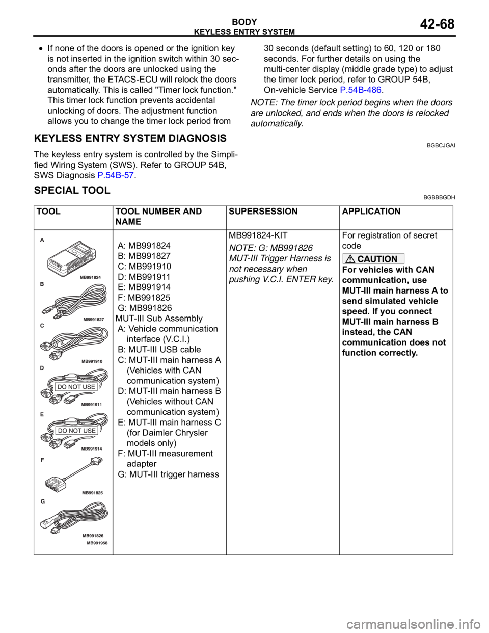
SPECIAL TOOLBGBBBGDH
TOOL TOOL NUMBER AND
NAMESUPERSESSION APPLICATION
A: MB991824
B: MB991827
C: MB991910
D: MB991911
E: MB991914
F: MB991825
G: MB991826
MUT-III Sub Assembly
A: Vehicle communication
interface (V.C.I.)
B: MUT-III USB cable
C: MUT-III main harness A
(Vehicles with CAN
communication system)
D: MUT-III main harness B
(Vehicles without CAN
communication system)
E: MUT-III main harness C
(for Daimler Chrysler
models only)
F: MUT-III measurement
adapter
G: MUT-III trigger harnessMB991824-KIT
NOTE: G: MB991826
MUT-III Trigger Harness is
not necessary when
pushing V.C.I. ENTER key.For registration of secret
code
For vehicles with CAN
communication, use
MUT-III main harness A to
send simulated vehicle
speed. If you connect
MUT-III main harness B
instead, the CAN
communication does not
function correctly.
Page 1228 of 1500
HOW TO USE TROUBLESHOOTING/INSPECTION SERVICE POINTS
GENERAL00-7
HOW TO USE TROUBLESHOOTING/INSPECTION SERVICE
POINTS
TROUBLESHOOTING CONTENTSM1001013300062
During diagnosis, a DTC code associated with
other system may be set when the ignition
switch is turned on with connector(s) discon-
nected. On completion, confirm all systems
for DTC code(s). If DTC code(s) are set, erase
them all.
When the DIAGNOSTIC TOOL (MUT-III)
detects a diagnostic trouble code, its display
informs users whether a mechanical problem
currently exists (“current trouble”) or whether
it existed before but normal operation has
been restored (“past trouble”). However, if an
MPI, TPMS or SRS airbag-related DTC is set,
“Active DTC/Stored DTC” is not displayed. In
this case, follow the diagnosis procedure for
current trouble.
If a trouble, detected in a CAN communica-
tion-capable system, can be reproduced,
diagnose the CAN bus lines (Refer to GROUP
54C, Can Bus Line Diagnostics Chart
P.54C-15 or P.54C-15).
Troubleshooting of electronic control systems for
which the MUT -III can be used follows the basic out-
line described below. Even in systems for which the
MUT-III cannot be used, part of these systems still
follow this outline.
1. STANDARD FLOW OF DIAGNOSTIC
TROUBLESHOOTING
Troubleshooting strategy is shown in each group.
2. SYSTEM OPERATION AND SYMPTOM
VERIFICATION TESTS
If verification of the symptom(s) is difficult, proce-
dures for checking operation and verifying symptoms
are shown.
3. DIAGNOSTIC FUNCTION
The following trouble code diagnoses are shown.
How to read diagnostic trouble codes
How to erase diagnostic trouble codes
Input inspection service points
4. DIAGNOSTIC TROUBLE CODE CHART
If the MUT-III displays a diagnostic trouble code, find
the applicable inspection procedure according to this
chart.
5. SYMPTOM CHART
If there are symptoms, even though the MUT-III
shows that no DTCs are set, inspection procedures
for each symptom will be found by using this chart.
6. DIAGNOSTIC TROUBLE CODE
PROCEDURES
Indicates the inspection procedures corresponding to
each diagnostic trouble code. (Refer to P.00-9).
7. SYMPTOM PROCEDURES
Indicates the inspection procedures corresponding to
each symptom listed in the Symptom Chart (Refer to
P.00-9).
8. SERVICE DATA REFERENCE TABLE
Inspection items and normal judgment values have
been provided in this chart as reference information.
9. CHECK AT ECU TERMINALS
Terminal numbers for the ECU connectors, inspec-
tion items, and standard values have been provided
in this chart as reference information.
.
TERMINAL VOLTAGE CHECKS
1. Use correct tool to check each pin location on the
ENGINE-ECU Check harnes MB992044 and
measure with voltmeter.
Short-circuiting the positive (+) test probe
between a connector terminal and ground could
damage the vehicle wiring, the sensor, the ECU,
or all three. Use care to prevent this!
2. Insert the correct terminal tool into each of the
ENGINE-ECU check harness connector
terminals, and measure the voltage while referring
to the check chart.
NOTE: Measure voltage with the ECU connectors
connected.
You may find it convenient to pull out the ECU to
make it easier to connect the ENGINE-ECU check
harness.
Page 1282 of 1500
TRACTION CONTROL SYSTEM (TCL) DIAGNOSIS
TRACTION CONTROL SYSTEM (TCL)13C-3
TRACTION CONTROL SYSTEM (TCL) DIAGNOSIS
INTRODUCTION TO TRACTION CONTROL SYSTEM (TCL) DIAGNOSISM1136004600026
TCL Diagnostic Trouble Code Detection
Conditions
TCL diagnostic trouble codes (TCL DTCs) are set
under different conditions, depending on the mal-
function detected. Most TCL DTCs will only be set
during vehicle operation. Some TCL DTCs will also
be set during the TCL self-check immediately after
the engine is started. When you check if an TCL DTC will be displayed again after the DTC has been
erased, you should recreate the TCL DTC set condi-
tions. Depending on the detection timing and set
conditions for the specific TCL DTC, you must either
drive the vehicle or turn the engine off and restart it.
To set the proper conditions for that DTC again, refer
to "TCL DTC SET CONDITIONS" for each TCL DTC
that you are trying to reset.
TROUBLESHOOTING STRATEGYM1136003100062
Use these steps to plan your diagnostic strategy. If
you follow them carefully, you will check most of the
possible causes of a TCL problem.
1. Gather information from the customer.
2. Verify that the condition described by the
customer exists.
3. Check the vehicle for any TCL DTC. (Refer to
P.13C-3, Diagnosis Function
How to Read and
Erase Diagnostic Trouble Codes).
4. If you can verify the condition but no TCL DTCs
are set, and the malfunction may be intermittent.
(Refer to GROUP 00, How to Use
Troubleshooting/Inspection Service Points
How
to Cope with Intermittent Malfunctions P.00-14).
5. If you can verify the condition but there is no TCL
DTCs, or the system cannot communicate with
diagnostic tool MB991958 (MUT-III sub
assembly), and find the fault. (Refer to P.13C-23,
Symptom Chart).6. If there is a TCL DTC, record the number of the
code, then erase the code from vehicle memory
using the diagnostic tool MB991958 (MUT-III sub
assembly). (Refer to P.13C-3, Diagnosis Function
How to Read and Erase Diagnostic Trouble
Codes).
7. Re-create the TCL DTC set conditions to see if
the same TCL DTC will set again. (Refer to
P.13C-3, Diagnosis Function
How to Read and
Erase Diagnostic Trouble Codes).
If the same TCL DTC sets again, perform the
diagnostic procedures for the set code. (Refer to
P.13C-8, Diagnostic Trouble Code Chart).
NOTE: If the ABS-8 ECU or the active wheel
speed sensor are disconnected, or if the wir-
ing is an open/ short circuit, the ABS 8 ECU
will shut off power supply to the respective
wheel speed sensor. All other wheel speed
sensors will operate normally. To restore the
power supply, the ignition switch must be
turned to the "OFF" position then to the "ON"
position again.
DIAGNOSIS FUNCTIONM1136003200025
HOW TO CONNECT THE DIAGNOSTIC TOOL
(MUT-III)
Required Special Tools:
MB991958: Diagnostic Tool (MUT-III Sub Assembly)
MB991824: Vehicle Communication Interface (V.C.I.)
MB991827: MUT-III USB Cable
MB991910: MUT-III Main Harness A
Page 1283 of 1500
TRACTION CONTROL SYSTEM (TCL) DIAGNOSIS
TRACTION CONTROL SYSTEM (TCL)13C-4
To prevent damage to diagnostic tool MB991958, always
turn the ignition switch to the "LOCK" (OFF) position
before connecting or disconnecting diagnostic tool
MB991958.
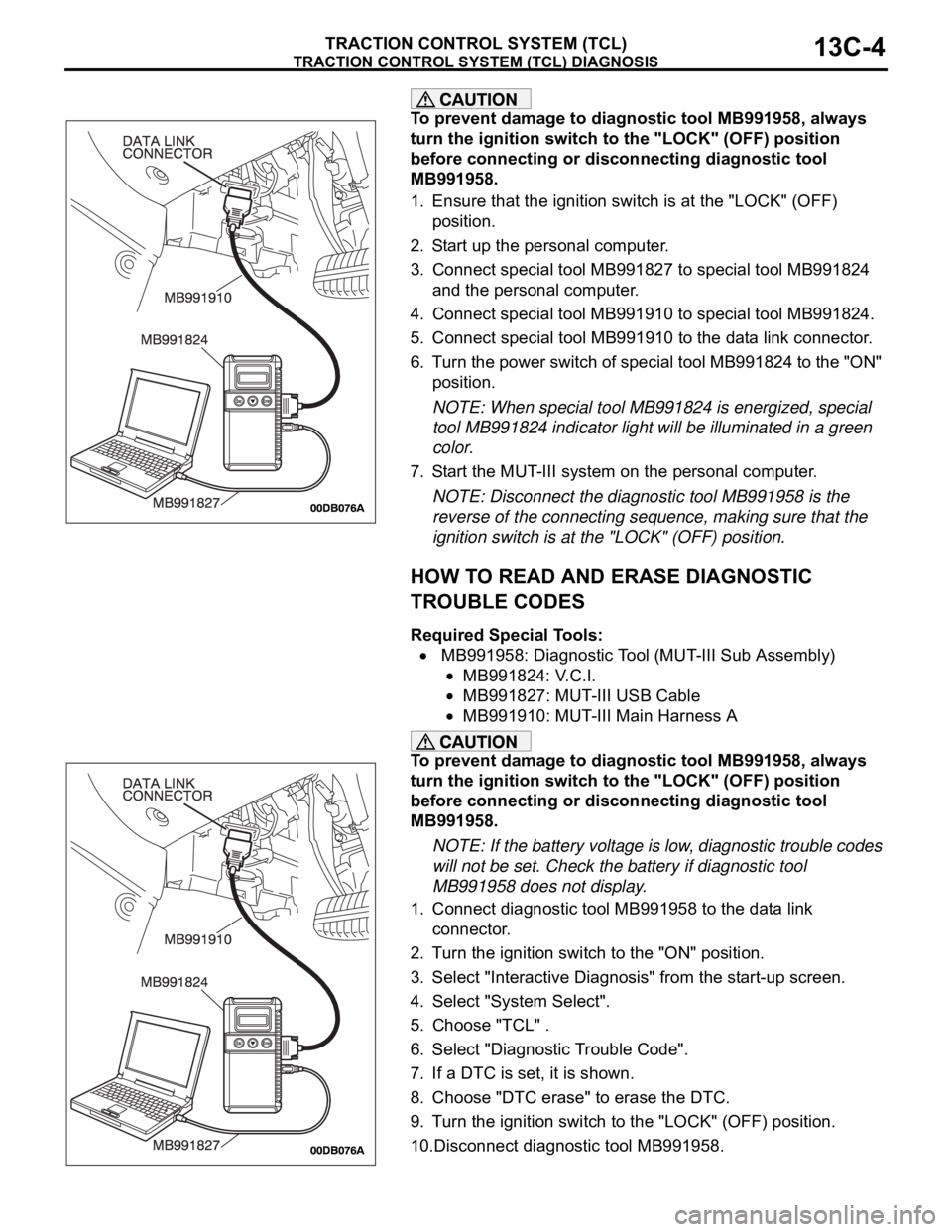
1. Ensure that the ignition switch is at the "LOCK" (OFF)
position.
2. Start up the personal computer.
3. Connect special tool MB991827 to special tool MB991824
and the personal computer.
4. Connect special tool MB991910 to special tool MB991824.
5. Connect special tool MB991910 to the data link connector.
6. Turn the power switch of special tool MB991824 to the "ON"
position.
NOTE: When special tool MB991824 is energized, special
tool MB991824 indicator light will be illuminated in a green
color.
7. Start the MUT-III system on the personal computer.
NOTE: Disconnect the diagnostic tool MB991958 is the
reverse of the connecting sequence, making sure that the
ignition switch is at the "LOCK" (OFF) position.
HOW TO READ AND ERASE DIAGNOSTIC
TROUBLE CODES
Required Special Tools:
MB991958: Diagnostic Tool (MUT-III Sub Assembly)
MB991824: V.C.I.
MB991827: MUT-III USB Cable
MB991910: MUT-III Main Harness A
To prevent damage to diagnostic tool MB991958, always
turn the ignition switch to the "LOCK" (OFF) position
before connecting or disconnecting diagnostic tool
MB991958.
NOTE: If the battery voltage is low, diagnostic trouble codes
will not be set. Check the battery if diagnostic tool
MB991958 does not display.
1. Connect diagnostic tool MB991958 to the data link
connector.
2. Turn the ignition switch to the "ON" position.
3. Select "Interactive Diagnosis" from the start-up screen.
4. Select "System Select".
5. Choose "TCL" .
6. Select "Diagnostic Trouble Code".
7. If a DTC is set, it is shown.
8. Choose "DTC erase" to erase the DTC.
9. Turn the ignition switch to the "LOCK" (OFF) position.
10.Disconnect diagnostic tool MB991958.
Page 1286 of 1500
TRACTION CONTROL SYSTEM (TCL) DIAGNOSIS
TRACTION CONTROL SYSTEM (TCL)13C-7
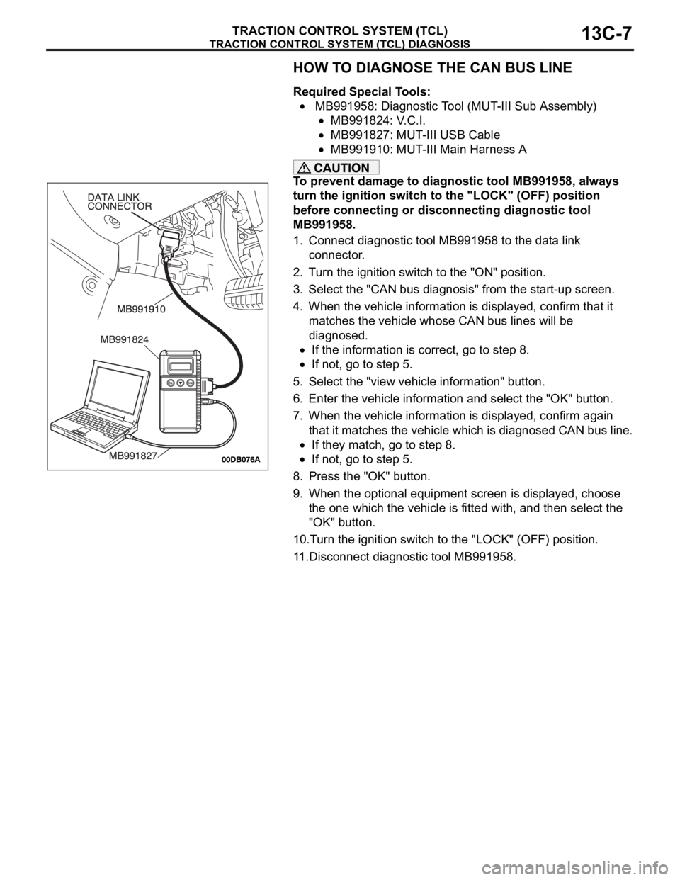
HOW TO DIAGNOSE THE CAN BUS LINE
Required Special Tools:
MB991958: Diagnostic Tool (MUT-III Sub Assembly)
MB991824: V.C.I.
MB991827: MUT-III USB Cable
MB991910: MUT-III Main Harness A
To prevent damage to diagnostic tool MB991958, always
turn the ignition switch to the "LOCK" (OFF) position
before connecting or disconnecting diagnostic tool
MB991958.
1. Connect diagnostic tool MB991958 to the data link
connector.
2. Turn the ignition switch to the "ON" position.
3. Select the "CAN bus diagnosis" from the start-up screen.
4. When the vehicle information is displayed, confirm that it
matches the vehicle whose CAN bus lines will be
diagnosed.
If the information is correct, go to step 8.
If not, go to step 5.
5. Select the "view vehicle information" button.
6. Enter the vehicle information and select the "OK" button.
7. When the vehicle information is displayed, confirm again
that it matches the vehicle which is diagnosed CAN bus line.
If they match, go to step 8.
If not, go to step 5.
8. Press the "OK" button.
9. When the optional equipment screen is displayed, choose
the one which the vehicle is fitted with, and then select the
"OK" button.
10.Turn the ignition switch to the "LOCK" (OFF) position.
11.Disconnect diagnostic tool MB991958.
Page 1291 of 1500
TRACTION CONTROL SYSTEM (TCL) DIAGNOSIS
TRACTION CONTROL SYSTEM (TCL)13C-12
STEP 3. Using diagnostic tool MB991958, read the
diagnostic trouble code.
To prevent damage to diagnostic tool MB991958, always
turn the ignition switch to the "LOCK" (OFF) position
before connecting or disconnecting diagnostic tool
MB991958.
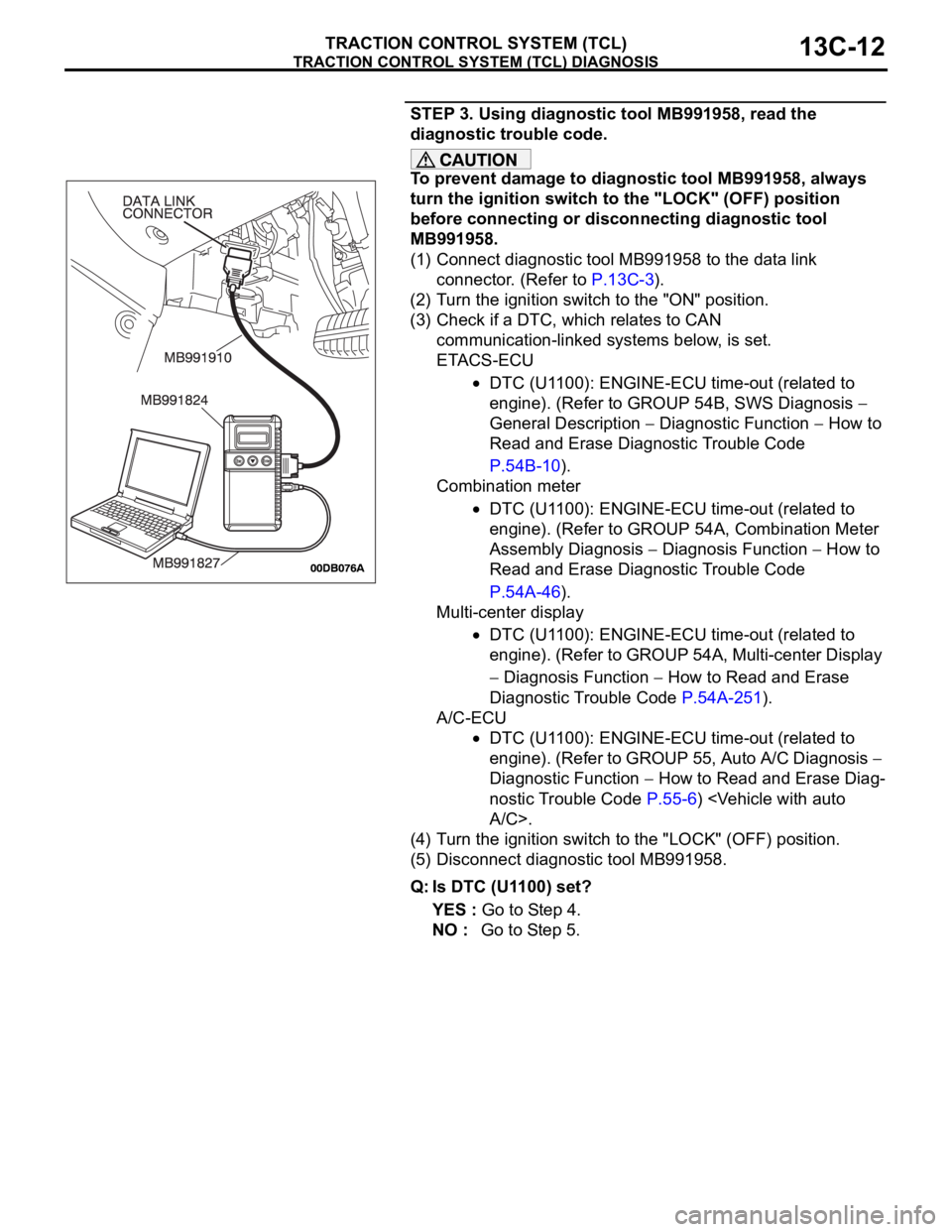
(1) Connect diagnostic tool MB991958 to the data link
connector. (Refer to P.13C-3).
(2) Turn the ignition switch to the "ON" position.
(3) Check if a DTC, which relates to CAN
communication-linked systems below, is set.
ETACS-ECU
DTC (U1100): ENGINE-ECU time-out (related to
engine). (Refer to GROUP 54B, SWS Diagnosis
General Description
Diagnostic Function How to
Read and Erase Diagnostic Trouble Code
P.54B-10).
Combination meter
DTC (U1100): ENGINE-ECU time-out (related to
engine). (Refer to GROUP 54A, Combination Meter
Assembly Diagnosis
Diagnosis Function How to
Read and Erase Diagnostic Trouble Code
P.54A-46).
Multi-center display
DTC (U1100): ENGINE-ECU time-out (related to
engine). (Refer to GROUP 54A, Multi-center Display
Diagnosis Function How to Read and Erase
Diagnostic Trouble Code P.54A-251).
A/C-ECU
DTC (U1100): ENGINE-ECU time-out (related to
engine). (Refer to GROUP 55, Auto A/C Diagnosis
Diagnostic Function
How to Read and Erase Diag-
nostic Trouble Code P.55-6)
(4) Turn the ignition switch to the "LOCK" (OFF) position.
(5) Disconnect diagnostic tool MB991958.
Q: Is DTC (U1100) set?
YES : Go to Step 4.
NO : Go to Step 5.
Page 1295 of 1500
TRACTION CONTROL SYSTEM (TCL) DIAGNOSIS
TRACTION CONTROL SYSTEM (TCL)13C-16
STEP 3. Using diagnostic tool MB991958, read the
diagnostic trouble code.
To prevent damage to diagnostic tool MB991958, always
turn the ignition switch to the "LOCK" (OFF) position
before connecting or disconnecting diagnostic tool
MB991958.
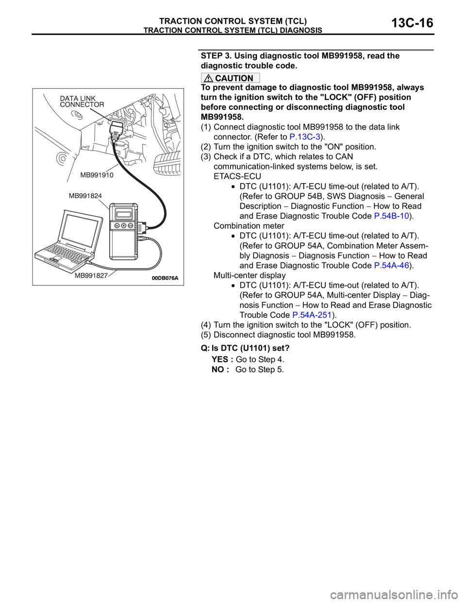
(1) Connect diagnostic tool MB991958 to the data link
connector. (Refer to P.13C-3).
(2) Turn the ignition switch to the "ON" position.
(3) Check if a DTC, which relates to CAN
communication-linked systems below, is set.
ETACS-ECU
DTC (U1101): A/T-ECU time-out (related to A/T).
(Refer to GROUP 54B, SWS Diagnosis
General
Description
Diagnostic Function How to Read
and Erase Diagnostic Trouble Code P.54B-10).
Combination meter
DTC (U1101): A/T-ECU time-out (related to A/T).
(Refer to GROUP 54A, Combination Meter Assem-
bly Diagnosis
Diagnosis Function How to Read
and Erase Diagnostic Trouble Code P.54A-46).
Multi-center display
DTC (U1101): A/T-ECU time-out (related to A/T).
(Refer to GROUP 54A, Multi-center Display
Diag-
nosis Function
How to Read and Erase Diagnostic
Trouble Code P.54A-251).
(4) Turn the ignition switch to the "LOCK" (OFF) position.
(5) Disconnect diagnostic tool MB991958.
Q: Is DTC (U1101) set?
YES : Go to Step 4.
NO : Go to Step 5.
Page 1314 of 1500
TRACTION CONTROL SYSTEM (TCL) DIAGNOSIS
TRACTION CONTROL SYSTEM (TCL)13C-35
STEP 2. Using diagnostic tool MB991958, check TCL
actuator test item09: Engine TCL Drive.
To prevent damage to diagnostic tool MB991958, always
turn the ignition switch to the "LOCK" (OFF) position
before connecting or disconnecting diagnostic tool
MB991958.
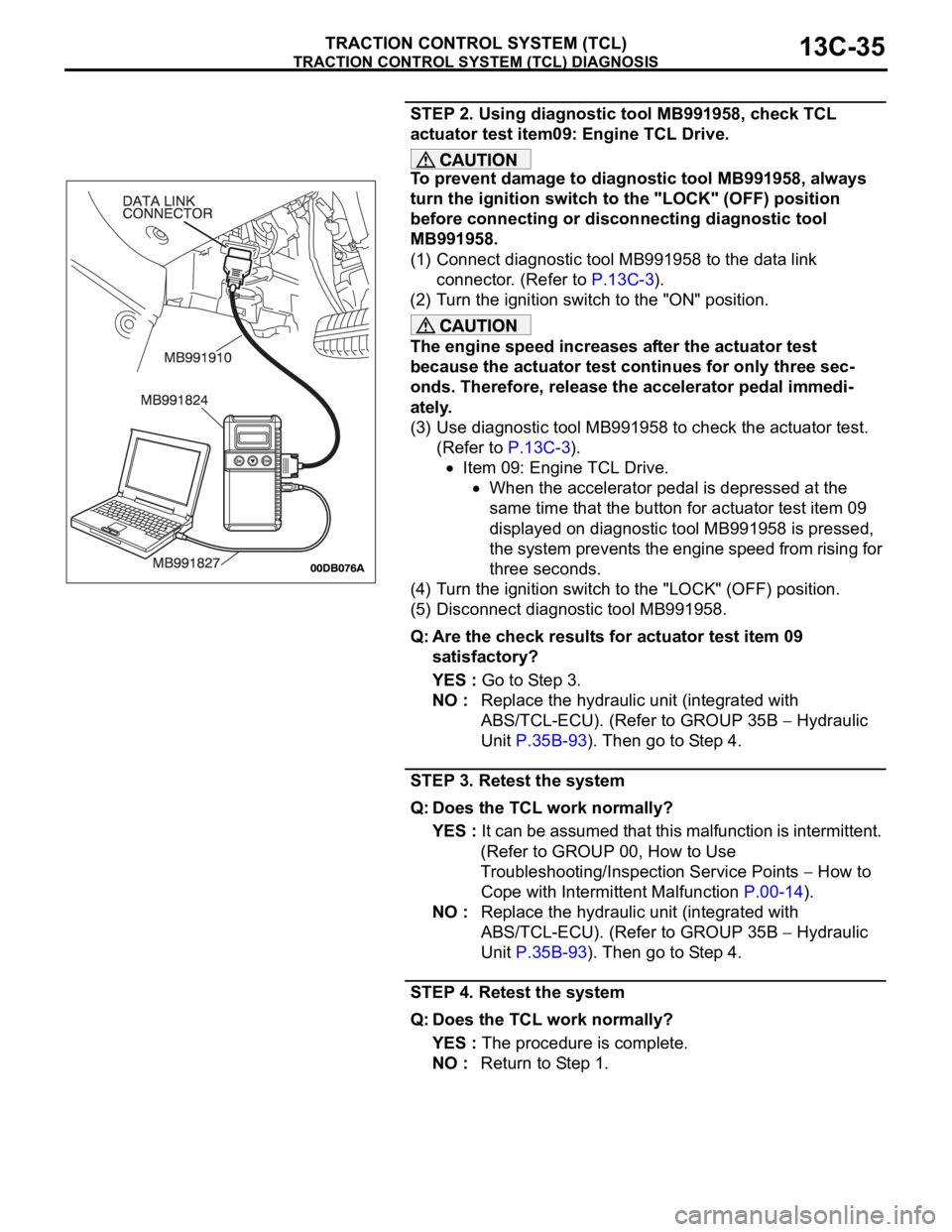
(1) Connect diagnostic tool MB991958 to the data link
connector. (Refer to P.13C-3).
(2) Turn the ignition switch to the "ON" position.
The engine speed increases after the actuator test
because the actuator test continues for only three sec-
onds. Therefore, release the accelerator pedal immedi-
ately.
(3) Use diagnostic tool MB991958 to check the actuator test.
(Refer to P.13C-3).
Item 09: Engine TCL Drive.
When the accelerator pedal is depressed at the
same time that the button for actuator test item 09
displayed on diagnostic tool MB991958 is pressed,
the system prevents the engine speed from rising for
three seconds.
(4) Turn the ignition switch to the "LOCK" (OFF) position.
(5) Disconnect diagnostic tool MB991958.
Q: Are the check results for actuator test item 09
satisfactory?
YES : Go to Step 3.
NO : Replace the hydraulic unit (integrated with
ABS/TCL-ECU). (Refer to GROUP 35B
Hydraulic
Unit P.35B-93). Then go to Step 4.
STEP 3. Retest the system
Q: Does the TCL work normally?
YES : It can be assumed that this malfunction is intermittent.
(Refer to GROUP 00, How to Use
Troubleshooting/Inspection Service Points
How to
Cope with Intermittent Malfunction P.00-14).
NO : Replace the hydraulic unit (integrated with
ABS/TCL-ECU). (Refer to GROUP 35B
Hydraulic
Unit P.35B-93). Then go to Step 4.
STEP 4. Retest the system
Q: Does the TCL work normally?
YES : The procedure is complete.
NO : Return to Step 1.
Page 1315 of 1500

TRACTION CONTROL SYSTEM (TCL) DIAGNOSIS
TRACTION CONTROL SYSTEM (TCL)13C-36
DATA LIST REFERENCE TABLEM1136003500071
NOTE: If the ABS-8 ECU or the active wheel
speed sensor are disconnected, or if the wiring is
an open/ short circuit, the ABS 8 ECU will shut
off power supply to the respective wheel speed
sensor. All other wheel speed sensors will oper-
ate normally. To restore the power supply, the
ignition switch must be turned to the "OFF" posi-
tion then to the "ON" position again.The following items can be read by the diagnostic
tool from the ABS/TCL-ECU input data. (Refer to
P.13C-3).
NOTE: Since the TCL is controlled with the same ABS/TCL-ECU used to control the ABS, the stoplight switch
check item (No.6) used only for the ABS also appear.MUT-III
DIAGNOSTI
C TOOL
DISPLAYITEM
NO.CHECK ITEM CHECKING REQUIREMENTS NORMAL
VA L U E
FL wheel
speed sensor01 Front left wheel speed sensor Drive the vehicle Vehicle speeds
displayed on the
speedometer
and diagnostic
tool are identical. FR wheel
speed sensor02 Front right wheel speed sensor
RL wheel
speed sensor03 Rear left wheel speed sensor
RR wheel
speed sensor04 Rear right left wheel speed
sensor
Power supply
voltage05 ABS/TCL-ECU power supply
voltageIgnition switch power supply
voltageBattery positive
voltage
Stoplamp
switch
(input)*06 Stoplamp switch Depress the brake pedal. ON
Release the brake pedal. OFF
Stoplamp
switch*13 Stoplamp switch Depress the brake pedal. ON
Release the brake pedal. OFF
Pump motor 21 Pump motor When the ABS outputs the
operation permission signal
during drivingON
When the ABS outputs the
operation permission signal
during drivingOFF
Valve relay 30 Valve relayWhen the ABS outputs the
operation permission signal
during drivingON
When the ABS outputs the
operation permission signal
during drivingOFF
TCL mode 35 TCL operation When the TCL outputs the
operation permission signal
during drivingON
When the TCL outputs the
operation inhibition signal
during drivingOFF
Page 1316 of 1500

TRACTION CONTROL SYSTEM (TCL) DIAGNOSIS
TRACTION CONTROL SYSTEM (TCL)13C-37
ACTUATOR TEST REFERENCE TABLEM1136003600067
NOTE: If the ABS-8 ECU or the active wheel
speed sensor are disconnected, or if the wiring is
an open/ short circuit, the ABS 8 ECU will shut
off power supply to the respective wheel speed
sensor. All other wheel speed sensors will oper-
ate normally. To restore the power supply, the
ignition switch must be turned to the "OFF" posi-
tion then to the "ON" position again.The diagnostic tool activates the following actuators
for testing. (Refer to P.13C-3).
NOTE: Since the TCL is controlled with the same ABS/TCL-ECU used to control the ABS, the FL, FR, RL or
RR Wheel ABS Drive testing items (No.01 to 04) used only for the ABS also appear. MUT-III
DIAGNOSTIC TOOL
DISPLAYITEM NO. CHECK ITEM PARTS TO BE ACTIVATED
FL wheel ABS Drive* 01 Solenoid valve for front left wheel Solenoid valves and pump
motors in the hydraulic unit
(simple inspection mode) FR wheel ABS Drive* 02 Solenoid valve for front right wheel
RL wheel ABS Drive* 03 Solenoid valve for rear left wheel
RR wheel ABS
Drive*04 Solenoid valve for rear right wheel
Engine TCL Drive 09 TCL operation check Outputs the engine torque
control signal (engine torque =
0) to PCM for three seconds.