change time MITSUBISHI 380 2005 User Guide
[x] Cancel search | Manufacturer: MITSUBISHI, Model Year: 2005, Model line: 380, Model: MITSUBISHI 380 2005Pages: 1500, PDF Size: 47.87 MB
Page 769 of 1500
AUTO A/C DIAGNOSIS
HEATER, AIR CONDITIONING AND VENTILATION55-68
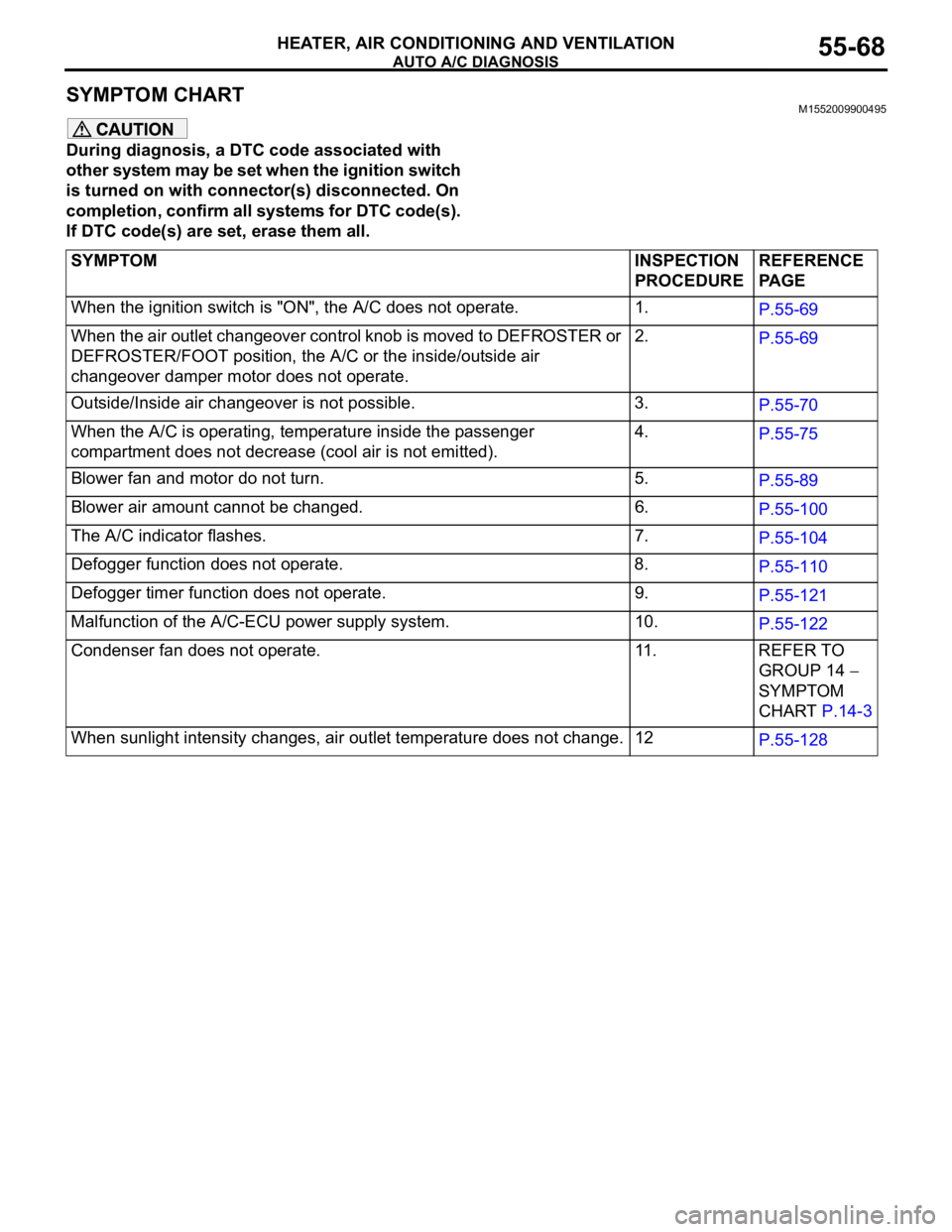
SYMPTOM CHART M1552009900495
During diagnosis, a DTC code associated with
other system may be set when the ignition switch
is turned on with connector(s) disconnected. On
completion, confirm all systems for DTC code(s).
If DTC code(s) are set, erase them all.
SYMPTOM INSPECTION
PROCEDUREREFERENCE
PA G E
When the ignition switch is "ON", the A/C does not operate. 1.
P.55-69
When the air outlet changeover control knob is moved to DEFROSTER or
DEFROSTER/FOOT position, the A/C or the inside/outside air
changeover damper motor does not operate.2.
P.55-69
Outside/Inside air changeover is not possible. 3.
P.55-70
When the A/C is operating, temperature inside the passenger
compartment does not decrease (cool air is not emitted).4.
P.55-75
Blower fan and motor do not turn. 5.
P.55-89
Blower air amount cannot be changed. 6.
P.55-100
The A/C indicator flashes. 7.
P.55-104
Defogger function does not operate. 8.
P.55-110
Defogger timer function does not operate. 9.
P.55-121
Malfunction of the A/C-ECU power supply system. 10.
P.55-122
Condenser fan does not operate. 11. REFER TO
GROUP 14
SYMPTOM
CHART P.14-3
When sunlight intensity changes, air outlet temperature does not change. 12
P.55-128
Page 843 of 1500
ON-VEHICLE SERVICE
HEATER, AIR CONDITIONING AND VENTILATION55-142
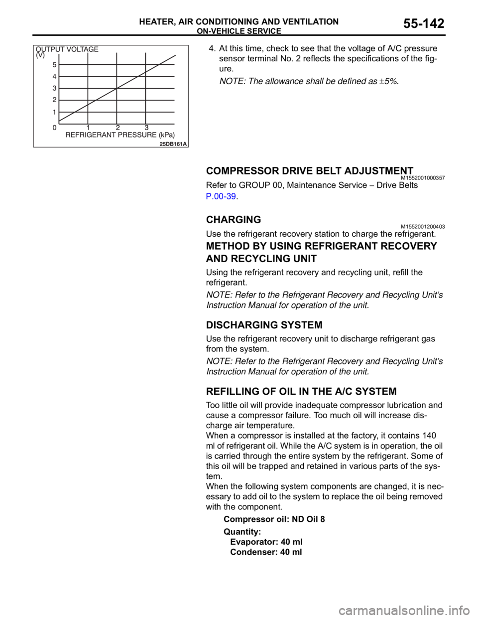
4. At this time, check to see that the voltage of A/C pressure
sensor terminal No. 2 reflects the specifications of the fig-
ure.
NOTE: The allowance shall be defined as
5%.
COMPRESSOR DRIVE BELT ADJUSTMENTM1552001000357
Refer to GROUP 00, Maintenance Service Drive Belts
P.00-39.
CHARGING M1552001200403
Use the refrigerant recovery station to charge the refrigerant.
METHOD BY USING REFRIGERANT RECOVERY
AND RECYCLING UNIT
Using the refrigerant recovery and recycling unit, refill the
refrigerant.
NOTE: Refer to the Refrigerant Recovery and Recycling Unit’s
Instruction Manual for operation of the unit.
DISCHARGING SYSTEM
Use the refrigerant recovery unit to discharge refrigerant gas
from the system.
NOTE: Refer to the Refrigerant Recovery and Recycling Unit’s
Instruction Manual for operation of the unit.
REFILLING OF OIL IN THE A/C SYSTEM
Too little oil will provide inadequate compressor lubrication and
cause a compressor failure. Too much oil will increase dis-
charge air temperature.
When a compressor is installed at the factory, it contains 140
ml of refrigerant oil. While the A/C system is in operation, the oil
is carried through the entire system by the refrigerant. Some of
this oil will be trapped and retained in various parts of the sys-
tem.
When the following system components are changed, it is nec-
essary to add oil to the system to replace the oil being removed
with the component.
Compressor oil: ND Oil 8
Quantity:
Evaporator: 40 ml
Condenser: 40 ml
Page 856 of 1500
HEATER UNIT, HEATER CORE, BLOWER ASSEMBLY AND EVAPORATOR UNIT
HEATER, AIR CONDITIONING AND VENTILATION55-155
INSPECTIONM1552014301157.
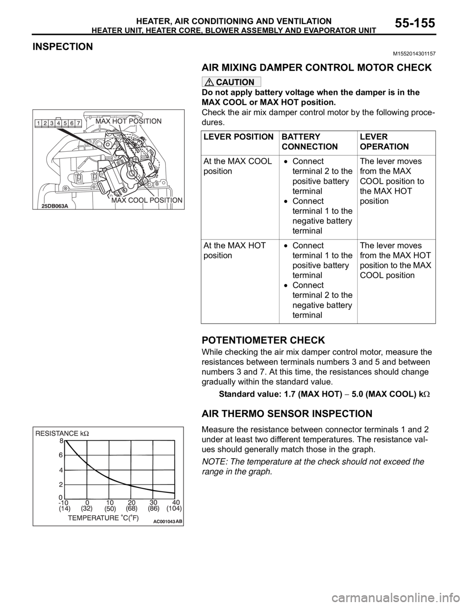
AIR MIXING DAMPER CONTROL MOTOR CHECK
Do not apply battery voltage when the damper is in the
MAX COOL or MAX HOT position.
Check the air mix damper control motor by the following proce-
dures.
.
POTENTIOMETER CHECK
While checking the air mix damper control motor, measure the
resistances between terminals numbers 3 and 5 and between
numbers 3 and 7. At this time, the resistances should change
gradually within the standard value.
Standard value: 1.7 (MAX HOT)
5.0 (MAX COOL) k
AIR THERMO SENSOR INSPECTION
.Measure the resistance between connector terminals 1 and 2
under at least two different temperatures. The resistance val-
ues should generally match those in the graph.
NOTE: The temperature at the check should not exceed the
range in the graph. LEVER POSITION BATTERY
CONNECTIONLEVER
OPERATION
At the MAX COOL
position
Connect
terminal 2 to the
positive battery
terminal
Connect
terminal 1 to the
negative battery
terminalThe lever moves
from the MAX
COOL position to
the MAX HOT
position
At the MAX HOT
position
Connect
terminal 1 to the
positive battery
terminal
Connect
terminal 2 to the
negative battery
terminalThe lever moves
from the MAX HOT
position to the MAX
COOL position
Page 859 of 1500
MOTORS AND TRANSISTOR
HEATER, AIR CONDITIONING AND VENTILATION55-158
INSPECTIONM1551006300338.
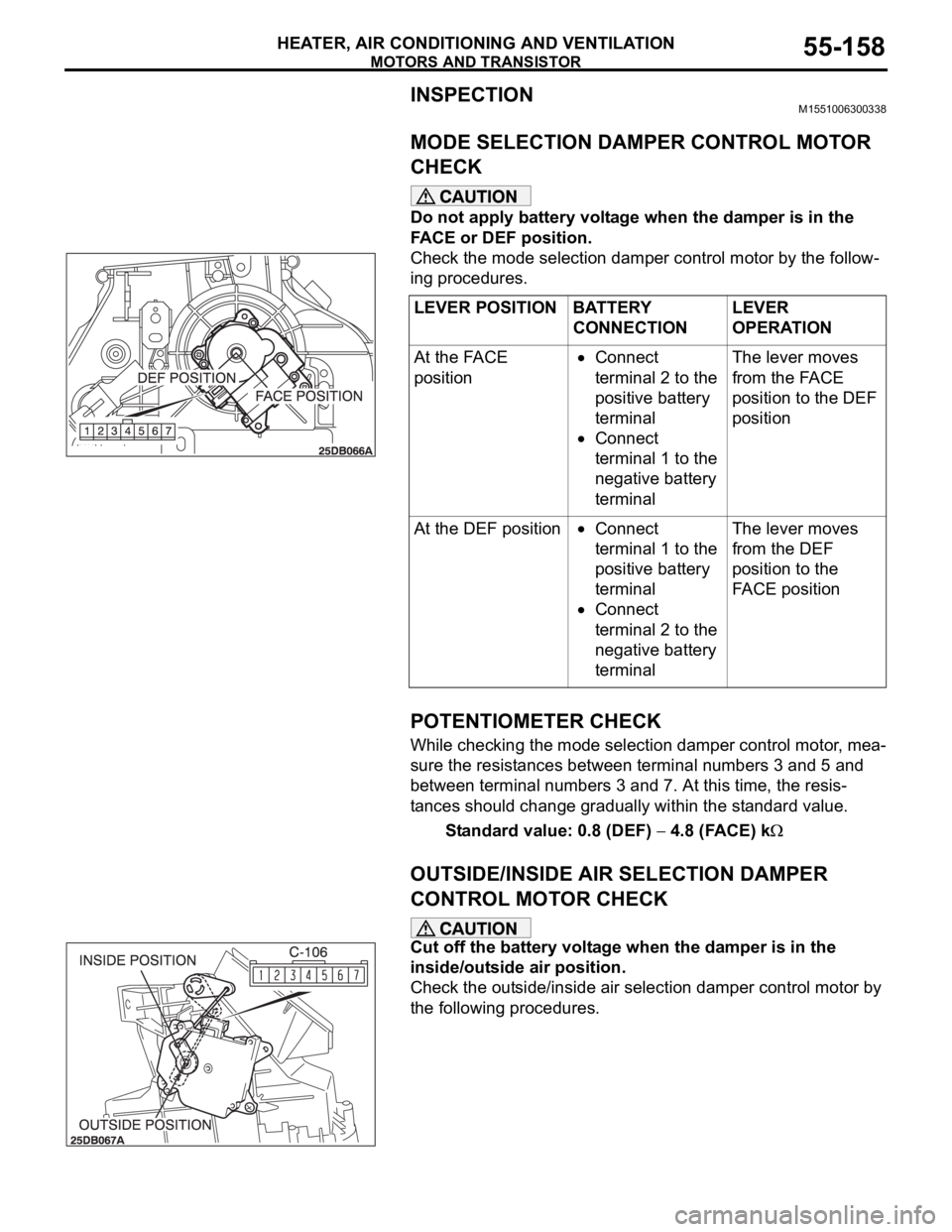
MODE SELECTION DAMPER CONTROL MOTOR
CHECK
Do not apply battery voltage when the damper is in the
FACE or DEF position.
Check the mode selection damper control motor by the follow-
ing procedures.
.
POTENTIOMETER CHECK
While checking the mode selection damper control motor, mea-
sure the resistances between terminal numbers 3 and 5 and
between terminal numbers 3 and 7. At this time, the resis-
tances should change gradually within the standard value.
Standard value: 0.8 (DEF)
4.8 (FACE) k
.
OUTSIDE/INSIDE AIR SELECTION DAMPER
CONTROL MOTOR CHECK
Cut off the battery voltage when the damper is in the
inside/outside air position.
Check the outside/inside air selection damper control motor by
the following procedures.LEVER POSITION BATTERY
CONNECTIONLEVER
OPERATION
At the FACE
position
Connect
terminal 2 to the
positive battery
terminal
Connect
terminal 1 to the
negative battery
terminalThe lever moves
from the FACE
position to the DEF
position
At the DEF position
Connect
terminal 1 to the
positive battery
terminal
Connect
terminal 2 to the
negative battery
terminalThe lever moves
from the DEF
position to the
FACE position
Page 907 of 1500
HOW TO DIAGNOSE
GENERAL
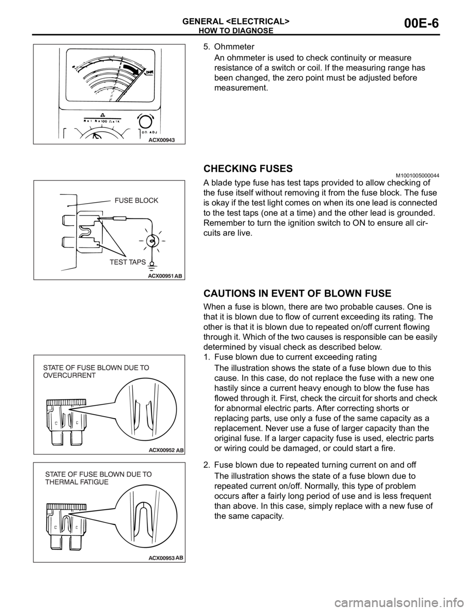
5. Ohmmeter
An ohmmeter is used to check continuity or measure
resistance of a switch or coil. If the measuring range has
been changed, the zero point must be adjusted before
measurement.
CHECKING FUSESM1001005000044
A blade type fuse has test taps provided to allow checking of
the fuse itself without removing it from the fuse block. The fuse
is okay if the test light comes on when its one lead is connected
to the test taps (one at a time) and the other lead is grounded.
Remember to turn the ignition switch to ON to ensure all cir-
cuits are live.
CAUTIONS IN EVENT OF BLOWN FUSE
When a fuse is blown, there are two probable causes. One is
that it is blown due to flow of current exceeding its rating. The
other is that it is blown due to repeated on/off current flowing
through it. Which of the two causes is responsible can be easily
determined by visual check as described below.
1. Fuse blown due to current exceeding rating
The illustration shows the state of a fuse blown due to this
cause. In this case, do not replace the fuse with a new one
hastily since a current heavy enough to blow the fuse has
flowed through it. First, check the circuit for shorts and check
for abnormal electric parts. After correcting shorts or
replacing parts, use only a fuse of the same capacity as a
replacement. Never use a fuse of larger capacity than the
original fuse. If a larger capacity fuse is used, electric parts
or wiring could be damaged, or could start a fire.
2. Fuse blown due to repeated turning current on and off
The illustration shows the state of a fuse blown due to
repeated current on/off. Normally, this type of problem
occurs after a fairly long period of use and is less frequent
than above. In this case, simply replace with a new fuse of
the same capacity.
Page 1047 of 1500

WINDSHIELD WIPER AND WASHER
EXTERIOR51-14
WINDSHIELD WIPER AND WASHER
GENERAL DESCRIPTIONM1511000100558
WINDSHIELD WIPER AND WASHER
OPERATION
.
WINDSHIELD LOW-SPEED (AND
HIGH-SPEED) WIPER OPERATION
If the windshield low-speed wiper switch is turned
to the ON position with the ignition switch at the
"ACC" or "ON" position, the column switch sends
a low-speed wiper ON and high-speed wiper OFF
signals to the front-ECU. This turns the wiper sig-
nal on and the wiper speed control relay off
(low-speed), causing the wipers to operate at
low-speed.
If the windshield high-speed wiper switch is
turned to the ON position, the column switch
sends a low-speed wiper OFF and high-speed
wiper ON signals to the front-ECU. This turns
both the wiper signal and the wiper speed control
relay on (high-speed), causing the wipers to
operate at high-speed.
NOTE: The windshield wiper speed is adjustable
with the built-in wiper speed control relay.
High-speed operations take place when the wiper
speed control relay is set to "ON" and low-speed
operations take place when the wiper speed control
relay is set to "OFF".
.
WINDSHIELD INTERMITTENT WIPER
OPERATION
The ETACS-ECU calculates the wiper operation
interval according to the voltage signal sent from the
column switch. Then the ETACS-ECU sends a signal
to the front-ECU. The front-ECU determines the
wiper operation interval and turns on the wiper relay
signal relay. This causes the wiper auto stop relay to
turn on. Then the wiper auto stop relay will turn off
after the wipers reach the park position. This causes
the wiper signal relay and then the wipers to turn off.
If the wiper signal relay remains off for the wiper
operation interval, the relay turns on again, causing
the wipers to operate in intermittent mode.
.
WINDSHIELD MIST WIPER OPERATION
If the windshield mist wiper switch is turned to the
ON position with the ignition switch at the "ACC"
or "ON" position, the mist wiper high-speed oper-
ation signal is sent to the front-ECU. This signal
turns on the wiper speed control relay, causing
the wipers to work at high-speed while the mist
switch is on.
While the windshield mist wiper switch remains
turned on when the intermittent mode is still work-
ing, the wipers work as the mist wiper. However,
the wipers return to the intermittent mode again
when the switch is changed back to "INT" posi-
tion.
To prevent the windshield mist wiper from operat-
ing when the windshield wiper switch is turned
OFF, the windshield mist wiper does not work for
0.5 second after the windshield intermittent wiper
switch, the windshield low-speed wiper switch
and the windshield high-speed wiper switch are
turned OFF.
.
WINDSHIELD WASHER OPERATION
If the windshield washer switch is turned to the
ON position with the ignition switch at "ACC" or
"ON" position, the windshield washer ON signal is
sent to the front-ECU. After 0.3 second, the wind-
shield wiper signal turns on. After the windshield
washer switch signal turns off, the windshield
wiper signal turns off in three seconds.
If the windshield washer switch is turned on while
the windshield wiper is at intermittent mode, and
the windshield washer switch is turned OFF
within 0.2 second, the wiper works only once to
perform mist operation. When the windshield
washer switch is turned on for more than 0.2 sec-
ond, the wiper performs the same movement as
normal condition from the time when 0.2 second
has elapsed, and then returns to intermittent
operation.
WINDSHIELD WIPER AND WASHER DIAGNOSISM1511000700389
The windshield wiper and washer are controlled by
the Simplified Wiring System (SWS). For trouble-
shooting, refer to GROUP 54B, SWS Diagnosis
P.54B-10.NOTE: Even when the ETACS-ECU has failed, the
windshield wiper can work at low speed as fail-safe
mode. (Normally, the windshield wiper operates
when the ignition switch is at the "ACC" position. But,
if it enters the fail-safe mode, the wiper can operate
only when the ignition switch is at the "ON" position.)
Page 1135 of 1500
KEYLESS ENTRY SYSTEM
BODY42-68
If none of the doors is opened or the ignition key
is not inserted in the ignition switch within 30 sec-
onds after the doors are unlocked using the
transmitter, the ETACS-ECU will relock the doors
automatically. This is called "Timer lock function."
This timer lock function prevents accidental
unlocking of doors. The adjustment function
allows you to change the timer lock period from 30 seconds (default setting) to 60, 120 or 180
seconds. For further details on using the
multi-center display (middle grade type) to adjust
the timer lock period, refer to GROUP 54B,
On-vehicle Service P.54B-486.
NOTE: The timer lock period begins when the doors
are unlocked, and ends when the doors is relocked
automatically.
KEYLESS ENTRY SYSTEM DIAGNOSISBGBCJGAI
The keyless entry system is controlled by the Simpli-
fied Wiring System (SWS). Refer to GROUP 54B,
SWS Diagnosis P.54B-57.
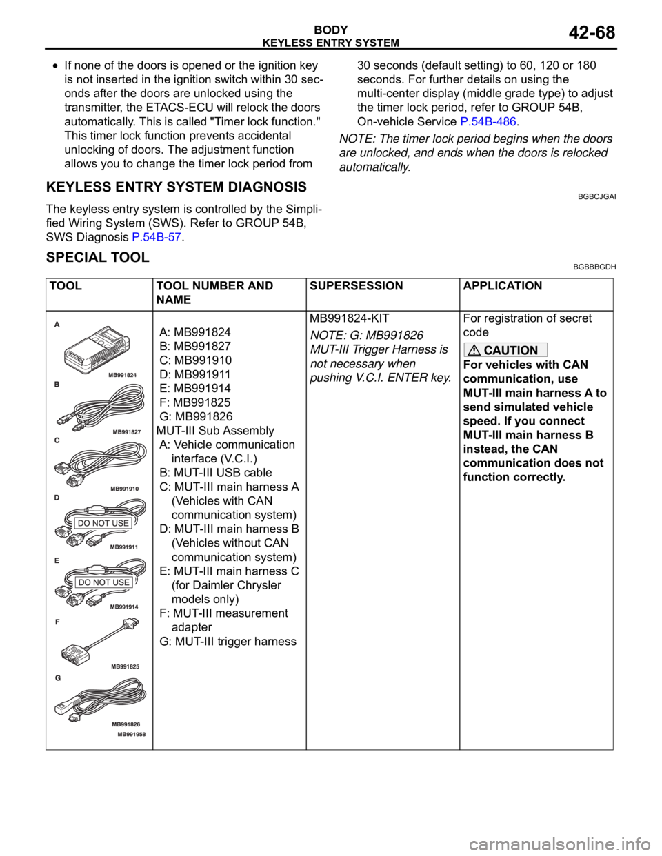
SPECIAL TOOLBGBBBGDH
TOOL TOOL NUMBER AND
NAMESUPERSESSION APPLICATION
A: MB991824
B: MB991827
C: MB991910
D: MB991911
E: MB991914
F: MB991825
G: MB991826
MUT-III Sub Assembly
A: Vehicle communication
interface (V.C.I.)
B: MUT-III USB cable
C: MUT-III main harness A
(Vehicles with CAN
communication system)
D: MUT-III main harness B
(Vehicles without CAN
communication system)
E: MUT-III main harness C
(for Daimler Chrysler
models only)
F: MUT-III measurement
adapter
G: MUT-III trigger harnessMB991824-KIT
NOTE: G: MB991826
MUT-III Trigger Harness is
not necessary when
pushing V.C.I. ENTER key.For registration of secret
code
For vehicles with CAN
communication, use
MUT-III main harness A to
send simulated vehicle
speed. If you connect
MUT-III main harness B
instead, the CAN
communication does not
function correctly.
Page 1138 of 1500

KEYLESS ENTRY SYSTEM
BODY42-71
KEYLESS ENTRY SYSTEM INSPECTIONBGBHCDAE
Check the following items. If defective, refer to GROUP 54B,
SWS Diagnosis P.54B-10).
1. Operate the transmitter to check that the doors can be
locked and unlocked.
NOTE: The adjustment function allows you to change the
unlock operation setting as follows. Prior to that check, con-
firm which setting is activated.
.
a. When the unlock button is pressed once, the driver's
door will be unlocked. Then when the button is pressed
once again, all the doors will be opened (initial setting).
b. When the unlock button is pressed only once, all the
doors will be opened.
2. Press the trunk lid button of transmitter twice (press once,
and then press again within 5 seconds) and confirm that the
trunk lid opens.
3. Operate the transmitter to check that the answerback
function works in response to doors locking/unlocking.
NOTE: The adjustment function allows you to change the
hazard answerback setting as follows. Prior to that check,
confirm which setting is activated.
.
a. Turn-signal lights: Flash once when doors are locked,
and twice when unlocked (initial setting)
b. Turn-signal lights: Flash once when doors are locked,
but does not flash when unlocked.
c. Turn-signal lights: Do not flash when doors are locked,
but flash twice when unlocked.
d. Turn-signal lights: Do not flash when doors are locked
and unlocked.
NOTE: The adjustment function allows you to change the
horn answerback setting as follows. Prior to that check, con-
firm which setting is activated.
.
a. Horn: Sounds once when the lock button is pressed.
b. Horn: Sounds once when the lock button is pressed (ini-
tial setting).
c. Horn: Does not sound.
KEYLESS ENTRY SYSTEM TIMER LOCK
FUNCTION INSPECTION
BGBEBDIA
If the doors are not locked within 30 seconds after the unlock
button is pressed, refer to GROUP 54B, SWS Diagnosis
P.54B-10.
NOTE: If either of the doors is opened or the key is inserted in
the ignition switch within that 30-second period, the timer lock
function will be cancelled.
Page 1139 of 1500

KEYLESS ENTRY SYSTEM
BODY42-72
NOTE: The adjustment function allows you to change the timer
lock period from 30 seconds (initial setting) to 60, 120 or 180
seconds. Prior to this inspection, confirm which setting is acti-
vated.
ENABLING/DISABLING THE ANSWERBACK
FUNCTION
BGBDGCGD
When the doors are locked or unlocked by using the transmit-
ter, the dome light will flash/illuminate, the turn-signal lights will
flash (hazard answerback), or the horn will sound (horn
answerback) to inform the driver.
The hazard answerback and horn answerback functions can be
enabled or disabled according to the following procedure:
ENABLING/DISABLING THE HAZARD
ANSWERBACK FUNCTION
.
How to adjust hazard answerback when the trans-
mitter is used to lock doors
1. Remove the ignition key.
2. Push the ”unlock” button and then push the ”lock“ button
within 4 seconds to 10 seconds.
3. Release the ”lock” button within 10 seconds after Step 2 and
then release the “unlock” button. The ETACS-ECU tone
alarm will sound, indicating that the hazard answerback
function can be enabled or disabled when the doors are
locked.
Enable the hazard answerback function when the
doors are locked: The ETACS-ECU tone alarm will
sound once.
Disable the hazard answerback function when the
doors are locked: The ETACS-ECU tone alarm will
sound twice.
.
How to adjust hazard answerback when the
transmitter is used to unlock doors
1. Remove the ignition key.
2. Push the ”unlock” button and then push the ”lock“ button
within 4 seconds to 10 seconds.
3. Release the ”lock” button within 10 seconds after Step 2 and
then release the “unlock” button. The ETACS-ECU tone
alarm will sound, indicating that the hazard answerback
function can be enabled or disabled when the door are
unlocked.
Enable the hazard answerback function when the
doors are unlocked: The ETACS-ECU tone alarm
will sound once.
Disable the hazard answerback function when the
doors are unlocked: The ETACS-ECU tone alarm
will sound twice.
Page 1179 of 1500
ON-VEHICLE SERVICE
BASIC BRAKE SYSTEM35A-14
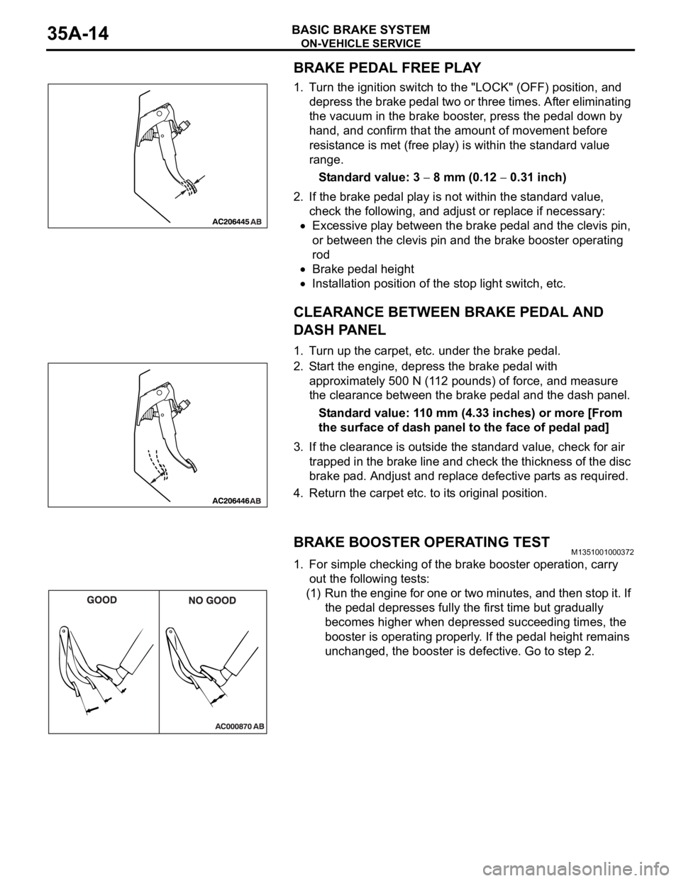
BRAKE PEDAL FREE PLAY
1. Turn the ignition switch to the "LOCK" (OFF) position, and
depress the brake pedal two or three times. After eliminating
the vacuum in the brake booster, press the pedal down by
hand, and confirm that the amount of movement before
resistance is met (free play) is within the standard value
range.
Standard value: 3
8 mm (0.12 0.31 inch)
2. If the brake pedal play is not within the standard value,
check the following, and adjust or replace if necessary:
Excessive play between the brake pedal and the clevis pin,
or between the clevis pin and the brake booster operating
rod
Brake pedal height
Installation position of the stop light switch, etc.
CLEARANCE BETWEEN BRAKE PEDAL AND
DASH PANEL
1. Turn up the carpet, etc. under the brake pedal.
2. Start the engine, depress the brake pedal with
approximately 500 N (112 pounds) of force, and measure
the clearance between the brake pedal and the dash panel.
Standard value: 110 mm (4.33 inches) or more [From
the surface of dash panel to the face of pedal pad]
3. If the clearance is outside the standard value, check for air
trapped in the brake line and check the thickness of the disc
brake pad. Andjust and replace defective parts as required.
4. Return the carpet etc. to its original position.
BRAKE BOOSTER OPERATING TESTM1351001000372
1. For simple checking of the brake booster operation, carry
out the following tests:
(1) Run the engine for one or two minutes, and then stop it. If
the pedal depresses fully the first time but gradually
becomes higher when depressed succeeding times, the
booster is operating properly. If the pedal height remains
unchanged, the booster is defective. Go to step 2.