clock MITSUBISHI 380 2005 User Guide
[x] Cancel search | Manufacturer: MITSUBISHI, Model Year: 2005, Model line: 380, Model: MITSUBISHI 380 2005Pages: 1500, PDF Size: 47.87 MB
Page 660 of 1500
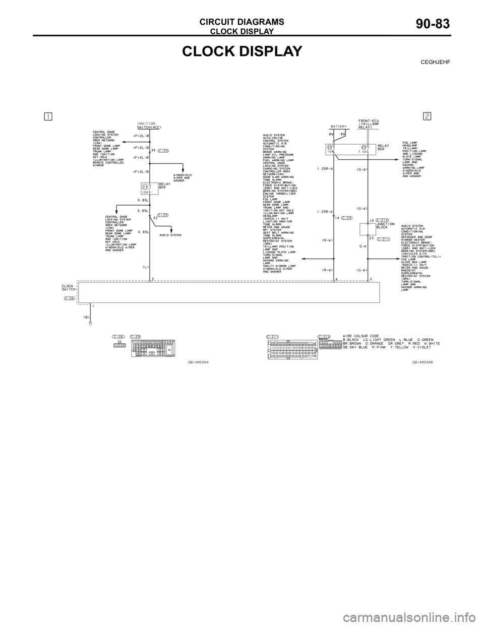
CLOCK DISPLAY
CIRCUIT DIAGRAMS90-83
CLOCK DISPLAYCEGHJEHF
Page 852 of 1500
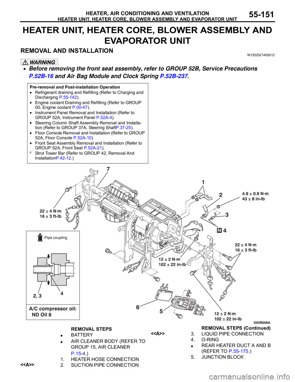
HEATER UNIT, HEATER CORE, BLOWER ASSEMBLY AND EVAPORATOR UNIT
HEATER, AIR CONDITIONING AND VENTILATION55-151
HEATER UNIT, HEATER CORE, BLOWER ASSEMBLY AND
EVAPORATOR UNIT
REMOVAL AND INSTALLATIONM1552021400012
Before removing the front seat assembly, refer to GROUP 52B, Service Precautions
P.52B-16 and Air Bag Module and Clock Spring P.52B-237.
Pre-removal and Post-installation Operation
Refrigerant draining and Refilling (Refer to Charging and
Discharging P.55-142).
Engine coolant Draining and Refilling (Refer to GROUP
00, Engine coolant P.00-47).
Instrument Panel Removal and Installation (Refer to
GROUP 52A, Instrument Panel P.52A-4).
Steering Column Shaft Assembly Removal and Installa-
tion (Refer to GROUP 37A, Steering ShaftP.37-25).
Floor Console Removal and Installation (Refer to GROUP
52A, Floor Console P.52A-10).
Front Seat Assembly Removal and Installation (Refer to
GROUP 52A, Front Seat P.52A-21).
² Strut Tower Bar (Refer to GROUP 42, Removal And
InstallationP.42-12.)
REMOVAL STEPS
BATTERY
AIR CLEANER BODY (REFER TO
GROUP 15, AIR CLEANER
P.15-4.)
1. HEATER HOSE CONNECTION
<>2. SUCTION PIPE CONNECTION
<>3. LIQUID PIPE CONNECTION
4. O-RING
REAR HEATER DUCT A AND B
(REFER TO P.55-175.)
5. JUNCTION BLOCKREMOVAL STEPS (Continued)
Page 872 of 1500
Page 875 of 1500
REFRIGERANT LINE
HEATER, AIR CONDITIONING AND VENTILATION55-174
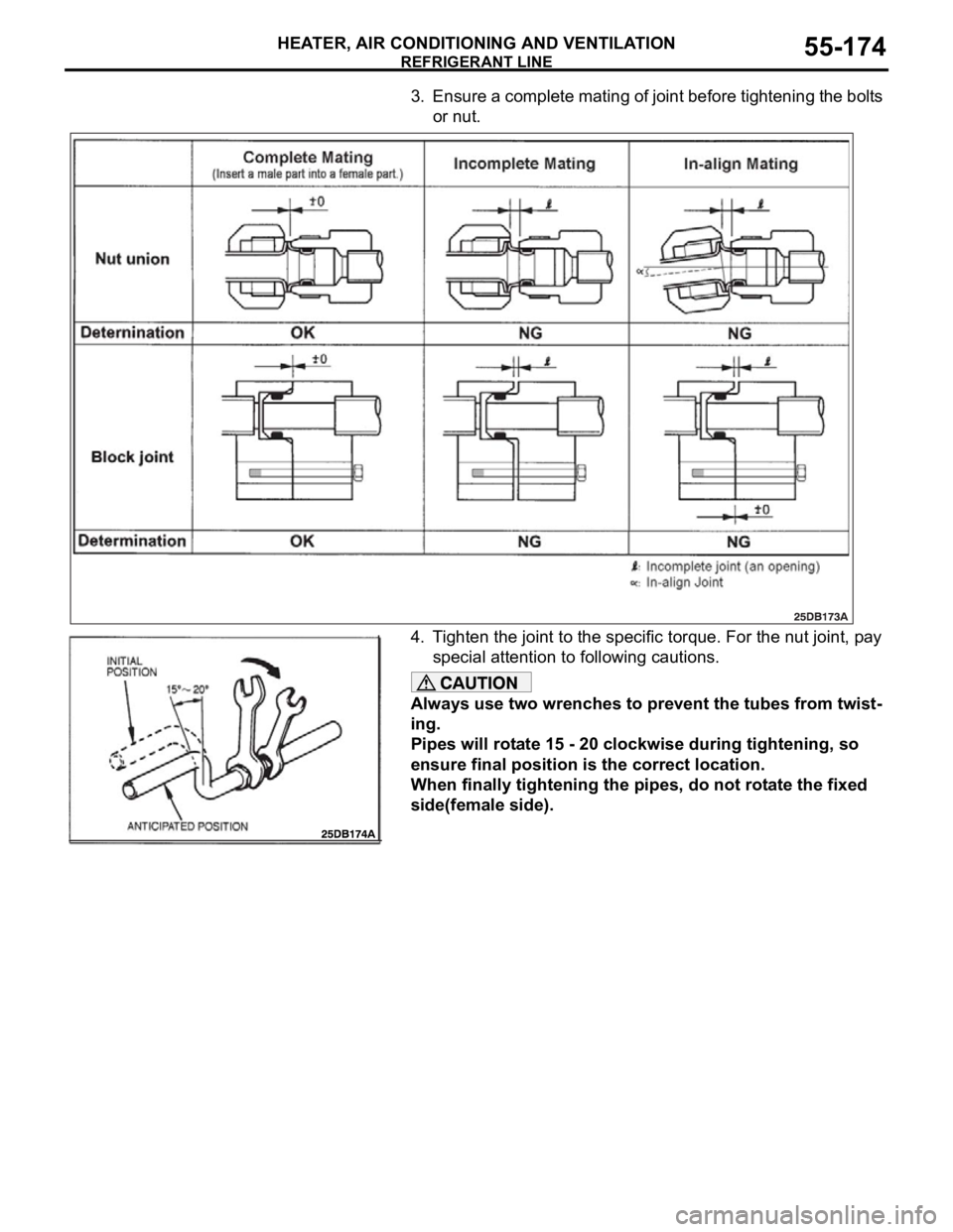
3. Ensure a complete mating of joint before tightening the bolts
or nut.
4. Tighten the joint to the specific torque. For the nut joint, pay
special attention to following cautions.
Always use two wrenches to prevent the tubes from twist-
ing.
Pipes will rotate 15 - 20 clockwise during tightening, so
ensure final position is the correct location.
When finally tightening the pipes, do not rotate the fixed
side(female side).
Page 942 of 1500
ON-VEHICLE SERVICE
ENGINE COOLING14-27
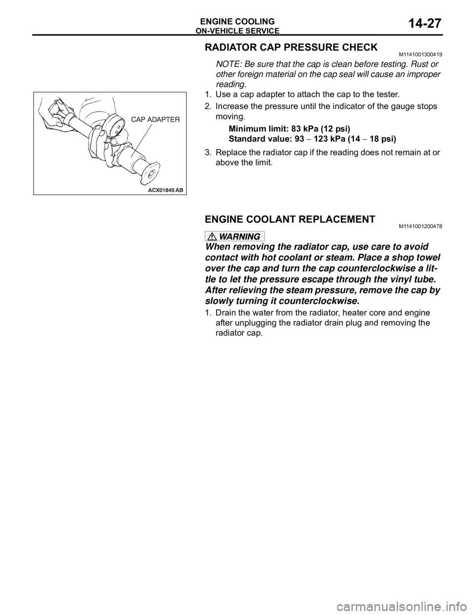
RADIATOR CAP PRESSURE CHECKM1141001300419
NOTE: Be sure that the cap is clean before testing. Rust or
other foreign material on the cap seal will cause an improper
reading.
1. Use a cap adapter to attach the cap to the tester.
2. Increase the pressure until the indicator of the gauge stops
moving.
Minimum limit: 83 kPa (12 psi)
Standard value: 93
123 kPa (14 18 psi)
3. Replace the radiator cap if the reading does not remain at or
above the limit.
ENGINE COOLANT REPLACEMENTM1141001200478
When removing the radiator cap, use care to avoid
contact with hot coolant or steam. Place a shop towel
over the cap and turn the cap counterclockwise a lit-
tle to let the pressure escape through the vinyl tube.
After relieving the steam pressure, remove the cap by
slowly turning it counterclockwise.
1. Drain the water from the radiator, heater core and engine
after unplugging the radiator drain plug and removing the
radiator cap.
Page 1026 of 1500
CROSSMEMBER
POWER PLANT MOUNT32-9
CROSSMEMBER
REMOVAL AND INSTALLATIONM1321003200551
Before removing the steering wheel and air bag module assembly, always refer to GROUP 52B -
Service Precautions (P.52B-16), Air bag Module and Clock Spring (P.52B-237). Also, set the front
wheels so that they are facing straight forward, and remove the ignition key. If you fail to do this,
the SRS clock spring will be damaged, causing the SRS air bag to be inoperative and serious
injury.
*1: Indicates parts which should be initially tightened, and then fully tightened after placing the
vehicle horizontally and loading the full weight of the engine on the vehicle body.
*2: Indicates parts which should be temporarily tightened, and then fully tightened with the vehicle
on the ground in the unladen condition.
Pre-removal Operation
Power Steering Fluid Draining (Refer to GROUP 37,
On-vehicle Service Fluid Replacement P.37-18).
Power Steering Hoses Removal and Installation (Refer to
GROUP 37, Power Steering Hoses P.37A-57).
Air Bag Module and Steering Wheel Assembly Removal
(Refer to GROUP 37, Steering Wheel P.37-23).
Clock Spring Removal (Refer to GROUP 52B, Air Bag
Module and Clock Spring P.52B-237).
Floor Console Assembly Removal (Refer to GROUP 52A,
Floor Console Assembly P.52A-10).
Front Scuff Plate (LH) and Cowl Side Trim (LH) Removal
(Refer to GROUP 52A, Trims P.52A-11).
Trunk Lid Release Handle Cover Removal (Refer to
GROUP 42, Trunk Lid P.42-63).
Accelerator Stopper Removal (Refer to GROUP 17,
Accelerator Pedal P.17-9).
Front Floor Carpet Removal
Centremember Removal (Refer to P.32-7).Post-installation Operation
Centremember Installation (Refer to P.32-7).
Front Floor Carpet Installation
Accelerator Stopper Installation (Refer to GROUP 17,
Accelerator Pedal P.17-9).
Trunk Lid Release Handle Cover Installation (Refer to
GROUP 42, Trunk Lid P.42-63).
Front Scuff Plate (LH) and Cowl Side Trim (LH) Installa-
tion (Refer to GROUP 52A, Trims P.52A-11).
Floor Console Assembly Installation (Refer to GROUP
52A, Floor Console Assembly P.52A-10).
Clock Spring Installation (Refer to GROUP 52B, Air Bag
Module and Clock Spring P.52B-237).
Steering Wheel Assembly and Air Bag Module Installation
(Refer to P.37-23).
Check the dust cover for cracks or damage by pushing it
with your finger.
Power Steering Fluid Supplying (Refer to GROUP 37,
On-vehicle Service Fluid Replacement P.37-18).
Power Steering Fluid Line Bleeding (Refer to P.37-18).
Checking Steering Wheel Position with Wheels Straight
Ahead.
Front Wheel Alignment Adjustment (Refer to GROUP 33,
On-vehicle Service
Front Wheel Alignment Check and
Adjustment P.33-6).
Page 1129 of 1500
TRUNK LID
BODY42-62
TRUNK LID HEIGHT ADJUSTMENTM1421008300044
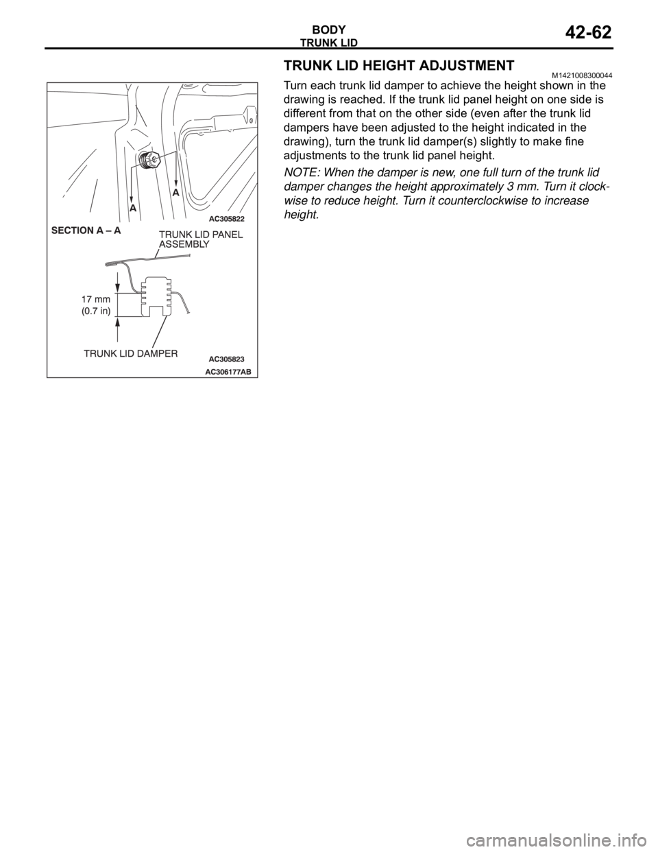
Turn each trunk lid damper to achieve the height shown in the
drawing is reached. If the trunk lid panel height on one side is
different from that on the other side (even after the trunk lid
dampers have been adjusted to the height indicated in the
drawing), turn the trunk lid damper(s) slightly to make fine
adjustments to the trunk lid panel height.
NOTE: When the damper is new, one full turn of the trunk lid
damper changes the height approximately 3 mm. Turn it clock-
wise to reduce height. Turn it counterclockwise to increase
height.
Page 1178 of 1500
ON-VEHICLE SERVICE
BASIC BRAKE SYSTEM35A-13
ON-VEHICLE SERVICE
BRAKE PEDAL CHECK AND ADJUSTMENTM1351000900446
BRAKE PEDAL HEIGHT
1. Turn up the carpet, etc. under the brake pedal.
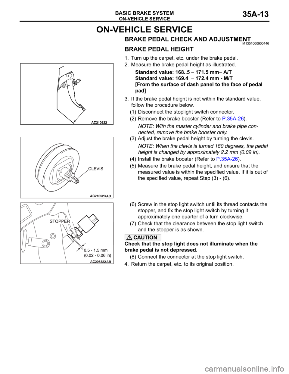
2. Measure the brake pedal height as illustrated.
Standard value: 168..5
171.5 mm A/T
Standard value: 169.4
172.4 mm - M/T
[From the surface of dash panel to the face of pedal
pad]
3. If the brake pedal height is not within the standard value,
follow the procedure below.
(1) Disconnect the stoplight switch connector.
(2) Remove the brake booster (Refer to P.35A-26).
NOTE: With the master cylinder and brake pipe con-
nected, remove the brake booster only.
(3) Adjust the brake pedal height by turning the clevis.
NOTE: When the clevis is turned 180 degrees, the pedal
height is changed by approximately 2.2 mm (0.09 in).
(4) Install the brake booster (Refer to P.35A-26).
(5) Measure the brake pedal height, and ensure that the
measured value is within the specified value. If it is out of
the specified value, repeat Step (3) - (6).
(6) Screw in the stop light switch until its thread contacts the
stopper, and fix the stop light switch by turning it
approximately one quarter of a turn clockwise.
(7) Check that the clearance between the stop light switch
and the stopper is as shown.
Check that the stop light does not illuminate when the
brake pedal is not depressed.
(8) Connect the connector at the stop light switch.
4. Return the carpet, etc. to its original position.
Page 1243 of 1500
PRECAUTIONS BEFORE SERVICE
GENERAL00-22
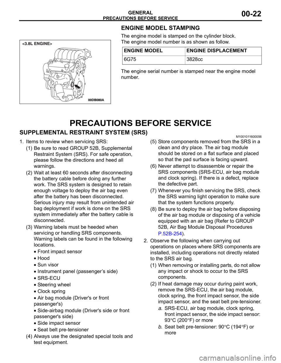
ENGINE MODEL STAMPING
The engine model is stamped on the cylinder block.
The engine model number is as shown as follow.
The engine serial number is stamped near the engine model
number.
PRECAUTIONS BEFORE SERVICE
SUPPLEMENTAL RESTRAINT SYSTEM (SRS)M1001011600056
1. Items to review when servicing SRS:
(1) Be sure to read GROUP 52B, Supplemental
Restraint System (SRS). For safe operation,
please follow the directions and heed all
warnings.
(2) Wait at least 60 seconds after disconnecting
the battery cable before doing any further
work. The SRS system is designed to retain
enough voltage to deploy the air bag even
after the battery has been disconnected.
Serious injury may result from unintended air
bag deployment if work is done on the SRS
system immediately after the battery cable is
disconnected.
(3) Warning labels must be heeded when
servicing or handling SRS components.
Warning labels can be found in the following
locations.
Front impact sensor
Hood
Sun visor
Instrument panel (passenger ’s side)
SRS-ECU
Steering wheel
Clock spring
Air bag module (Driver's or front
passenger's)
Side-airbag module (Driver's side or front
passenger's side)
Side impact sensor
Seat belt pre-tensioner
(4) Always use the designated special tools and
test equipment.(5) Store components removed from the SRS in a
clean and dry place. The air bag module
should be stored on a flat surface and placed
so that the pad surface is facing upward.
(6) Never attempt to disassemble or repair the
SRS components (SRS-ECU, air bag module
and clock spring). If there is a defect, replace
the defective part.
(7) Whenever you finish servicing the SRS, check
the SRS warning light operation to make sure
that the system functions properly.
(8) Be sure to deploy the air bag before disposing
of the air bag module or disposing of a vehicle
equipped with an air bag (Refer to GROUP
52B, Air Bag Module Disposal Procedures
P.52B-254).
2. Observe the following when carrying out
operations on places where SRS components are
installed, including operations not directly related
to the SRS air bag.
(1) When removing or installing parts, do not allow
any impact or shock to occur to the SRS
components.
(2) If heat damage may occur during paint work,
remove the SRS-ECU, the air bag module,
clock spring, the front impact sensor, the side
impact sensor, and the seat belt pre-tensioner.
a.SRS-ECU, air bag module, clock spring,
front impact sensor, the side impact sensor:
93
C (200F) or more
b.Seat belt pre-tensioner: 90
C (194F) or
more ENGINE MODEL ENGINE DISPLACEMENT
6G75 3828cc
Page 1264 of 1500
MAINTENANCE SERVICE
GENERAL00-43
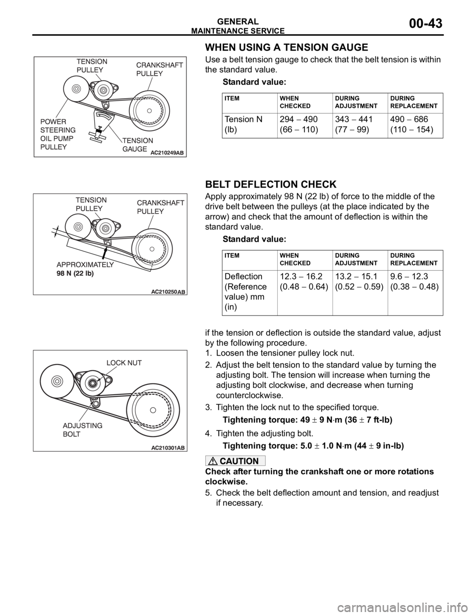
WHEN USING A TENSION GAUGE
Use a belt tension gauge to check that the belt tension is within
the standard value.
Standard value:
.
BELT DEFLECTION CHECK
Apply approximately 98 N (22 lb) of force to the middle of the
drive belt between the pulleys (at the place indicated by the
arrow) and check that the amount of deflection is within the
standard value.
Standard value:
.if the tension or deflection is outside the standard value, adjust
by the following procedure.
1. Loosen the tensioner pulley lock nut.
2. Adjust the belt tension to the standard value by turning the
adjusting bolt. The tension will increase when turning the
adjusting bolt clockwise, and decrease when turning
counterclockwise.
3. Tighten the lock nut to the specified torque.
Tightening torque: 49
9 Nm (36 7 ft-lb)
4. Tighten the adjusting bolt.
Tightening torque: 5.0
1.0 Nm (44 9 in-lb)
Check after turning the crankshaft one or more rotations
clockwise.
5. Check the belt deflection amount and tension, and readjust
if necessary.
ITEM WHEN
CHECKEDDURING
ADJUSTMENTDURING
REPLACEMENT
Te n s i o n N
(lb)294 490
(66
110)343
441
(77
99)490
686
(110
154)
ITEM WHEN
CHECKEDDURING
ADJUSTMENTDURING
REPLACEMENT
Deflection
(Reference
value) mm
(in)12.3 16.2
(0.48
0.64)13.2
15.1
(0.52
0.59)9.6
12.3
(0.38
0.48)