clock MITSUBISHI 380 2005 Owner's Manual
[x] Cancel search | Manufacturer: MITSUBISHI, Model Year: 2005, Model line: 380, Model: MITSUBISHI 380 2005Pages: 1500, PDF Size: 47.87 MB
Page 1268 of 1500
MAINTENANCE SERVICE
GENERAL00-47
6. Securely insert the dipstick.
NOTE: The transmission fluid should always be replaced
under the following conditions:
.
When troubleshooting the transaxle.
When overhauling the transaxle.
When the transmission fluid is noticeably dirty or burnt
(driving under severe conditions).
TRANSMISSION FLUID CHANGE
Refer to GROUP 23A, Automatic Transmission - On-vehicle
Service P.23A-296.
12. ENGINE COOLANT (CHANGE)M1001003100357
Check the cooling system parts such as the radiator, heater
and oil cooler hoses, thermostat and their connections for leak-
age and damage.
.
CHANGING COOLANT
1. Set the temperature control knob to the "HOT" position.
2. Run the engine until the engine coolant warms, and then
stop the engine.
When removing the radiator cap, use care to avoid
contact with hot coolant or steam. Place a shop towel
over the cap and turn the cap counterclockwise a lit-
tle to let the pressure escape through the vinyl tube.
After relieving the steam pressure, remove the cap by
slowly turning it counterclockwise.
3. Drain the water from the radiator, heater core and engine
after unplugging the radiator drain plug and removing the
radiator cap.
Page 1274 of 1500
MAINTENANCE SERVICE
GENERAL00-53
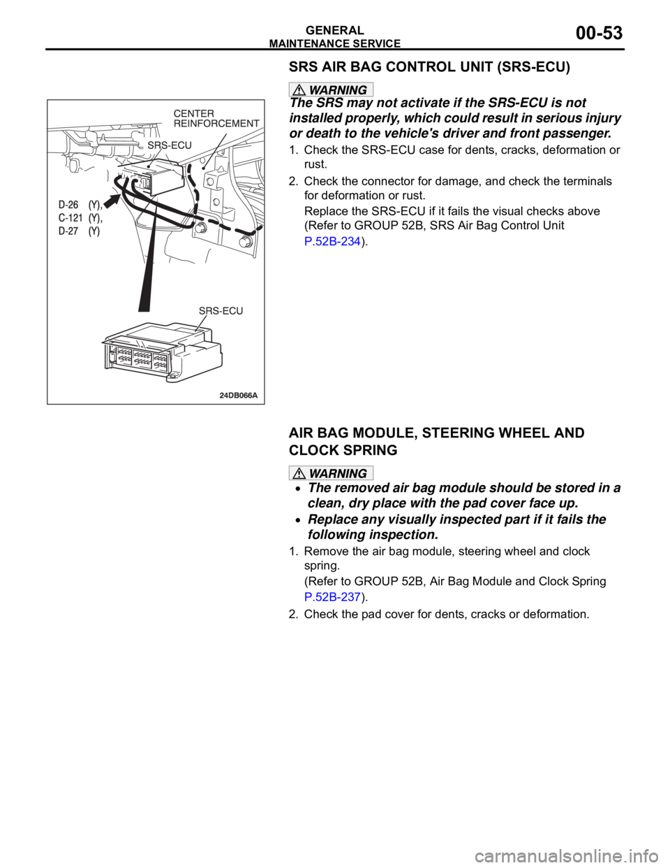
SRS AIR BAG CONTROL UNIT (SRS-ECU)
The SRS may not activate if the SRS-ECU is not
installed properly, which could result in serious injury
or death to the vehicle's driver and front passenger.
1. Check the SRS-ECU case for dents, cracks, deformation or
rust.
2. Check the connector for damage, and check the terminals
for deformation or rust.
Replace the SRS-ECU if it fails the visual checks above
(Refer to GROUP 52B, SRS Air Bag Control Unit
P.52B-234).
AIR BAG MODULE, STEERING WHEEL AND
CLOCK SPRING
The removed air bag module should be stored in a
clean, dry place with the pad cover face up.
Replace any visually inspected part if it fails the
following inspection.
1. Remove the air bag module, steering wheel and clock
spring.
(Refer to GROUP 52B, Air Bag Module and Clock Spring
P.52B-237).
2. Check the pad cover for dents, cracks or deformation.
Page 1275 of 1500
MAINTENANCE SERVICE
GENERAL00-54
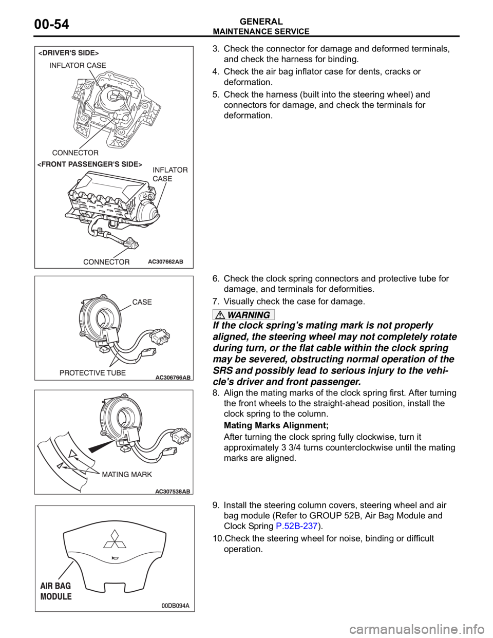
3. Check the connector for damage and deformed terminals,
and check the harness for binding.
4. Check the air bag inflator case for dents, cracks or
deformation.
5. Check the harness (built into the steering wheel) and
connectors for damage, and check the terminals for
deformation.
6. Check the clock spring connectors and protective tube for
damage, and terminals for deformities.
7. Visually check the case for damage.
If the clock spring's mating mark is not properly
aligned, the steering wheel may not completely rotate
during turn, or the flat cable within the clock spring
may be severed, obstructing normal operation of the
SRS and possibly lead to serious injury to the vehi-
cle's driver and front passenger.
8. Align the mating marks of the clock spring first. After turning
the front wheels to the straight-ahead position, install the
clock spring to the column.
Mating Marks Alignment;
After turning the clock spring fully clockwise, turn it
approximately 3 3/4 turns counterclockwise until the mating
marks are aligned.
9. Install the steering column covers, steering wheel and air
bag module (Refer to GROUP 52B, Air Bag Module and
Clock Spring P.52B-237).
10.Check the steering wheel for noise, binding or difficult
operation.
Page 1276 of 1500
MAINTENANCE SERVICE
GENERAL00-55
The SRS may not activate if any of the above compo-
nents are not installed properly, which could result in
serious injury or death to the vehicle's driver and
front passenger.
11.Check the steering wheel for excessive free play.
Replace any part if it fails visual inspection (Refer to
GROUP 52B, Air Bag Module and Clock Spring P.52B-237).
FRONT SEATBACK ASSEMBLY WITH
SIDE-AIRBAG MODULE
If any improper part is found during the following
inspection, replace the front seatback assembly
with a new one.
Dispose of the old one according to the specified
procedure (Refer to GROUP 52B, Air Bag Module
Disposal Procedures P.52B-254).
Never attempt to measure the circuit resistance of
the air bag module (squib) even if you are using
the specified tester. If the circuit resistance is mea-
sured with a tester, accidental air bag deployment
will result in serious personal injury.
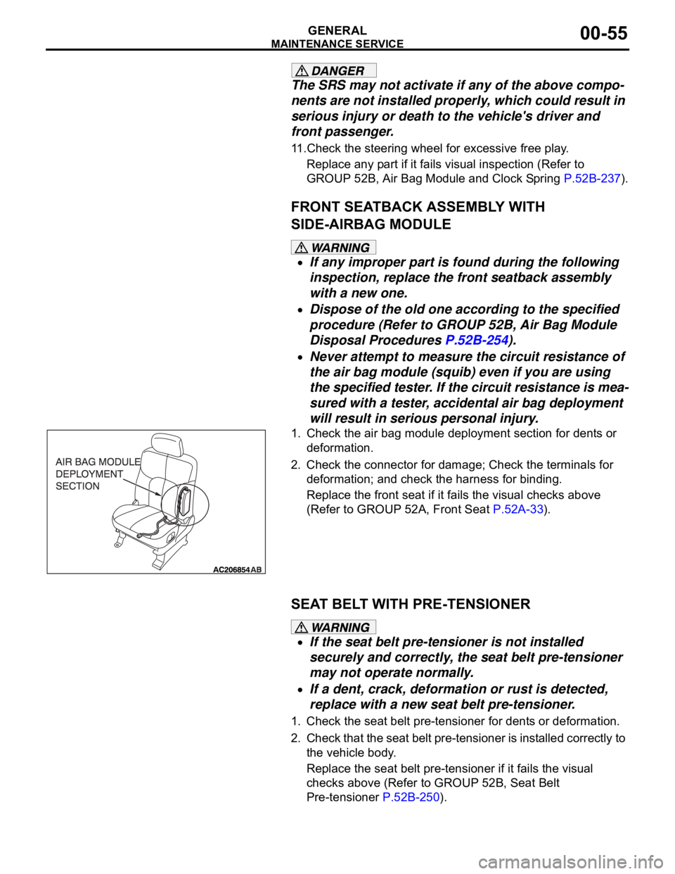
1. Check the air bag module deployment section for dents or
deformation.
2. Check the connector for damage; Check the terminals for
deformation; and check the harness for binding.
Replace the front seat if it fails the visual checks above
(Refer to GROUP 52A, Front Seat P.52A-33).
SEAT BELT WITH PRE-TENSIONER
If the seat belt pre-tensioner is not installed
securely and correctly, the seat belt pre-tensioner
may not operate normally.
If a dent, crack, deformation or rust is detected,
replace with a new seat belt pre-tensioner.
1. Check the seat belt pre-tensioner for dents or deformation.
2. Check that the seat belt pre-tensioner is installed correctly to
the vehicle body.
Replace the seat belt pre-tensioner if it fails the visual
checks above (Refer to GROUP 52B, Seat Belt
Pre-tensioner P.52B-250).
Page 1352 of 1500

AUTO-CRUISE CONTROL
ENGINE AND EMISSION CONTROL17-21
CIRCUIT OPERATION
This circuit judges the signals of each switch
("COAST/SET", "ACC/RES" and "CANCEL") of the
auto-cruise control switch. The Engine ECU detects
the state of the auto-cruise control switch by sensing
the voltages shown below.
When all switches are OFF: 4.7 5.0 volts
When the "CRUISE" (MAIN) switch is "ON": 0
0.3 volt
When the "COAST/SET" switch is ON: 2.0 2.8
volts
When the "ACC/RES" switch is ON: 3.3 4.1
volts
When the "CANCEL" switch is ON: 0.8 1.5 volts
.
DTC SET CONDITIONS
Check Condition
The "CRUISE" indicator lamp illuminates.Judgement Criteria
If the auto-cruise control switch is operated, this
DTC will be set when the Engine ECU terminal
voltage is different from the standard value.
.
TROUBLESHOOTING HINTS (THE MOST
LIKELY CAUSES FOR THIS CASE:)
Malfunction of the auto-cruise control switch.
Malfunction of the clock spring.
Damaged harness or connector.
Malfunction of the Engine ECU.
Circuit drawings
Refer to circuit diagrams GROUP-90
Refer to configuration diagrams GROUP-80
Refer to component locations GROUP-70
DIAGNOSIS
Required Special Tools:
MB991958: Diagnostic Tool (MUT-III Sub Assembly)
MB991824: V.C.I.
MB991827: MUT-III USB Cable
MB991910: MUT-III Main Harness A
MB991223: Harness Set
MB992044: ENGINE-ECU Check Harness
Page 1354 of 1500
AUTO-CRUISE CONTROL
ENGINE AND EMISSION CONTROL17-23
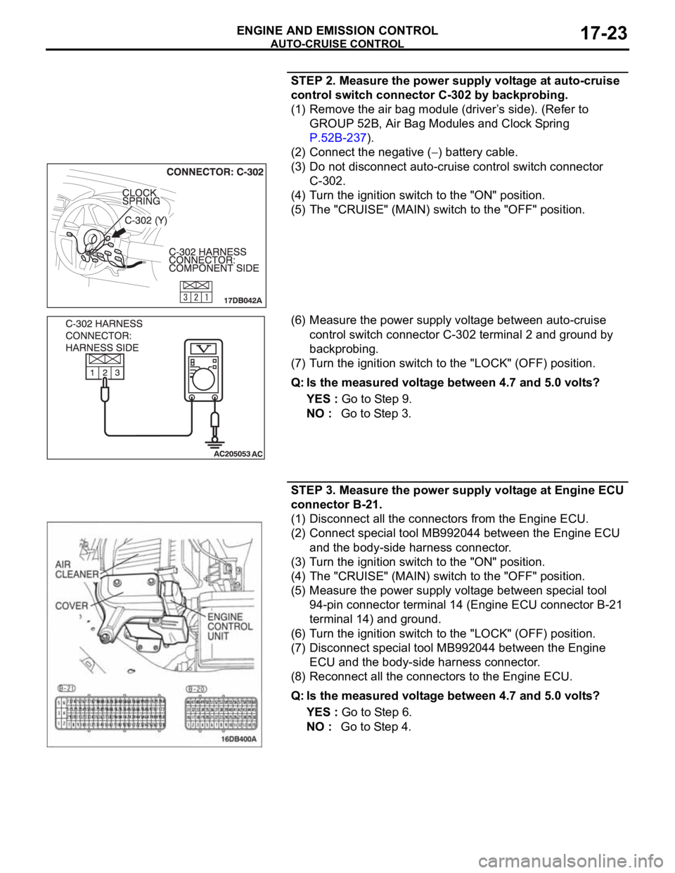
STEP 2. Measure the power supply voltage at auto-cruise
control switch connector C-302 by backprobing.
(1) Remove the air bag module (driver’s side). (Refer to
GROUP 52B, Air Bag Modules and Clock Spring
P.52B-237).
(2) Connect the negative (
) battery cable.
(3) Do not disconnect auto-cruise control switch connector
C-302.
(4) Turn the ignition switch to the "ON" position.
(5) The "CRUISE" (MAIN) switch to the "OFF" position.
(6) Measure the power supply voltage between auto-cruise
control switch connector C-302 terminal 2 and ground by
backprobing.
(7) Turn the ignition switch to the "LOCK" (OFF) position.
Q: Is the measured voltage between 4.7 and 5.0 volts?
YES : Go to Step 9.
NO : Go to Step 3.
STEP 3. Measure the power supply voltage at Engine ECU
connector B-21.
(1) Disconnect all the connectors from the Engine ECU.
(2) Connect special tool MB992044 between the Engine ECU
and the body-side harness connector.
(3) Turn the ignition switch to the "ON" position.
(4) The "CRUISE" (MAIN) switch to the "OFF" position.
(5) Measure the power supply voltage between special tool
94-pin connector terminal 14 (Engine ECU connector B-21
terminal 14) and ground.
(6) Turn the ignition switch to the "LOCK" (OFF) position.
(7) Disconnect special tool MB992044 between the Engine
ECU and the body-side harness connector.
(8) Reconnect all the connectors to the Engine ECU.
Q: Is the measured voltage between 4.7 and 5.0 volts?
YES : Go to Step 6.
NO : Go to Step 4.
Page 1355 of 1500

AUTO-CRUISE CONTROL
ENGINE AND EMISSION CONTROL17-24
STEP 4. Check Engine ECU connector B-21 for loose,
corroded or damaged terminals, or terminals pushed back
in the connector.
Q: Are the connector and terminals in good condition?
YES : Go to Step 5.
NO : Repair the faulty connector if possible or as
recommended, replace complete wiring harness.
(Refer to GROUP 00E, Harness Connector Inspection
P.00E-2). Install the air bag module (driver’s side).
(Refer to GROUP 52B, Air Bag Modules and Clock
Spring P.52B-237). Then go to Step 18.
STEP 5. Check the harness for short circuit to ground
between the Engine ECU connector B-21 terminal 14 and
the auto-cruise control switch connector C-302 terminal 2.
(1) Disconnect Engine ECU connector B-21 and measure at
the harness connector side.
(2) Turn the ignition switch to the "LOCK" (OFF) position.
(3) Measure the continuity between Engine ECU connector
B-21 terminal 14 and ground.
(4) Reconnect Engine ECU connector B-21.
Q: Is the measured continuity open circuit?
YES : Install the air bag module (driver’s side). (Refer to
GROUP 52B, Air Bag Modules and Clock Spring
P.52B-237). Then go to Step 17.
NO : Go to Step 6.
Page 1356 of 1500
AUTO-CRUISE CONTROL
ENGINE AND EMISSION CONTROL17-25
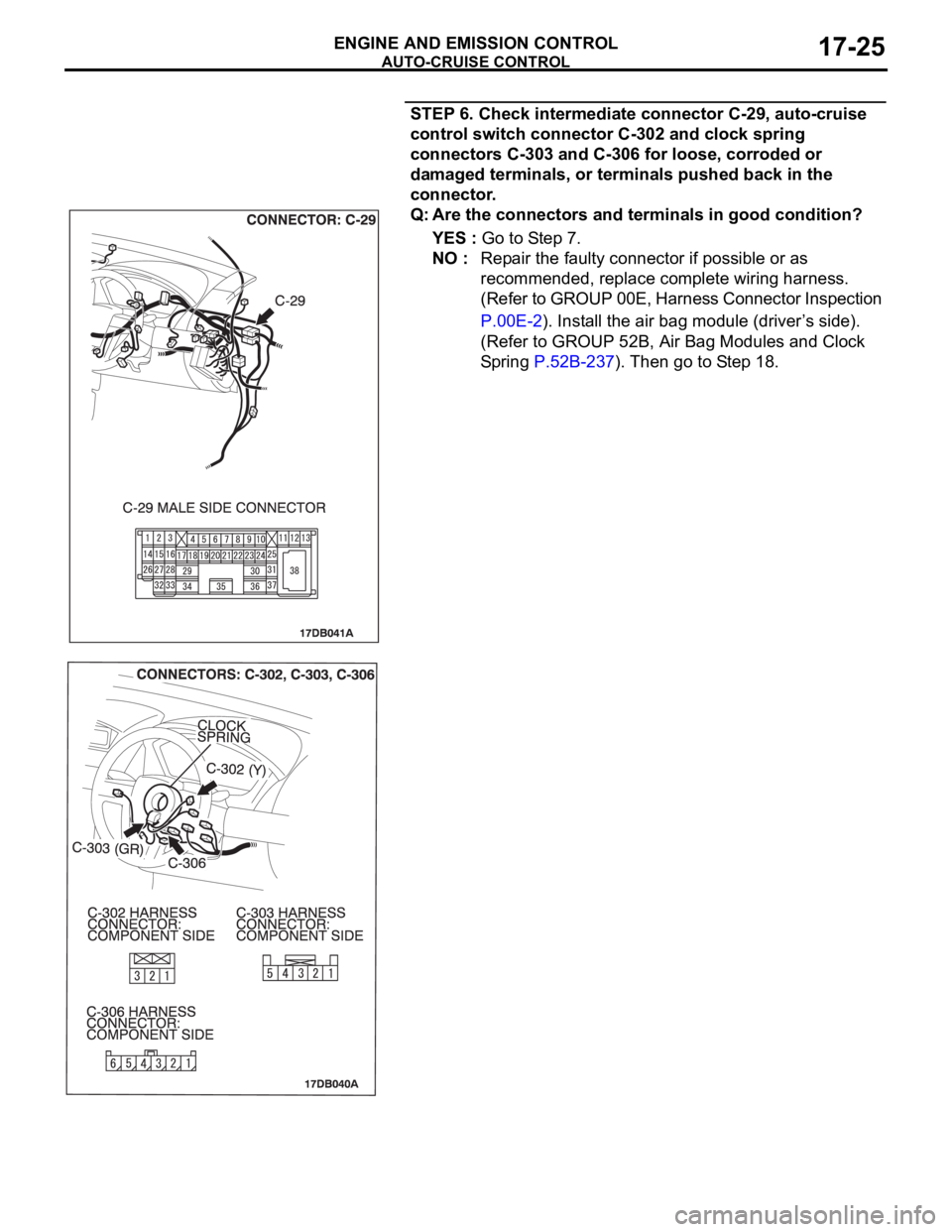
STEP 6. Check intermediate connector C-29, auto-cruise
control switch connector C-302 and clock spring
connectors C-303 and C-306 for loose, corroded or
damaged terminals, or terminals pushed back in the
connector.
Q: Are the connectors and terminals in good condition?
YES : Go to Step 7.
NO : Repair the faulty connector if possible or as
recommended, replace complete wiring harness.
(Refer to GROUP 00E, Harness Connector Inspection
P.00E-2). Install the air bag module (driver’s side).
(Refer to GROUP 52B, Air Bag Modules and Clock
Spring P.52B-237). Then go to Step 18.
Page 1357 of 1500
AUTO-CRUISE CONTROL
ENGINE AND EMISSION CONTROL17-26
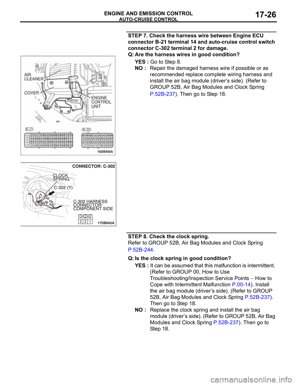
STEP 7. Check the harness wire between Engine ECU
connector B-21 terminal 14 and auto-cruise control switch
connector C-302 terminal 2 for damage.
Q: Are the harness wires in good condition?
YES : Go to Step 8.
NO : Repair the damaged harness wire if possible or as
recommended replace complete wiring harness and
install the air bag module (driver’s side). (Refer to
GROUP 52B, Air Bag Modules and Clock Spring
P.52B-237). Then go to Step 18.
STEP 8. Check the clock spring.
Refer to GROUP 52B, Air Bag Modules and Clock Spring
P.52B-244.
Q: Is the clock spring in good condition?
YES : It can be assumed that this malfunction is intermittent.
(Refer to GROUP 00, How to Use
Troubleshooting/Inspection Service Points
How to
Cope with Intermittent Malfunction P.00-14). Install
the air bag module (driver’s side). (Refer to GROUP
52B, Air Bag Modules and Clock Spring P.52B-237).
Then go to Step 18.
NO : Replace the clock spring and install the air bag
module (driver’s side). (Refer to GROUP 52B, Air Bag
Modules and Clock Spring P.52B-237). Then go to
Step 18.
Page 1359 of 1500
AUTO-CRUISE CONTROL
ENGINE AND EMISSION CONTROL17-28
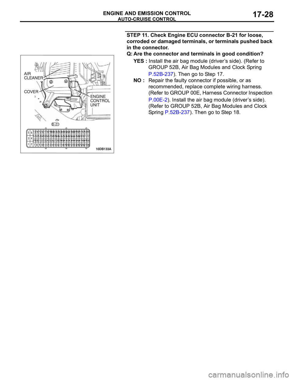
STEP 11. Check Engine ECU connector B-21 for loose,
corroded or damaged terminals, or terminals pushed back
in the connector.
Q: Are the connector and terminals in good condition?
YES : Install the air bag module (driver’s side). (Refer to
GROUP 52B, Air Bag Modules and Clock Spring
P.52B-237). Then go to Step 17.
NO : Repair the faulty connector if possible, or as
recommended, replace complete wiring harness.
(Refer to GROUP 00E, Harness Connector Inspection
P.00E-2). Install the air bag module (driver’s side).
(Refer to GROUP 52B, Air Bag Modules and Clock
Spring P.52B-237). Then go to Step 18.