seat memory MITSUBISHI 380 2005 User Guide
[x] Cancel search | Manufacturer: MITSUBISHI, Model Year: 2005, Model line: 380, Model: MITSUBISHI 380 2005Pages: 1500, PDF Size: 47.87 MB
Page 521 of 1500

FRONT SEAT ASSEMBLY
INTERIOR52A-32
CIRCUIT DIAGRAMS:
Refer to circuit diagrams GROUP-90
Refer to configuration diagrams GROUP-80
NOTE: Check connectors and terminals for damage or
loose connections at the seat harness and all supply
circuits connections to seat. Repair or replace wiring
harness if damaged.
ERASING DIAGNOSTIC TROUBLE CODES (DTC’s)
The Memory Seat Controller will temporarily store DTC’s when
incorrect operating conditions are detected. The DTC’s are
self-clearing as soon as each fault condition is rectified and
returns to normal operating function. LED FLASH
SEQUENCEFAULT CONDITION
DETECTEDPOSSIBLE CAUSE
2 then 1 No fore lift motor sensor Connection at motor sensor
or open/ short circuit in
wiring harness.
2 then 2 No aft lift motor sensor Connection at motor sensor
or open/ short circuit in
wiring harness.
2 then 3 No track motor sensor Connection at motor sensor
or open/ short circuit in
wiring harness.
2 then 4 No pedal motor sensor Connection at motor sensor
or open/ short circuit in
wiring harness.
2 then 5 No recliner motor sensor Connection at motor sensor
or open/ short circuit in
wiring harness.
2 then 6 No lumbar motor sensor Connection at motor sensor
or open/ short circuit in
wiring harness.
3 then 1 Button stuck MEMORY Button switch cap stuck on
side cover
3 then 2 Manual Button stuck position Button switch cap stuck on
side cover
6 then 3 Power relay welded shut Grime on contact
Page 525 of 1500

Page 567 of 1500
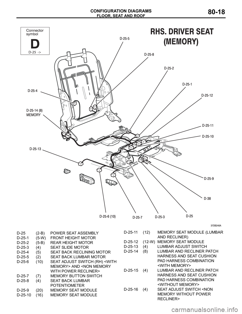
FLOOR, SEAT AND ROOF
CONFIGURATION DIAGRAMS80-18
D-25 (2-B) POWER SEAT ASSEMBLY
D-25-1 (5-W) FRONT HEIGHT MOTOR
D-25-2 (5-B) REAR HEIGHT MOTOR
D-25-3 (4) SEAT SLIDE MOTOR
D-25-4 (5) SEAT BACK RECLINING MOTOR
D-25-5 (2) SEAT BACK LUMBAR MOTOR
D-25-6 (10) SEAT ADJUST SWITCH (RH)
D-25-7 (7) MEMORY BUTTON SWITCH
D-25-8 (4) SEAT BACK LUMBAR
POTENTIOMETER
D-25-9 (20) MEMORY SEAT MODULE
D-25-10 (16) MEMORY SEAT MODULED-25-11 (12) MEMORY SEAT MODULE (LUMBAR
AND RECLINER)
D-25-12 (12-W) MEMORY SEAT MODULE
D-25-13 (4) LUMBAR ADJUST SWITCH
D-25-14 (8) LUMBAR AND RECLINER PATCH
HARNESS AND SEAT CUSHION
PAD HARNESS COMBINATION
D-25-15 (4) LUMBAR AND RECLINER PATCH
HARNESS AND SEAT CUSHION
PAD HARNESS COMBINATION
D-25-16 (4) SEAT ADJUST SWITCH
RECLINER>
Page 571 of 1500
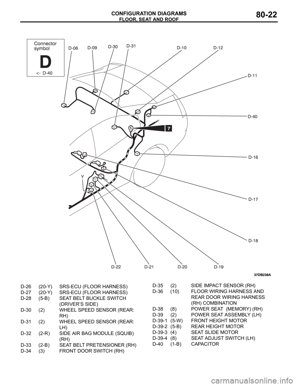
FLOOR, SEAT AND ROOF
CONFIGURATION DIAGRAMS80-22
D-26 (20-Y) SRS-ECU (FLOOR HARNESS)
D-27 (20-Y) SRS-ECU (FLOOR HARNESS)
D-28 (5-B) SEAT BELT BUCKLE SWITCH
(DRIVER’S SIDE)
D-30 (2) WHEEL SPEED SENSOR (REAR:
RH)
D-31 (2) WHEEL SPEED SENSOR (REAR:
LH)
D-32 (2-R) SIDE AIR BAG MODULE (SQUIB)
(RH)
D-33 (2-B) SEAT BELT PRETENSIONER (RH)
D-34 (3) FRONT DOOR SWITCH (RH)D-35 (2) SIDE IMPACT SENSOR (RH)
D-36 (10) FLOOR WIRING HARNESS AND
REAR DOOR WIRING HARNESS
(RH) COMBINATION
D-38 (8) POWER SEAT (MEMORY) (RH)
D-39 (2) POWER SEAT ASSEMBLY (LH)
D-39-1 (5-W) FRONT HEIGHT MOTOR
D-39-2 (5-B) REAR HEIGHT MOTOR
D-39-3 (4) SEAT SLIDE MOTOR
D-39-4 (8) SEAT ADJUST SWITCH (LH)
D-40 (1-B) CAPACITOR
Page 579 of 1500
CIRCUIT DIAGRAMS90-2
AUTOMATIC AIR CONDITIONING
SYSTEM . . . . . . . . . . . . . . . . . . . . . . .90-71
WINDSHIELD WIPER AND WASHER90-75
REAR WINDOW DEFOGGER . . . . . .90-78
REMOTE CONTROLLED MIRROR . .90-79
AUDIO SYSTEM . . . . . . . . . . . . . . . .90-80
ACCESSORY SOCKET . . . . . . . . . . .90-82
CLOCK DISPLAY . . . . . . . . . . . . . . .90-83
MULTI-CENTER DISPLAY . . . . . . . .90-84
SUNROOF . . . . . . . . . . . . . . . . . . . . .90-87
AUTO-CRUISE CONTROL SYSTEM90-89
ANTI-LOCK BRAKING SYSTEM (ABS)
ANTI-LOCK BRAKING SYSTEM (ABS)
SYSTEM (SRS) . . . . . . . . . . . . . . . . . .90-99
ENGINE IMMOBILISER SYSTEM . . .90-103
POWER SEAT WITH MEMORY
(DRIVER). . . . . . . . . . . . . . . . . . . . . . .90-104
POWER SEAT (8-WAY)
(DRIVER AND PASSENGER) . . . . . .90-106
POWER SEAT [(6-WAY) DRIVER] . .90-108
FORGOTTEN KEY PREVENTION
FUNCTION . . . . . . . . . . . . . . . . . . . . .90-109
LIGHTING MONITOR TONE ALARM90-111
IGNITION KEY REMINDER TONE
ALARM . . . . . . . . . . . . . . . . . . . . . . . .90-112
SEAT BELT WARNING TONE
ALARM . . . . . . . . . . . . . . . . . . . . . . . .90-113
DOOR AJAR WARNING TONE
ALARM . . . . . . . . . . . . . . . . . . . . . . . .90-115
RHEOSTAT . . . . . . . . . . . . . . . . . . . . .90-118
CONTROLLER AREA NETWORK
(CAN) . . . . . . . . . . . . . . . . . . . . . . . . .90-119
Page 681 of 1500
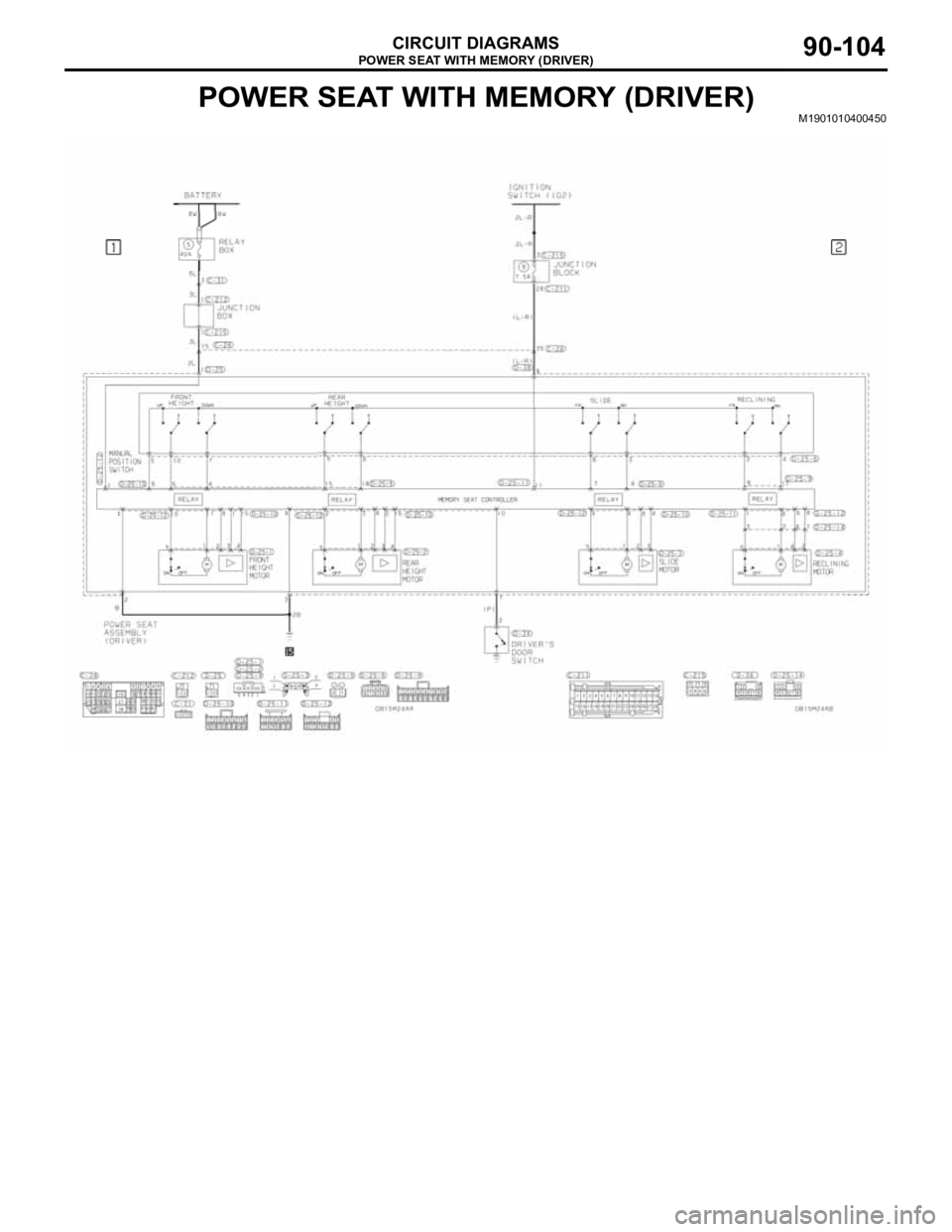
POWER SEAT WITH MEMORY (DRIVER)
CIRCUIT DIAGRAMS90-104
POWER SEAT WITH MEMORY (DRIVER)M1901010400450
Page 682 of 1500
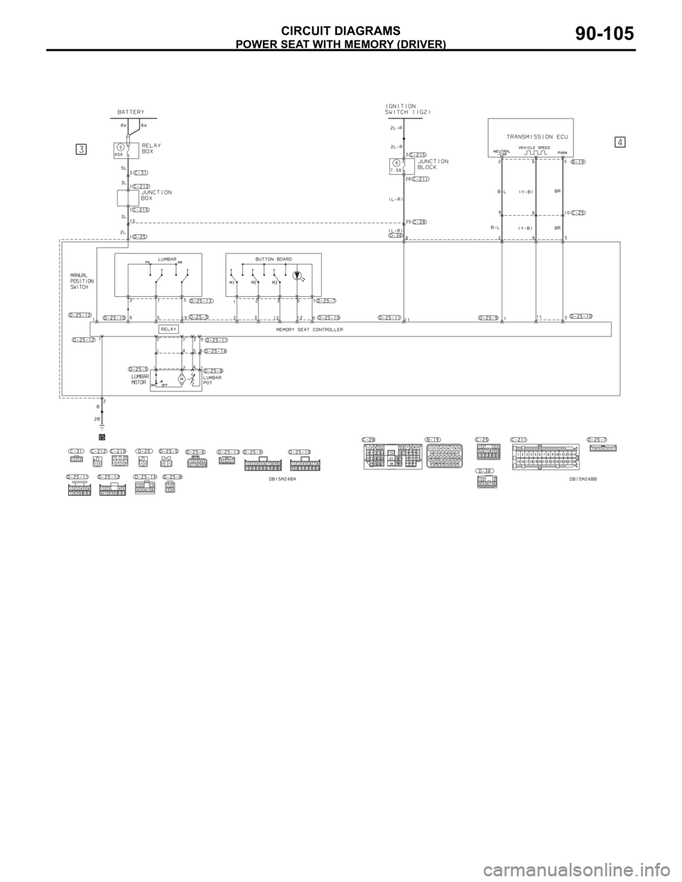
POWER SEAT WITH MEMORY (DRIVER)
CIRCUIT DIAGRAMS90-105