Ignition MITSUBISHI 380 2005 Workshop Manual
[x] Cancel search | Manufacturer: MITSUBISHI, Model Year: 2005, Model line: 380, Model: MITSUBISHI 380 2005Pages: 1500, PDF Size: 47.87 MB
Page 1316 of 1500

TRACTION CONTROL SYSTEM (TCL) DIAGNOSIS
TRACTION CONTROL SYSTEM (TCL)13C-37
ACTUATOR TEST REFERENCE TABLEM1136003600067
NOTE: If the ABS-8 ECU or the active wheel
speed sensor are disconnected, or if the wiring is
an open/ short circuit, the ABS 8 ECU will shut
off power supply to the respective wheel speed
sensor. All other wheel speed sensors will oper-
ate normally. To restore the power supply, the
ignition switch must be turned to the "OFF" posi-
tion then to the "ON" position again.The diagnostic tool activates the following actuators
for testing. (Refer to P.13C-3).
NOTE: Since the TCL is controlled with the same ABS/TCL-ECU used to control the ABS, the FL, FR, RL or
RR Wheel ABS Drive testing items (No.01 to 04) used only for the ABS also appear. MUT-III
DIAGNOSTIC TOOL
DISPLAYITEM NO. CHECK ITEM PARTS TO BE ACTIVATED
FL wheel ABS Drive* 01 Solenoid valve for front left wheel Solenoid valves and pump
motors in the hydraulic unit
(simple inspection mode) FR wheel ABS Drive* 02 Solenoid valve for front right wheel
RL wheel ABS Drive* 03 Solenoid valve for rear left wheel
RR wheel ABS
Drive*04 Solenoid valve for rear right wheel
Engine TCL Drive 09 TCL operation check Outputs the engine torque
control signal (engine torque =
0) to PCM for three seconds.
Page 1317 of 1500
TRACTION CONTROL SYSTEM (TCL) DIAGNOSIS
TRACTION CONTROL SYSTEM (TCL)13C-38
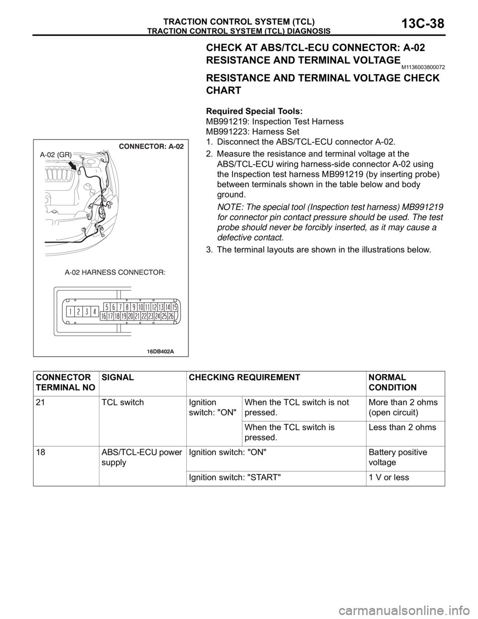
CHECK AT ABS/TCL-ECU CONNECTOR: A-02
RESISTANCE AND TERMINAL VOLTAGE
M1136003800072
RESISTANCE AND TERMINAL VOLTAGE CHECK
CHART
.
Required Special Tools:
MB991219: Inspection Test Harness
MB991223: Harness Set
1. Disconnect the ABS/TCL-ECU connector A-02.
2. Measure the resistance and terminal voltage at the
ABS/TCL-ECU wiring harness-side connector A-02 using
the Inspection test harness MB991219 (by inserting probe)
between terminals shown in the table below and body
ground.
NOTE: The special tool (Inspection test harness) MB991219
for connector pin contact pressure should be used. The test
probe should never be forcibly inserted, as it may cause a
defective contact.
3. The terminal layouts are shown in the illustrations below.
CONNECTOR
TERMINAL NOSIGNAL CHECKING REQUIREMENT NORMAL
CONDITION
21 TCL switch Ignition
switch: "ON" When the TCL switch is not
pressed.More than 2 ohms
(open circuit)
When the TCL switch is
pressed.Less than 2 ohms
18 ABS/TCL-ECU power
supplyIgnition switch: "ON" Battery positive
voltage
Ignition switch: "START" 1 V or less
Page 1318 of 1500
TRACTION CONTROL SYSTEM (TCL) DIAGNOSIS
TRACTION CONTROL SYSTEM (TCL)13C-39
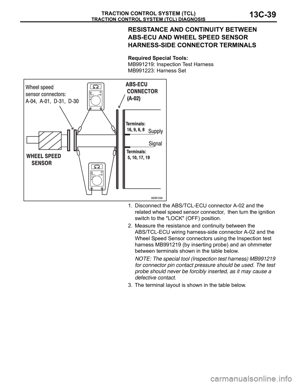
RESISTANCE AND CONTINUITY BETWEEN
ABS-ECU AND WHEEL SPEED SENSOR
HARNESS-SIDE CONNECTOR TERMINALS
.
Required Special Tools:
MB991219: Inspection Test Harness
MB991223: Harness Set
1. Disconnect the ABS/TCL-ECU connector A-02 and the
related wheel speed sensor connector, then turn the ignition
switch to the "LOCK" (OFF) position.
2. Measure the resistance and continuity between the
ABS/TCL-ECU wiring harness-side connector A-02 and the
Wheel Speed Sensor connectors using the Inspection test
harness MB991219 (by inserting probe) and an ohmmeter
between terminals shown in the table below.
NOTE: The special tool (Inspection test harness) MB991219
for connector pin contact pressure should be used. The test
probe should never be forcibly inserted, as it may cause a
defective contact.
3. The terminal layout is shown in the table below.
Page 1320 of 1500
TRACTION CONTROL SYSTEM (TCL) DIAGNOSIS
TRACTION CONTROL SYSTEM (TCL)13C-41
VOLTAGE AND SIGNAL CHECK AT ABS-ECU
(A-02) USING OSCILLOSCOPE
NOTE: If the ABS-8 ECU or the active wheel speed
sensor are disconnected, or if the wiring is an open/
short circuit, the ABS 8 ECU will shut off power sup-
ply to the respective wheel speed sensor. All other
wheel speed sensors will operate normally. To
restore the power supply, the ignition switch must be
turned to the "OFF" position then to the "ON" position
again..
WHEEL SPEED SENSOR AIR GAP:
Sensor air gap: (0.2mm - 0.85mm).
.
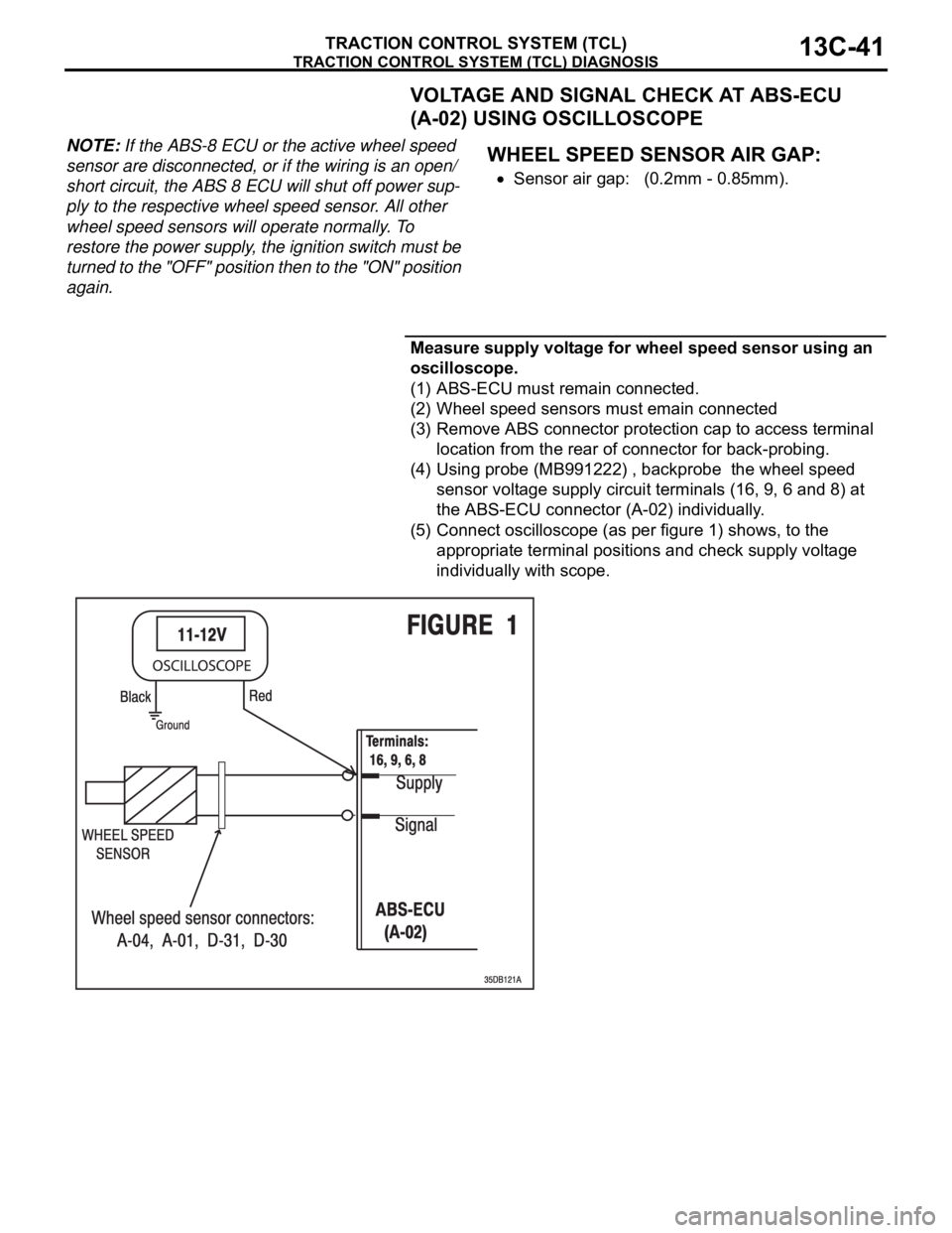
Measure supply voltage for wheel speed sensor using an
oscilloscope.
(1) ABS-ECU must remain connected.
(2) Wheel speed sensors must emain connected
(3) Remove ABS connector protection cap to access terminal
location from the rear of connector for back-probing.
(4) Using probe (MB991222) , backprobe the wheel speed
sensor voltage supply circuit terminals (16, 9, 6 and 8) at
the ABS-ECU connector (A-02) individually.
(5) Connect oscilloscope (as per figure 1) shows, to the
appropriate terminal positions and check supply voltage
individually with scope.
Page 1321 of 1500

TRACTION CONTROL SYSTEM (TCL) DIAGNOSIS
TRACTION CONTROL SYSTEM (TCL)13C-42
Connect oscilloscope to FL sensor signal terminal (16)
at ABS-ECU (A-02)
Connect oscilloscope to FR sensor signal terminal (9) at
ABS-ECU (A-02)
Connect oscilloscope to RL sensor signal terminal (6) at
ABS-ECU (A-02)
Connect oscilloscope to RR sensor signal terminal (8) at
ABS-ECU (A-02)
(6) Turn the ignition switch to the "ON" position.
Page 1323 of 1500
TRACTION CONTROL SYSTEM (TCL) DIAGNOSIS
TRACTION CONTROL SYSTEM (TCL)13C-44
Connect oscilloscope to FL sensor signal terminal (5) at
ABS-ECU (A-02)
Connect oscilloscope to FR sensor signal terminal (10)
at ABS-ECU (A-02)
Connect oscilloscope to RL sensor signal terminal (17)
at ABS-ECU (A-02)
Connect oscilloscope to RR sensor signal terminal (19)
at ABS-ECU (A-02)
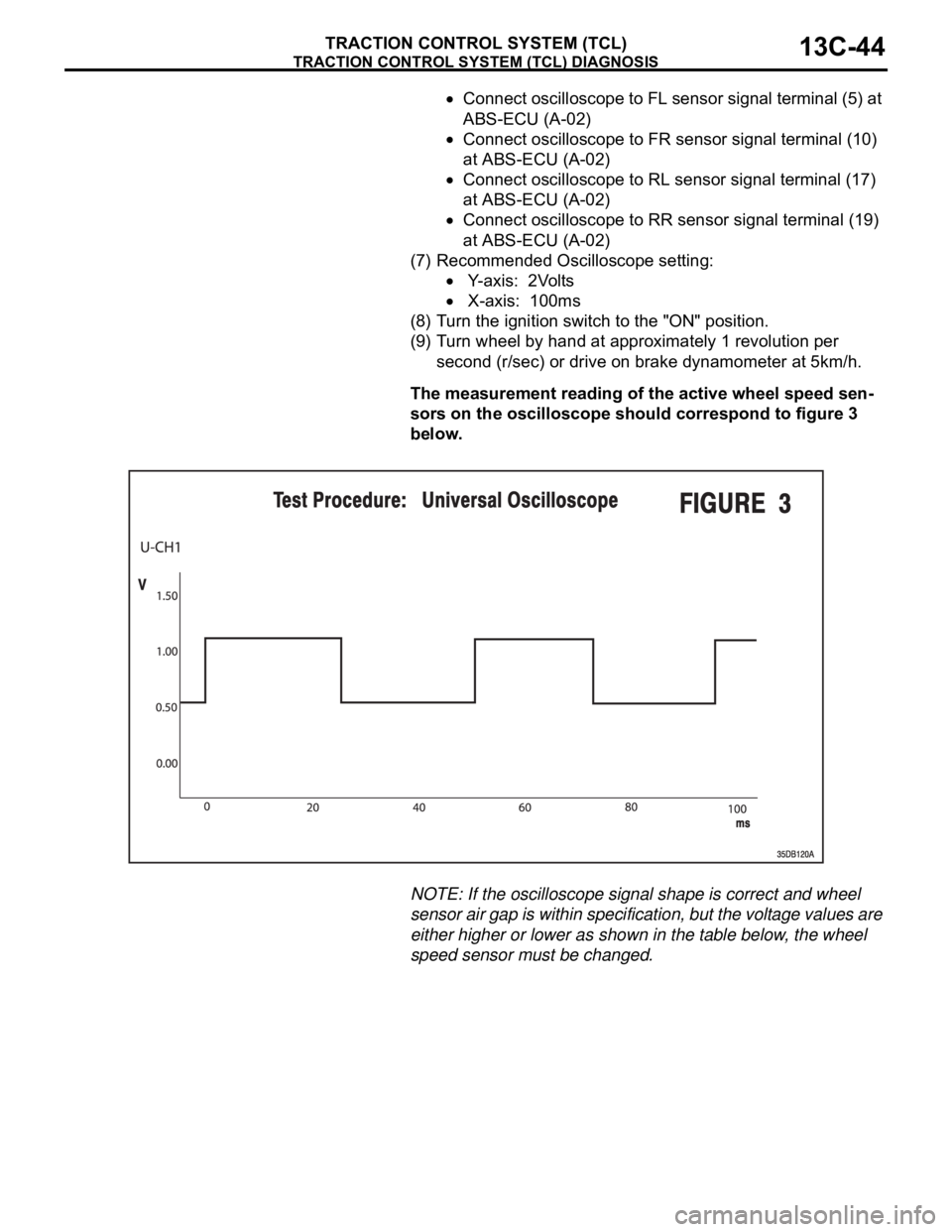
(7) Recommended Oscilloscope setting:
Y-axis: 2Volts
X-axis: 100ms
(8) Turn the ignition switch to the "ON" position.
(9) Turn wheel by hand at approximately 1 revolution per
second (r/sec) or drive on brake dynamometer at 5km/h.
The measurement reading of the active wheel speed sen-
sors on the oscilloscope should correspond to figure 3
below.
NOTE: If the oscilloscope signal shape is correct and wheel
sensor air gap is within specification, but the voltage values are
either higher or lower as shown in the table below, the wheel
speed sensor must be changed.
Page 1326 of 1500
ON-VEHICLE SERVICE
TRACTION CONTROL SYSTEM (TCL)13C-47
ON-VEHICLE SERVICE
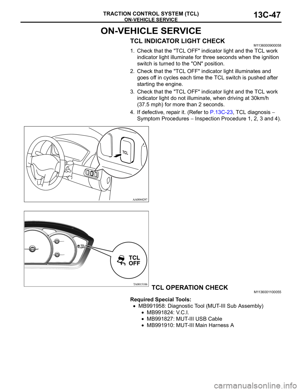
TCL INDICATOR LIGHT CHECKM1136000900058
1. Check that the "TCL OFF" indicator light and the TCL work
indicator light illuminate for three seconds when the ignition
switch is turned to the "ON" position.
2. Check that the "TCL OFF" indicator light illuminates and
goes off in cycles each time the TCL switch is pushed after
starting the engine.
3. Check that the "TCL OFF" indicator light and the TCL work
indicator light do not illuminate, when driving at 30km/h
(37.5 mph) for more than 2 seconds.
4. If defective, repair it. (Refer to P.13C-23, TCL diagnosis
Symptom Procedures
Inspection Procedure 1, 2, 3 and 4).
TCL OPERATION CHECKM1136001100055
Required Special Tools:
MB991958: Diagnostic Tool (MUT-III Sub Assembly)
MB991824: V.C.I.
MB991827: MUT-III USB Cable
MB991910: MUT-III Main Harness A
Page 1327 of 1500
ON-VEHICLE SERVICE
TRACTION CONTROL SYSTEM (TCL)13C-48
To prevent damage to diagnostic tool MB991958, always
turn the ignition switch to the "LOCK" (OFF) position
before connecting or disconnecting diagnostic tool
MB991958.
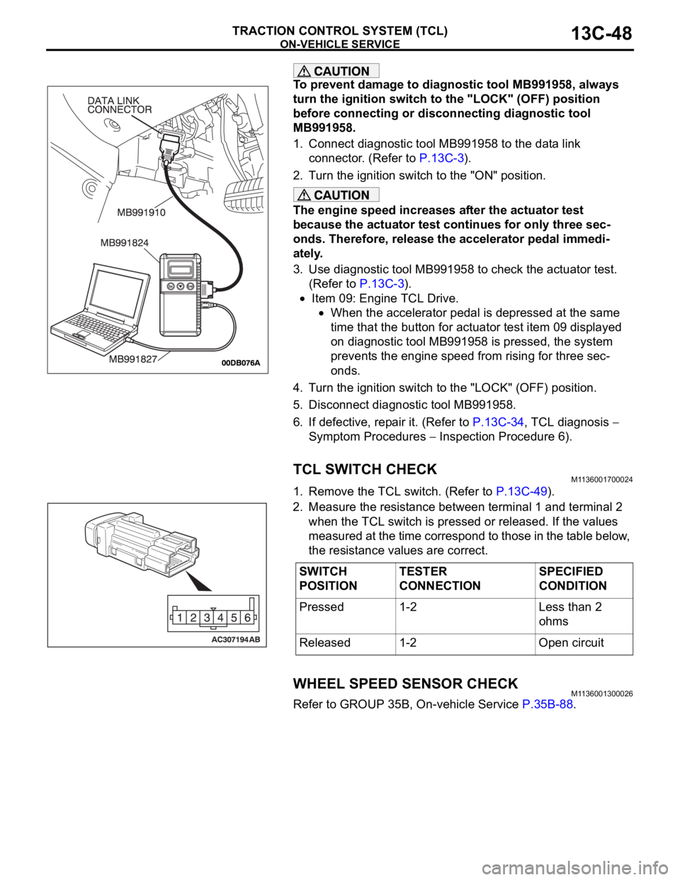
1. Connect diagnostic tool MB991958 to the data link
connector. (Refer to P.13C-3).
2. Turn the ignition switch to the "ON" position.
The engine speed increases after the actuator test
because the actuator test continues for only three sec-
onds. Therefore, release the accelerator pedal immedi-
ately.
3. Use diagnostic tool MB991958 to check the actuator test.
(Refer to P.13C-3).
Item 09: Engine TCL Drive.
When the accelerator pedal is depressed at the same
time that the button for actuator test item 09 displayed
on diagnostic tool MB991958 is pressed, the system
prevents the engine speed from rising for three sec-
onds.
4. Turn the ignition switch to the "LOCK" (OFF) position.
5. Disconnect diagnostic tool MB991958.
6. If defective, repair it. (Refer to P.13C-34, TCL diagnosis
Symptom Procedures
Inspection Procedure 6).
TCL SWITCH CHECKM1136001700024
1. Remove the TCL switch. (Refer to P.13C-49).
2. Measure the resistance between terminal 1 and terminal 2
when the TCL switch is pressed or released. If the values
measured at the time correspond to those in the table below,
the resistance values are correct.
WHEEL SPEED SENSOR CHECKM1136001300026
Refer to GROUP 35B, On-vehicle Service P.35B-88.
SWITCH
POSITIONTESTER
CONNECTIONSPECIFIED
CONDITION
Pressed 1-2 Less than 2
ohms
Released 1-2 Open circuit
Page 1336 of 1500
ENGINE CONTROL
ENGINE AND EMISSION CONTROL17-5
DIAGNOSIS
Required Special Tools:
MB991958: Diagnostic Tool (MUT-III Sub Assembly)
MB991824: Vehicle Communication Interface (V.C.I.)
MB991827: MUT-III USB Cable
MB991910: MUT-III Main Harness A
STEP 1. Using Diagnostic Tool MB991958, read the
diagnostic trouble code (DTC).
To prevent damage to Diagnostic Tool MB991958, always
turn the ignition switch to the "LOCK" (OFF) position
before connecting or disconnecting Diagnostic Tool
MB991958.
(1) Ensure that the ignition switch is at the "LOCK" (OFF)
position.
(2) Start up the personal computer.
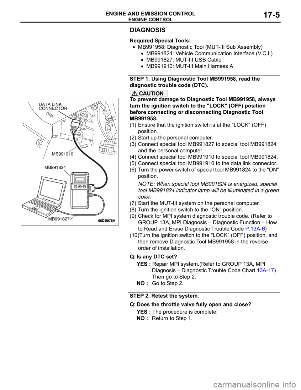
(3) Connect special tool MB991827 to special tool MB991824
and the personal computer.
(4) Connect special tool MB991910 to special tool MB991824.
(5) Connect special tool MB991910 to the data link connector.
(6) Turn the power switch of special tool MB991824 to the "ON"
position.
NOTE: When special tool MB991824 is energized, special
tool MB991824 indicator lamp will be illuminated in a green
color.
(7) Start the MUT-III system on the personal computer.
(8) Turn the ignition switch to the "ON" position.
(9) Check for MPI system diagnostic trouble code. (Refer to
GROUP 13A, MPI Diagnosis
Diagnostic Function How
to Read and Erase Diagnostic Trouble Code P.13A-6) .
(10)Turn the ignition switch to the "LOCK" (OFF) position, and
then remove Diagnostic Tool MB991958 in the reverse
order of installation.
Q: Is any DTC set?
YES : Repair MPI system.(Refer to GROUP 13A, MPI
Diagnosis
Diagnostic Trouble Code Chart 13A-17) .
Then go to Step 2.
NO : Go to Step 2.
STEP 2. Retest the system.
Q: Does the throttle valve fully open and close?
YES : The procedure is complete.
NO : Return to Step 1.
Page 1338 of 1500
ENGINE CONTROL
ENGINE AND EMISSION CONTROL17-7
STEP 2. Using Diagnostic Tool MB991958, read the
diagnostic trouble code (DTC).
To prevent damage to Diagnostic Tool MB991958, always
turn the ignition switch to the "LOCK" (OFF) position
before connecting or disconnecting Diagnostic Tool
MB991958.
(1) Ensure that the ignition switch is at the "LOCK" (OFF)
position.
(2) Start up the personal computer.
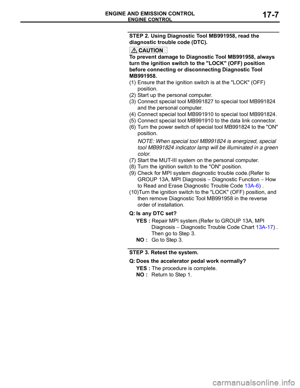
(3) Connect special tool MB991827 to special tool MB991824
and the personal computer.
(4) Connect special tool MB991910 to special tool MB991824.
(5) Connect special tool MB991910 to the data link connector.
(6) Turn the power switch of special tool MB991824 to the "ON"
position.
NOTE: When special tool MB991824 is energized, special
tool MB991824 indicator lamp will be illuminated in a green
color.
(7) Start the MUT-III system on the personal computer.
(8) Turn the ignition switch to the "ON" position.
(9) Check for MPI system diagnostic trouble code.(Refer to
GROUP 13A, MPI Diagnosis
Diagnostic Function How
to Read and Erase Diagnostic Trouble Code 13A-6) .
(10)Turn the ignition switch to the "LOCK" (OFF) position, and
then remove Diagnostic Tool MB991958 in the reverse
order of installation.
Q: Is any DTC set?
YES : Repair MPI system.(Refer to GROUP 13A, MPI
Diagnosis
Diagnostic Trouble Code Chart 13A-17) .
Then go to Step 3.
NO : Go to Step 3.
STEP 3. Retest the system.
Q: Does the accelerator pedal work normally?
YES : The procedure is complete.
NO : Return to Step 1.