diagnostic menu MITSUBISHI 380 2005 Repair Manual
[x] Cancel search | Manufacturer: MITSUBISHI, Model Year: 2005, Model line: 380, Model: MITSUBISHI 380 2005Pages: 1500, PDF Size: 47.87 MB
Page 421 of 1500

INPUT SIGNAL PROCEDURES
SIMPLIFIED WIRING SYSTEM (SWS)54B-421
STEP 1. Use diagnostic tool MB991958 to select "ECU
COMM Check" on the SWS monitor display.
Check the column-ECU.
To prevent damage to diagnostic tool MB991958, always
turn the ignition switch to the "LOCK" (OFF) position
before connecting or disconnecting diagnostic tool
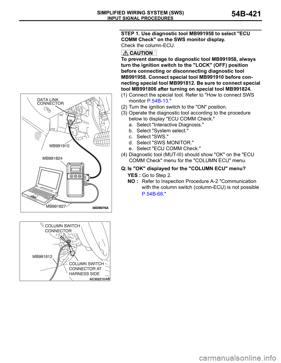
MB991958. Connect special tool MB991910 before con-
necting special tool MB991812. Be sure to connect special
tool MB991806 after turning on special tool MB991824.
(1) Connect the special tool. Refer to "How to connect SWS
monitor P.54B-13."
(2) Turn the ignition switch to the "ON" position.
(3) Operate the diagnostic tool according to the procedure
below to display "ECU COMM Check."
a. Select "Interactive Diagnosis."
b. Select "System select."
c. Select "SWS."
d. Select "SWS MONITOR."
e. Select "ECU COMM Check."
(4) Diagnostic tool (MUT-III) should show "OK" on the "ECU
COMM Check" menu for the "COLUMN ECU" menu.
Q: Is "OK" displayed for the "COLUMN ECU" menu?
YES : Go to Step 2.
NO : Refer to Inspection Procedure A-2 "Communication
with the column switch (column-ECU) is not possible
P.54B-68."
Page 424 of 1500

INPUT SIGNAL PROCEDURES
SIMPLIFIED WIRING SYSTEM (SWS)54B-424
STEP 1. Use diagnostic tool MB991958 to select "ECU
COMM Check" on the SWS monitor display.
Check the column-ECU.
To prevent damage to diagnostic tool MB991958, always
turn the ignition switch to the "LOCK" (OFF) position
before connecting or disconnecting diagnostic tool
MB991958. Connect special tool MB991910 before con-
necting special tool MB991812. Be sure to connect special
tool MB991806 after turning on special tool MB991824.
(1) Connect the special tool. Refer to "How to connect SWS
monitor P.54B-13."
(2) Turn the ignition switch to the "ON" position.
(3) Operate the diagnostic tool according to the procedure
below to display "ECU COMM Check."
a. Select "Interactive Diagnosis."
b. Select "System select."
c. Select "SWS."
d. Select "SWS MONITOR."
e. Select "ECU COMM Check."
(4) Diagnostic tool (MUT-III) should show "OK" on the "ECU
COMM Check" menu for the "COLUMN ECU" menu.
Q: Is "OK" displayed for the "COLUMN ECU" menu?
YES : Go to Step 2.
NO : Refer to Inspection Procedure A-2 "Communication
with the column switch (column-ECU) is not possible
P.54B-68."
Page 1244 of 1500

PRECAUTIONS BEFORE SERVICE
GENERAL00-23
HOW TO PERFORM VEHICLE IDENTIFICATION
NUMBER (VIN) WRITING
M1001011400063
The Vehicle Identification Number (VIN) is stored in the ECU by
the vehicle manufacture. If the VIN to be stored in the ECU is
eliminated fraudulently, the Malfunction Indicator Lamp (Check
Engine Lamp) illuminates and Diagnostic Trouble Code (DTC)
No.P0630 (VIN malfunction) is shown. When the ECU is
replaced, and entry of the VIN necessary due to DTC No.
P0630 (VIN malfunction). Enter the VIN in accordance with the
procedure as follows:
.
WRITING PROCEDURE
Required Special Tools:
Diagnostic Tool (MUT-III)
MB991824: V.C.I.
MB991827: MUT-III USB Cable
MB991910: MUT-III Main Harness A (BLUE)
To prevent damage to DIAGNOSTIC TOOL (MUT-III), always
turn the ignition switch to the "LOCK" (OFF) position
before connecting or disconnecting.
1. Connect Diagnostic Tool to the data link connector.
2. Turn the ignition switch to the "ON" position.
3. Confirm DTC No.P0630 (EEPROM malfunction) is not
shown.
NOTE: When DTC No. P0630 (EEPROM malfunction) is
shown, the VIN cannot be stored even if entered. Therefore,
the troubleshooting is performed when this DTC is shown.
4. Select "Coding" form the menu screen.
5. Select "VIN writing" form the menu screen.
6. Enter the VIN.
7. After entry of the VIN, turn the ignition switch to the "LOCK"
(OFF) position. After ten seconds or more passed, turn to
the "ON" position again.
8. Confirm DTC No.P0630 (VIN malfunction) is not shown.
NOTE: When DTC No.P0630 (VIN malfunction) is shown,
enter the VIN again because that would be not appropriate.
Page 1260 of 1500

MAINTENANCE SERVICE
GENERAL00-39
7. DRIVE BELTS (FOR ALTERNATOR, POWER
STEERING PUMP AND AIR CONDITIONING)
(CHECK)
M1001008700031
ALTERNATOR DRIVE BELT TENSION CHECK
<3.8L ENGINE>
.
WHEN USING DIAGNOSTIC TOOL (MUT-III)
Required Special Tools:
MB991668: Belt Tension Meter Set
Diagnostic Tool (MUT-III)
MB991824: Vehicle Communication Interface (V.C.I.)
MB991910: MUT-III Main Harness A (BLUE)
To prevent damage to DIAGNOSTIC TOOL (MUT-III), always
turn the ignition switch to the "LOCK" (OFF) position
before connecting or disconnecting.
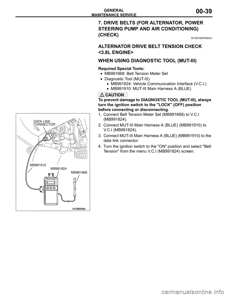
1. Connect Belt Tension Meter Set (MB991668) to V.C.I
(MB991824).
2. Connect MUT-III Main Harness A (BLUE) (MB991910) to
V.C.I (MB991824).
3. Connect MUT-III Main Harness A (BLUE) (MB991910) to the
data link connector.
4. Turn the ignition switch to the "ON" position and select "Belt
Tension" from the menu V.C.I (MB991824) screen.