relay MITSUBISHI 380 2005 Manual Online
[x] Cancel search | Manufacturer: MITSUBISHI, Model Year: 2005, Model line: 380, Model: MITSUBISHI 380 2005Pages: 1500, PDF Size: 47.87 MB
Page 794 of 1500
AUTO A/C DIAGNOSIS
HEATER, AIR CONDITIONING AND VENTILATION55-93
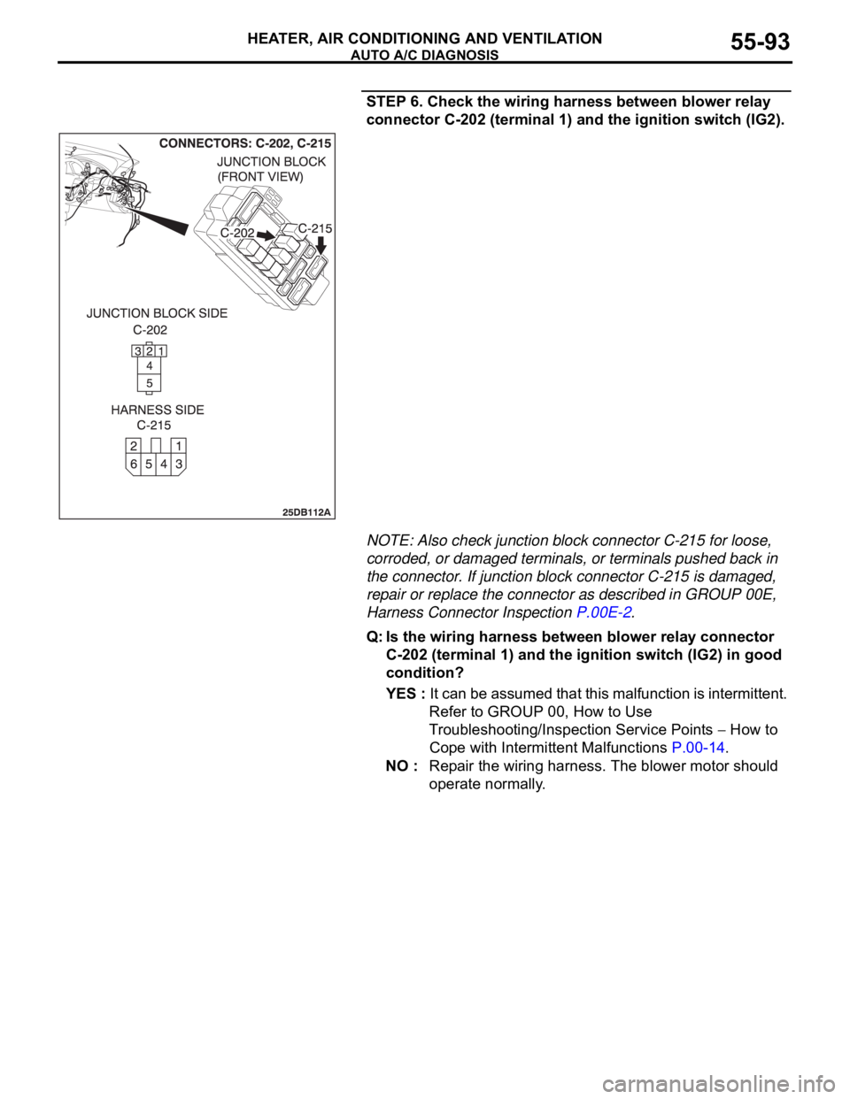
STEP 6. Check the wiring harness between blower relay
connector C-202 (terminal 1) and the ignition switch (IG2).
NOTE: Also check junction block connector C-215 for loose,
corroded, or damaged terminals, or terminals pushed back in
the connector. If junction block connector C-215 is damaged,
repair or replace the connector as described in GROUP 00E,
Harness Connector Inspection P.00E-2.
Q: Is the wiring harness between blower relay connector
C-202 (terminal 1) and the ignition switch (IG2) in good
condition?
YES : It can be assumed that this malfunction is intermittent.
Refer to GROUP 00, How to Use
Troubleshooting/Inspection Service Points
How to
Cope with Intermittent Malfunctions P.00-14.
NO : Repair the wiring harness. The blower motor should
operate normally.
Page 795 of 1500
AUTO A/C DIAGNOSIS
HEATER, AIR CONDITIONING AND VENTILATION55-94
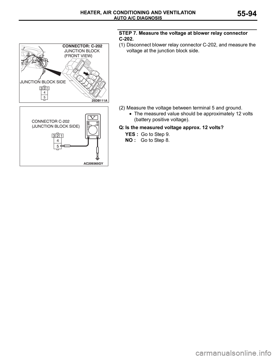
STEP 7. Measure the voltage at blower relay connector
C-202.
(1) Disconnect blower relay connector C-202, and measure the
voltage at the junction block side.
(2) Measure the voltage between terminal 5 and ground.
The measured value should be approximately 12 volts
(battery positive voltage).
Q: Is the measured voltage approx. 12 volts?
YES : Go to Step 9.
NO : Go to Step 8.
Page 796 of 1500
AUTO A/C DIAGNOSIS
HEATER, AIR CONDITIONING AND VENTILATION55-95
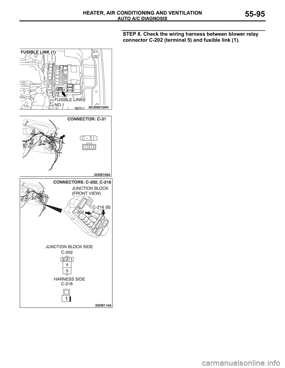
STEP 8. Check the wiring harness between blower relay
connector C-202 (terminal 5) and fusible link (1).
Page 797 of 1500
AUTO A/C DIAGNOSIS
HEATER, AIR CONDITIONING AND VENTILATION55-96
NOTE: Also check intermediate connector C-31 and junction
block connector C-216 for loose, corroded, or damaged termi-
nals, or terminals pushed back in the connector. If intermediate
connector C-31, junction block connector C-216 is damaged,
repair or replace the connector as described in GROUP 00E,
Harness Connector Inspection P.00E-2.
Q: Is the wiring harness between blower relay connector
C-202 (terminal 5) and fusible link (1) in good condition?
YES : It can be assumed that this malfunction is intermittent.
Refer to GROUP 00, How to Use
Troubleshooting/Inspection Service Points
How to
Cope with Intermittent Malfunctions P.00-14.
NO : Repair the wiring harness. The blower motor should
operate normally.
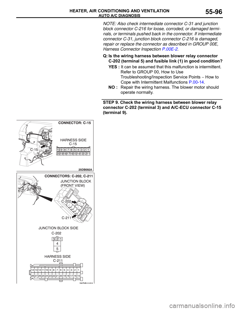
STEP 9. Check the wiring harness between blower relay
connector C-202 (terminal 3) and A/C-ECU connector C-15
(terminal 9).
Page 798 of 1500
AUTO A/C DIAGNOSIS
HEATER, AIR CONDITIONING AND VENTILATION55-97
NOTE: Also check junction block connector C-211 for loose,
corroded, or damaged terminals, or terminals pushed back in
the connector. If junction block connector C-211 is damaged,
repair or replace the connector as described in GROUP 00E,
Harness Connector Inspection P.00E-2.
Q: Is the wiring harness between blower relay connector
C-202 (terminal 3) and A/C-ECU connector C-15
(terminal 9) in good condition?
YES : Go to Step 10.
NO : Repair the wiring harness. The blower motor should
operate normally.
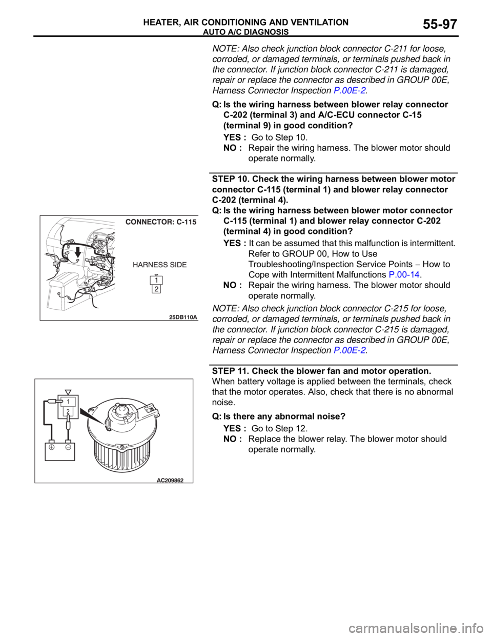
STEP 10. Check the wiring harness between blower motor
connector C-115 (terminal 1) and blower relay connector
C-202 (terminal 4).
Q: Is the wiring harness between blower motor connector
C-115 (terminal 1) and blower relay connector C-202
(terminal 4) in good condition?
YES : It can be assumed that this malfunction is intermittent.
Refer to GROUP 00, How to Use
Troubleshooting/Inspection Service Points
How to
Cope with Intermittent Malfunctions P.00-14.
NO : Repair the wiring harness. The blower motor should
operate normally.
NOTE: Also check junction block connector C-215 for loose,
corroded, or damaged terminals, or terminals pushed back in
the connector. If junction block connector C-215 is damaged,
repair or replace the connector as described in GROUP 00E,
Harness Connector Inspection P.00E-2.
STEP 11. Check the blower fan and motor operation.
When battery voltage is applied between the terminals, check
that the motor operates. Also, check that there is no abnormal
noise.
Q: Is there any abnormal noise?
YES : Go to Step 12.
NO : Replace the blower relay. The blower motor should
operate normally.
Page 811 of 1500
AUTO A/C DIAGNOSIS
HEATER, AIR CONDITIONING AND VENTILATION55-110
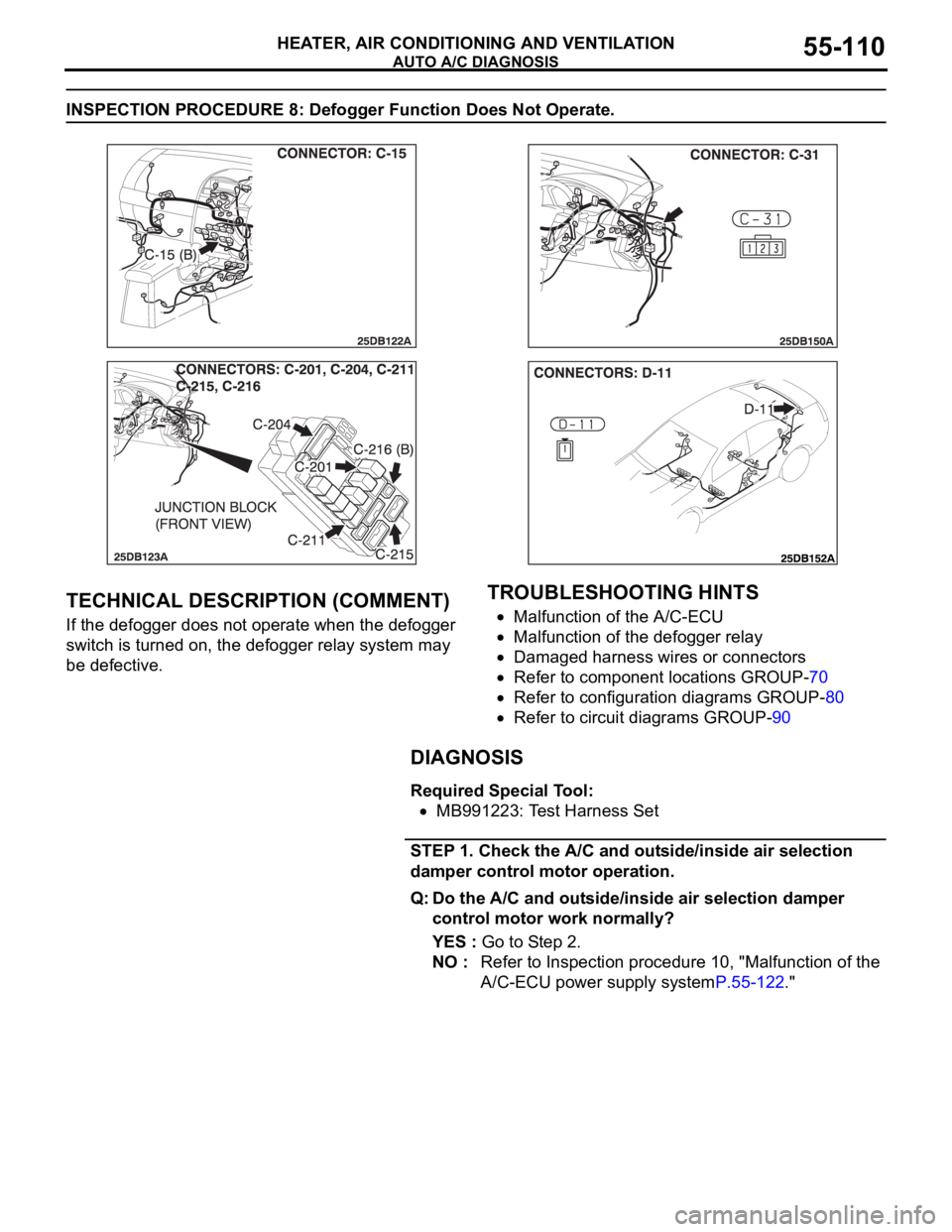
INSPECTION PROCEDURE 8: Defogger Function Does Not Operate.
.
TECHNICAL DESCRIPTION (COMMENT)
If the defogger does not operate when the defogger
switch is turned on, the defogger relay system may
be defective.
.
TROUBLESHOOTING HINTS
Malfunction of the A/C-ECU
Malfunction of the defogger relay
Damaged harness wires or connectors
Refer to component locations GROUP-70
Refer to configuration diagrams GROUP-80
Refer to circuit diagrams GROUP-90
DIAGNOSIS
Required Special Tool:
MB991223: Test Harness Set
STEP 1. Check the A/C and outside/inside air selection
damper control motor operation.
Q: Do the A/C and outside/inside air selection damper
control motor work normally?
YES : Go to Step 2.
NO : Refer to Inspection procedure 10, "Malfunction of the
A/C-ECU power supply systemP.55-122."
Page 812 of 1500
AUTO A/C DIAGNOSIS
HEATER, AIR CONDITIONING AND VENTILATION55-111
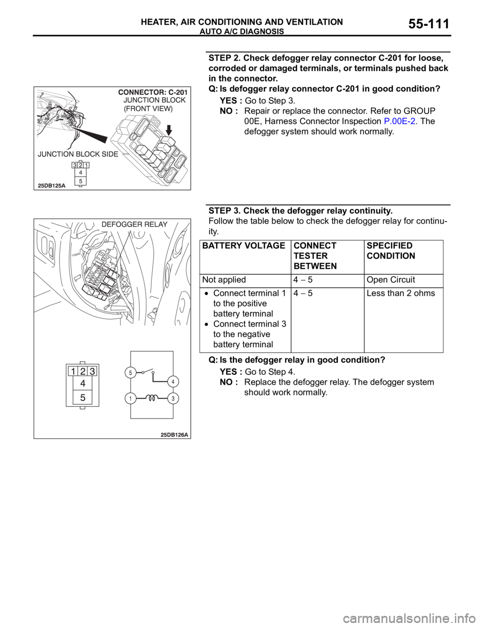
STEP 2. Check defogger relay connector C-201 for loose,
corroded or damaged terminals, or terminals pushed back
in the connector.
Q: Is defogger relay connector C-201 in good condition?
YES : Go to Step 3.
NO : Repair or replace the connector. Refer to GROUP
00E, Harness Connector Inspection P.00E-2. The
defogger system should work normally.
STEP 3. Check the defogger relay continuity.
Follow the table below to check the defogger relay for continu-
ity.
Q: Is the defogger relay in good condition?
YES : Go to Step 4.
NO : Replace the defogger relay. The defogger system
should work normally.
BATTERY VOLTAGE CONNECT
TESTER
BETWEENSPECIFIED
CONDITION
Not applied 4
5 Open Circuit
Connect terminal 1
to the positive
battery terminal
Connect terminal 3
to the negative
battery terminal4
5 Less than 2 ohms
Page 815 of 1500
AUTO A/C DIAGNOSIS
HEATER, AIR CONDITIONING AND VENTILATION55-114
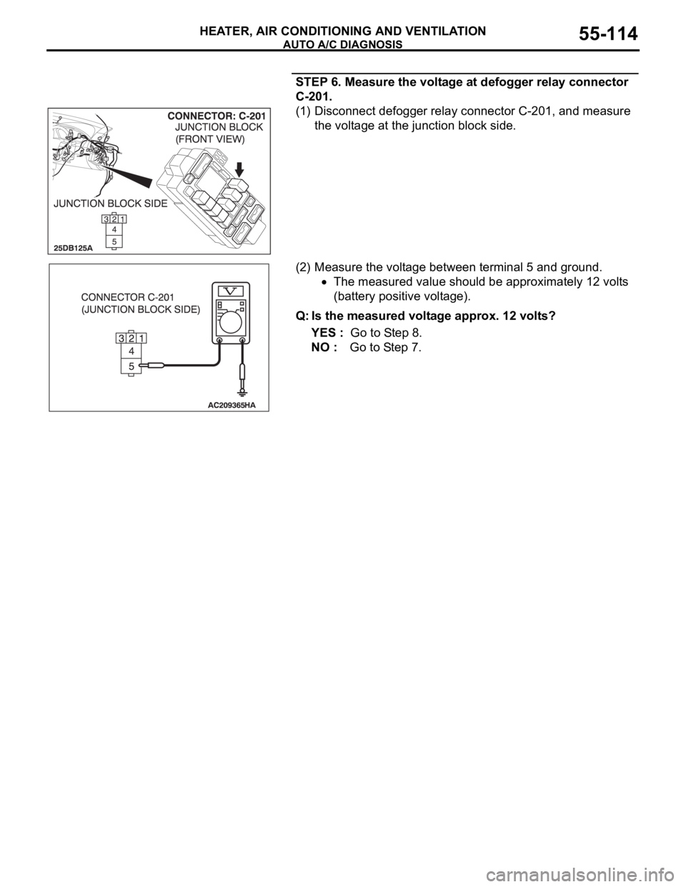
STEP 6. Measure the voltage at defogger relay connector
C-201.
(1) Disconnect defogger relay connector C-201, and measure
the voltage at the junction block side.
(2) Measure the voltage between terminal 5 and ground.
The measured value should be approximately 12 volts
(battery positive voltage).
Q: Is the measured voltage approx. 12 volts?
YES : Go to Step 8.
NO : Go to Step 7.
Page 816 of 1500
AUTO A/C DIAGNOSIS
HEATER, AIR CONDITIONING AND VENTILATION55-115
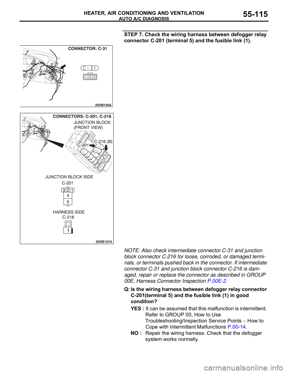
STEP 7. Check the wiring harness between defogger relay
connector C-201 (terminal 5) and the fusible link (1).
NOTE: Also check intermediate connector C-31 and junction
block connector C-216 for loose, corroded, or damaged termi-
nals, or terminals pushed back in the connector. If intermediate
connector C-31 and junction block connector C-216 is dam-
aged, repair or replace the connector as described in GROUP
00E, Harness Connector Inspection P.00E-2.
Q: Is the wiring harness between defogger relay connector
C-201(terminal 5) and the fusible link (1) in good
condition?
YES : It can be assumed that this malfunction is intermittent.
Refer to GROUP 00, How to Use
Troubleshooting/Inspection Service Points
How to
Cope with Intermittent Malfunctions P.00-14.
NO : Repair the wiring harness. Check that the defogger
system works normally.
Page 817 of 1500
AUTO A/C DIAGNOSIS
HEATER, AIR CONDITIONING AND VENTILATION55-116
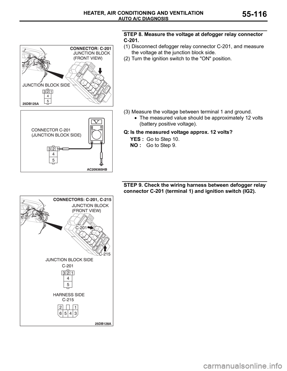
STEP 8. Measure the voltage at defogger relay connector
C-201.
(1) Disconnect defogger relay connector C-201, and measure
the voltage at the junction block side.
(2) Turn the ignition switch to the "ON" position.
(3) Measure the voltage between terminal 1 and ground.
The measured value should be approximately 12 volts
(battery positive voltage).
Q: Is the measured voltage approx. 12 volts?
YES : Go to Step 10.
NO : Go to Step 9.
STEP 9. Check the wiring harness between defogger relay
connector C-201 (terminal 1) and ignition switch (IG2).