relay MITSUBISHI 380 2005 Repair Manual
[x] Cancel search | Manufacturer: MITSUBISHI, Model Year: 2005, Model line: 380, Model: MITSUBISHI 380 2005Pages: 1500, PDF Size: 47.87 MB
Page 349 of 1500
SYMPTOM PROCEDURES
SIMPLIFIED WIRING SYSTEM (SWS)54B-349
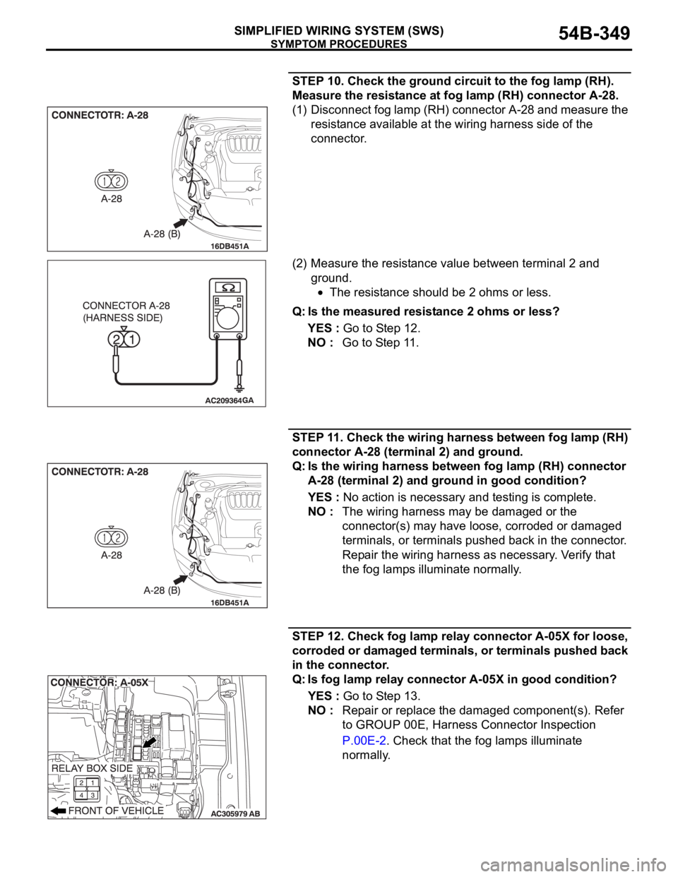
STEP 10. Check the ground circuit to the fog lamp (RH).
Measure the resistance at fog lamp (RH) connector A-28.
(1) Disconnect fog lamp (RH) connector A-28 and measure the
resistance available at the wiring harness side of the
connector.
(2) Measure the resistance value between terminal 2 and
ground.
The resistance should be 2 ohms or less.
Q: Is the measured resistance 2 ohms or less?
YES : Go to Step 12.
NO : Go to Step 11.
STEP 11. Check the wiring harness between fog lamp (RH)
connector A-28 (terminal 2) and ground.
Q: Is the wiring harness between fog lamp (RH) connector
A-28 (terminal 2) and ground in good condition?
YES : No action is necessary and testing is complete.
NO : The wiring harness may be damaged or the
connector(s) may have loose, corroded or damaged
terminals, or terminals pushed back in the connector.
Repair the wiring harness as necessary. Verify that
the fog lamps illuminate normally.
STEP 12. Check fog lamp relay connector A-05X for loose,
corroded or damaged terminals, or terminals pushed back
in the connector.
Q: Is fog lamp relay connector A-05X in good condition?
YES : Go to Step 13.
NO : Repair or replace the damaged component(s). Refer
to GROUP 00E, Harness Connector Inspection
P.00E-2. Check that the fog lamps illuminate
normally.
Page 350 of 1500
SYMPTOM PROCEDURES
SIMPLIFIED WIRING SYSTEM (SWS)54B-350
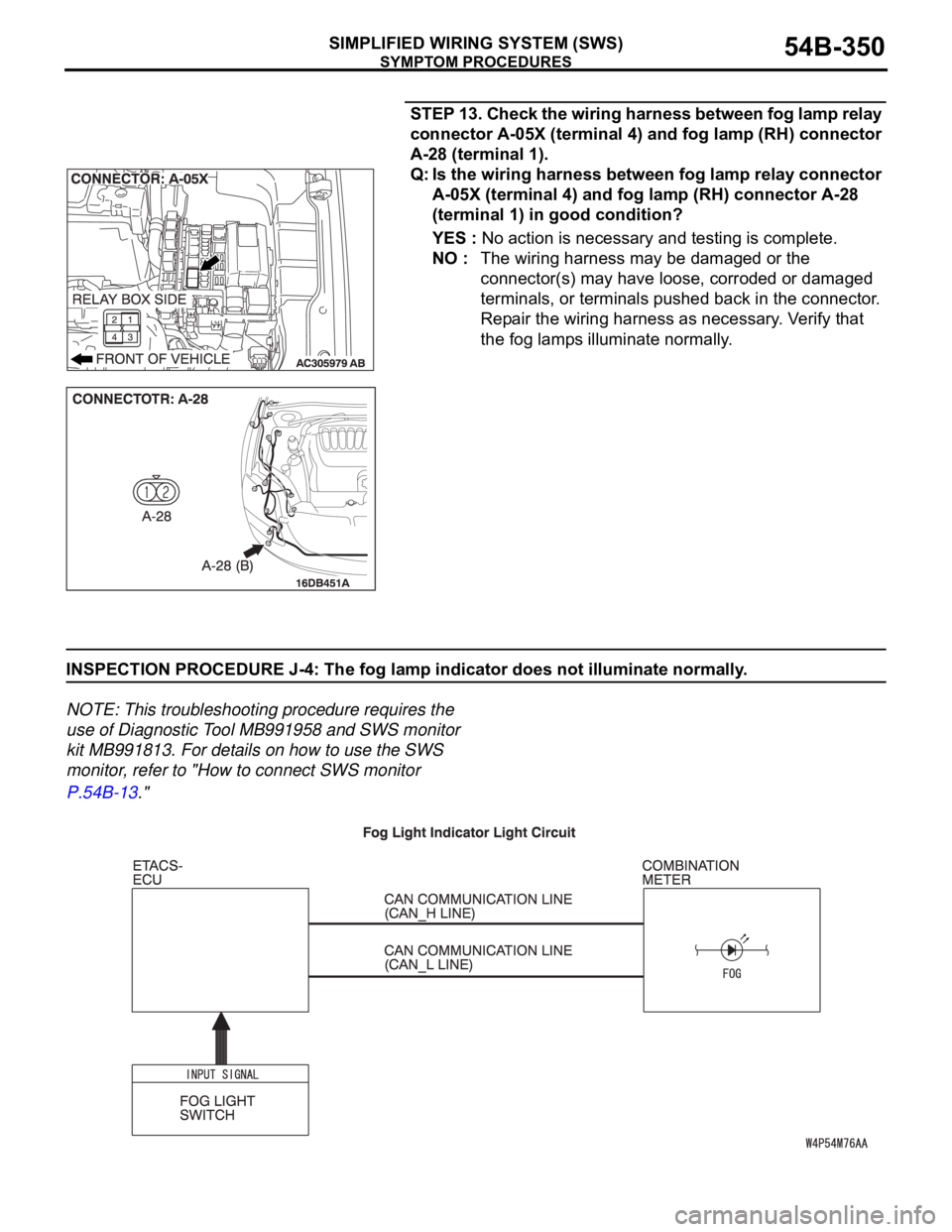
STEP 13. Check the wiring harness between fog lamp relay
connector A-05X (terminal 4) and fog lamp (RH) connector
A-28 (terminal 1).
Q: Is the wiring harness between fog lamp relay connector
A-05X (terminal 4) and fog lamp (RH) connector A-28
(terminal 1) in good condition?
YES : No action is necessary and testing is complete.
NO : The wiring harness may be damaged or the
connector(s) may have loose, corroded or damaged
terminals, or terminals pushed back in the connector.
Repair the wiring harness as necessary. Verify that
the fog lamps illuminate normally.
INSPECTION PROCEDURE J-4: The fog lamp indicator does not illuminate normally.
NOTE: This troubleshooting procedure requires the
use of Diagnostic Tool MB991958 and SWS monitor
kit MB991813. For details on how to use the SWS
monitor, refer to "How to connect SWS monitor
P.54B-13."
.
Page 480 of 1500
CHECK AT ECU TERMINAL
SIMPLIFIED WIRING SYSTEM (SWS)54B-480
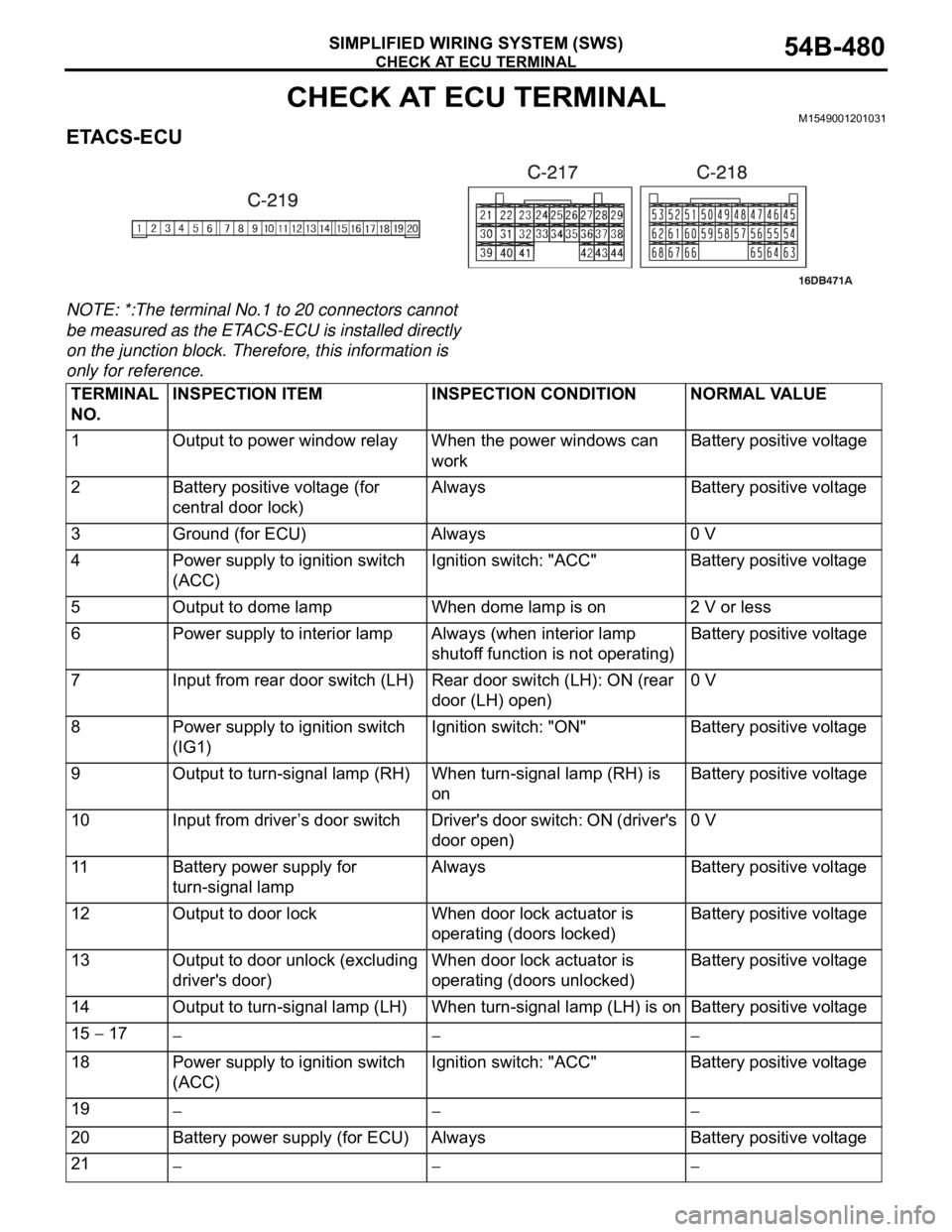
CHECK AT ECU TERMINALM1549001201031
ETACS-ECU
NOTE: *:The terminal No.1 to 20 connectors cannot
be measured as the ETACS-ECU is installed directly
on the junction block. Therefore, this information is
only for reference.
TERMINAL
NO.INSPECTION ITEM INSPECTION CONDITION NORMAL VALUE
1 Output to power window relay When the power windows can
workBattery positive voltage
2 Battery positive voltage (for
central door lock)Always Battery positive voltage
3 Ground (for ECU) Always 0 V
4 Power supply to ignition switch
(ACC)Ignition switch: "ACC" Battery positive voltage
5 Output to dome lamp When dome lamp is on 2 V or less
6 Power supply to interior lamp Always (when interior lamp
shutoff function is not operating)Battery positive voltage
7 Input from rear door switch (LH) Rear door switch (LH): ON (rear
door (LH) open)0 V
8 Power supply to ignition switch
(IG1)Ignition switch: "ON" Battery positive voltage
9 Output to turn-signal lamp (RH) When turn-signal lamp (RH) is
onBattery positive voltage
10 Input from driver’s door switch Driver's door switch: ON (driver's
door open)0 V
11 Battery power supply for
turn-signal lampAlways Battery positive voltage
12 Output to door lock When door lock actuator is
operating (doors locked)Battery positive voltage
13 Output to door unlock (excluding
driver's door)When door lock actuator is
operating (doors unlocked) Battery positive voltage
14 Output to turn-signal lamp (LH) When turn-signal lamp (LH) is on Battery positive voltage
15
17
18 Power supply to ignition switch
(ACC)Ignition switch: "ACC" Battery positive voltage
19
20 Battery power supply (for ECU) Always Battery positive voltage
21
Page 481 of 1500

CHECK AT ECU TERMINAL
SIMPLIFIED WIRING SYSTEM (SWS)54B-481
22 Output to door unlock (for
driver's door)When driver's door lock actuator
is operating (doors unlocked)Battery positive voltage
23, 24
25 Input of door lock key cylinder
switch (UNLOCK) signalDoor lock key cylinder switch:
UNLOCK0 V
26
28
29 Input of rear door lock actuator
(UNLOCK) signalRear door lock actuator:
UNLOCK0 V
30 Input of key reminder switch
signalKey reminder switch: ON (when
ignition key is removed)0 V
31, 32
33 Input of door lock switch (LOCK)
signalDoor lock switch (incorporated in
power window switch): LOCK0 V
34 Input of door lock switch
(UNLOCK) signalDoor lock switch (incorporated in
power window switch): UNLOCK0 V
35 Input from rear door switch (RH) Rear door switch (RH): ON (rear
door (RH) open)0 V
36 Input of driver's door lock
actuator (UNLOCK) signalDriver's door lock actuator:
UNLOCK0 V
37 Input from trunk lid latch
assemblyTrunk lid latch: ON (trunk open) 0 V
38 Ground (for sensor) Always 0 V
39
41
42 Input of door lock key cylinder
switch (LOCK) signalDoor lock key cylinder switch:
LOCK0 V
43 Input of front passenger's door
lock actuator (UNLOCK) signalFront passenger’s door lock
actuator: UNLOCK0 V
44 Output to horn relay When a horn sounds by the
keyless entry horn answerback
function2 V or less
45 Output to data link connector When DTC sets 0
12 V (pulse signal)
When input check signal is
output0
12 V (when input
pulse signal is
fluctuating)
46 Output to trunk lamp When trunk lid latch on. 0 V
47
48 Input of fog lamp switch signal Fog lamp switch: ON 0 V
49 Input of hazard warning lamp
switch signalHazard warning lamp switch: ON
(When the switch is depressed)0 V
50 Ground (for sensor) Always 0 V
51 Key Ring Antenna (+) 0 V 0 V
52 Key Ring Antenna (-) 0 V 0 V
53 SWS communication line Always 0
12 V (pulse signal) TERMINAL
NO.INSPECTION ITEM INSPECTION CONDITION NORMAL VALUE
Page 484 of 1500

CHECK AT ECU TERMINAL
SIMPLIFIED WIRING SYSTEM (SWS)54B-484
FRONT-ECU
NOTE: Terminal voltages cannot be measured as the
front-ECU is installed directly on the relay box.
Therefore, this information is only for reference.
TERMINAL
NO.INSPECTION ITEM INSPECTION CONDITION NORMAL VALUE
1 Output to fog lamp relay When the fog lamps are on Battery positive voltage
2 Output to headlamp (high-beam) When headlights (high-beam)
are onBattery positive voltage
3, 4 Battery power supply (for
headlamp)Always Battery positive voltage
5 Battery power supply (for
taillamp)Always Battery positive voltage
6 Output to headlamp (low-beam) When headlights (low-beam) are
onBattery positive voltage
7 Battery power supply (for ECU) Always Battery positive voltage
8 Output to taillamps When taillamps are on Battery positive voltage
9
11
21 Output to windshield washer When windshield washer is on Battery positive voltage
22 SWS communication line Always 0
12 V (pulse signal)
23 Input of automatic stop signal to
windshield wiperWhen windshield wiper is on Battery positive voltage
24 Power supply to ignition switch
(ACC)Ignition switch: "ACC" Battery positive voltage
25 Input of backup signal from
headlamp switchHeadlamp switch: ON0 V
26 Input of backup signal to
windshield wiperWindshield low-speed wiper
switch or windshield high-speed
wiper switch: ON0 V
27 Output to windshield wiper
(low-speed)When windshield wiper is on (at
low speed)Battery positive voltage
28 Output to windshield wiper
(high-speed)When windshield wiper is on (at
high speed)Battery positive voltage
30 Power supply to ignition switch
(IG2)Ignition switch: "ON" Battery positive voltage
31 Ground Always 0 V
Page 521 of 1500

FRONT SEAT ASSEMBLY
INTERIOR52A-32
CIRCUIT DIAGRAMS:
Refer to circuit diagrams GROUP-90
Refer to configuration diagrams GROUP-80
NOTE: Check connectors and terminals for damage or
loose connections at the seat harness and all supply
circuits connections to seat. Repair or replace wiring
harness if damaged.
ERASING DIAGNOSTIC TROUBLE CODES (DTC’s)
The Memory Seat Controller will temporarily store DTC’s when
incorrect operating conditions are detected. The DTC’s are
self-clearing as soon as each fault condition is rectified and
returns to normal operating function. LED FLASH
SEQUENCEFAULT CONDITION
DETECTEDPOSSIBLE CAUSE
2 then 1 No fore lift motor sensor Connection at motor sensor
or open/ short circuit in
wiring harness.
2 then 2 No aft lift motor sensor Connection at motor sensor
or open/ short circuit in
wiring harness.
2 then 3 No track motor sensor Connection at motor sensor
or open/ short circuit in
wiring harness.
2 then 4 No pedal motor sensor Connection at motor sensor
or open/ short circuit in
wiring harness.
2 then 5 No recliner motor sensor Connection at motor sensor
or open/ short circuit in
wiring harness.
2 then 6 No lumbar motor sensor Connection at motor sensor
or open/ short circuit in
wiring harness.
3 then 1 Button stuck MEMORY Button switch cap stuck on
side cover
3 then 2 Manual Button stuck position Button switch cap stuck on
side cover
6 then 3 Power relay welded shut Grime on contact
Page 553 of 1500
ENGINE COMPARTMENT
CONFIGURATION DIAGRAMS80-4
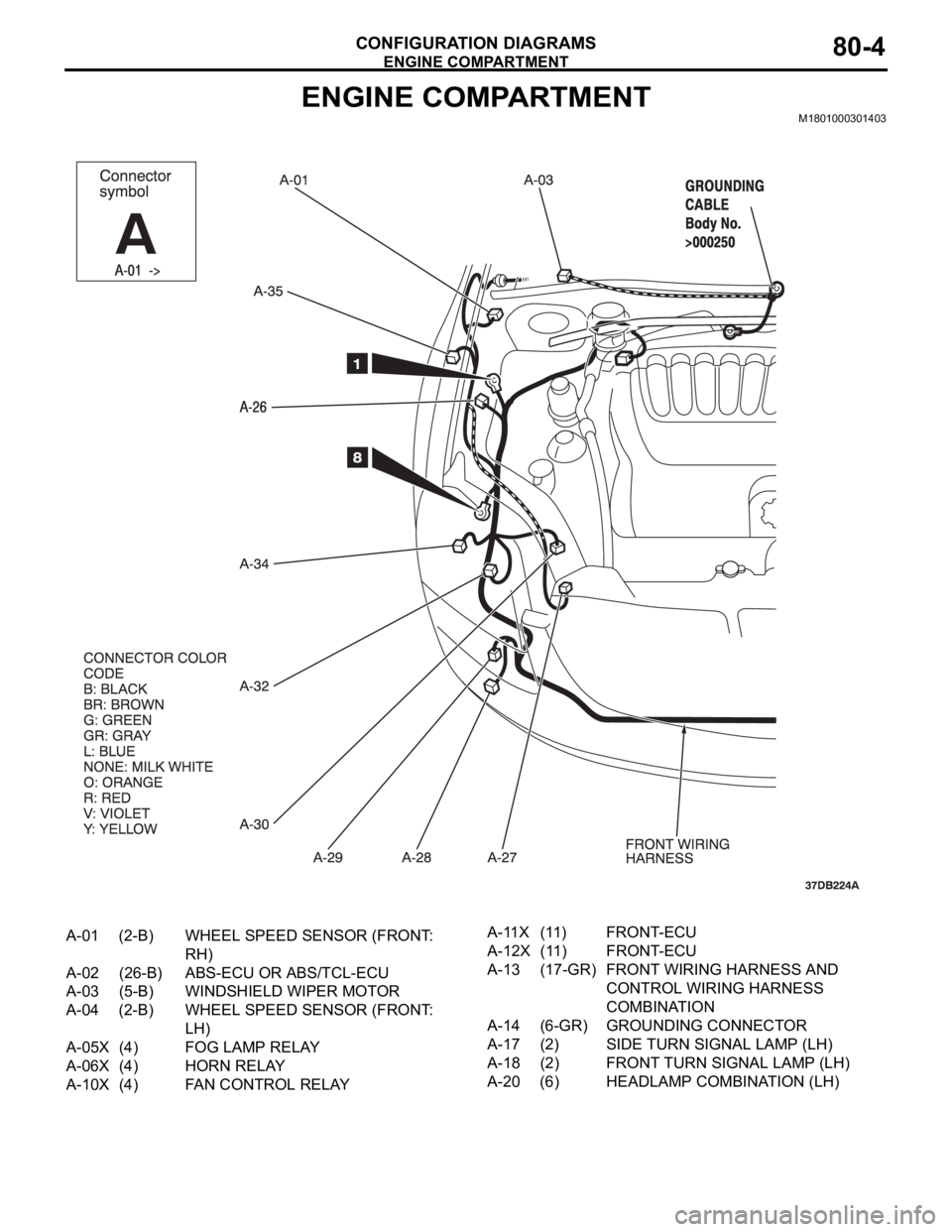
ENGINE COMPARTMENTM1801000301403
A-01 (2-B) WHEEL SPEED SENSOR (FRONT:
RH)
A-02 (26-B) ABS-ECU OR ABS/TCL-ECU
A-03 (5-B) WINDSHIELD WIPER MOTOR
A-04 (2-B) WHEEL SPEED SENSOR (FRONT:
LH)
A-05X (4) FOG LAMP RELAY
A-06X (4) HORN RELAY
A-10X (4) FAN CONTROL RELAYA-11X (11) FRONT-ECU
A-12X (11) FRONT-ECU
A-13 (17-GR) FRONT WIRING HARNESS AND
CONTROL WIRING HARNESS
COMBINATION
A-14 (6-GR) GROUNDING CONNECTOR
A-17 (2) SIDE TURN SIGNAL LAMP (LH)
A-18 (2) FRONT TURN SIGNAL LAMP (LH)
A-20 (6) HEADLAMP COMBINATION (LH)
Page 555 of 1500
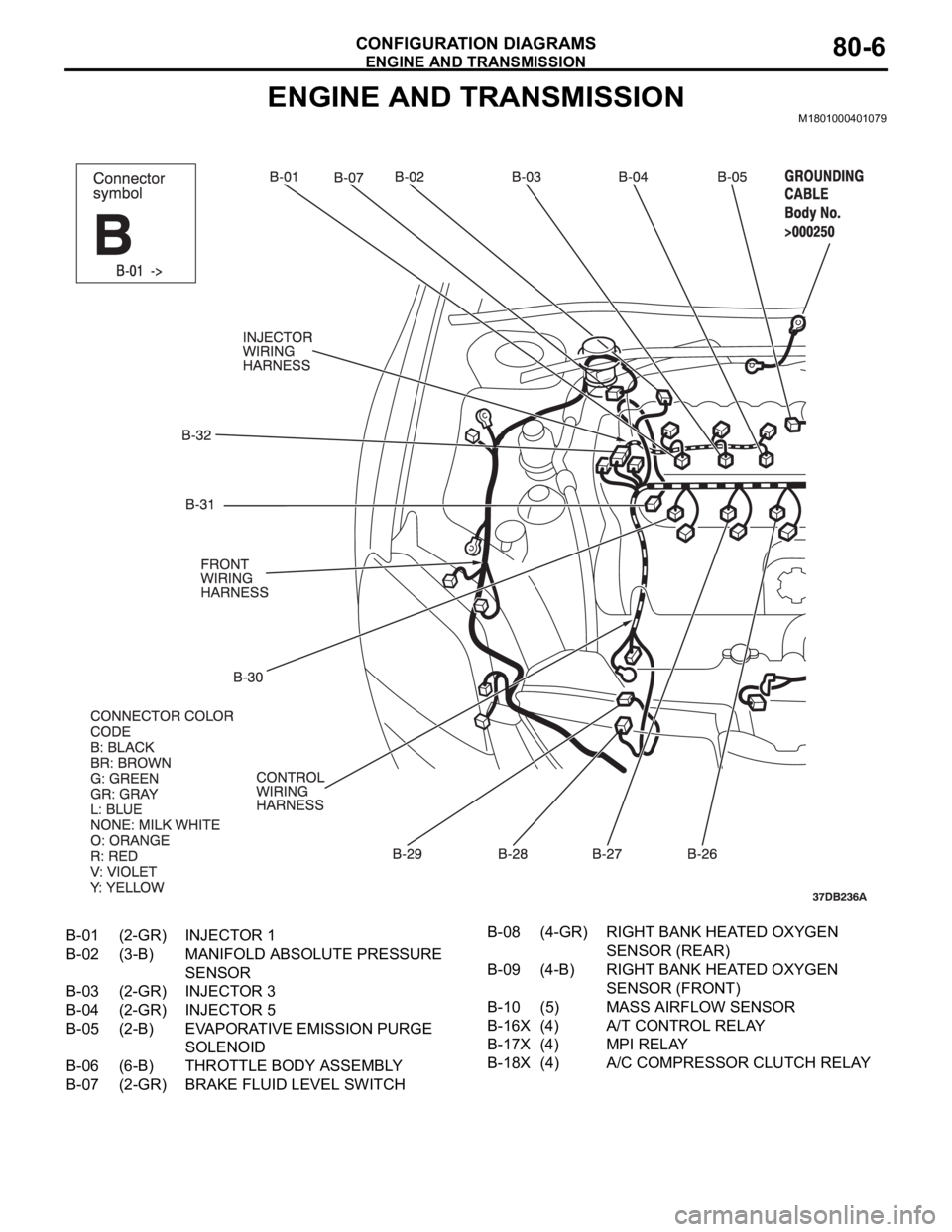
ENGINE AND TRANSMISSION
CONFIGURATION DIAGRAMS80-6
ENGINE AND TRANSMISSIONM1801000401079
B-01 (2-GR) INJECTOR 1
B-02 (3-B) MANIFOLD ABSOLUTE PRESSURE
SENSOR
B-03 (2-GR) INJECTOR 3
B-04 (2-GR) INJECTOR 5
B-05 (2-B) EVAPORATIVE EMISSION PURGE
SOLENOID
B-06 (6-B) THROTTLE BODY ASSEMBLY
B-07 (2-GR) BRAKE FLUID LEVEL SWITCHB-08 (4-GR) RIGHT BANK HEATED OXYGEN
SENSOR (REAR)
B-09 (4-B) RIGHT BANK HEATED OXYGEN
SENSOR (FRONT)
B-10 (5) MASS AIRFLOW SENSOR
B-16X (4) A/T CONTROL RELAY
B-17X (4) MPI RELAY
B-18X (4) A/C COMPRESSOR CLUTCH RELAY
Page 563 of 1500
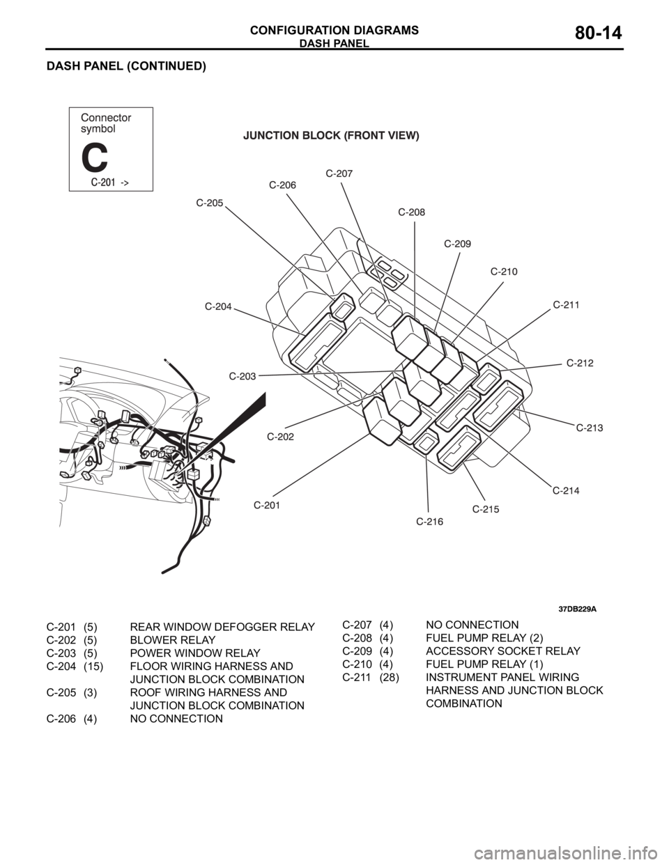
DASH PANEL
CONFIGURATION DIAGRAMS80-14
DASH PANEL (CONTINUED)
C-201 (5) REAR WINDOW DEFOGGER RELAY
C-202 (5) BLOWER RELAY
C-203 (5) POWER WINDOW RELAY
C-204 (15) FLOOR WIRING HARNESS AND
JUNCTION BLOCK COMBINATION
C-205 (3) ROOF WIRING HARNESS AND
JUNCTION BLOCK COMBINATION
C-206 (4) NO CONNECTIONC-207 (4) NO CONNECTION
C-208 (4) FUEL PUMP RELAY (2)
C-209 (4) ACCESSORY SOCKET RELAY
C-210 (4) FUEL PUMP RELAY (1)
C-211 (28) INSTRUMENT PANEL WIRING
HARNESS AND JUNCTION BLOCK
COMBINATION
Page 587 of 1500
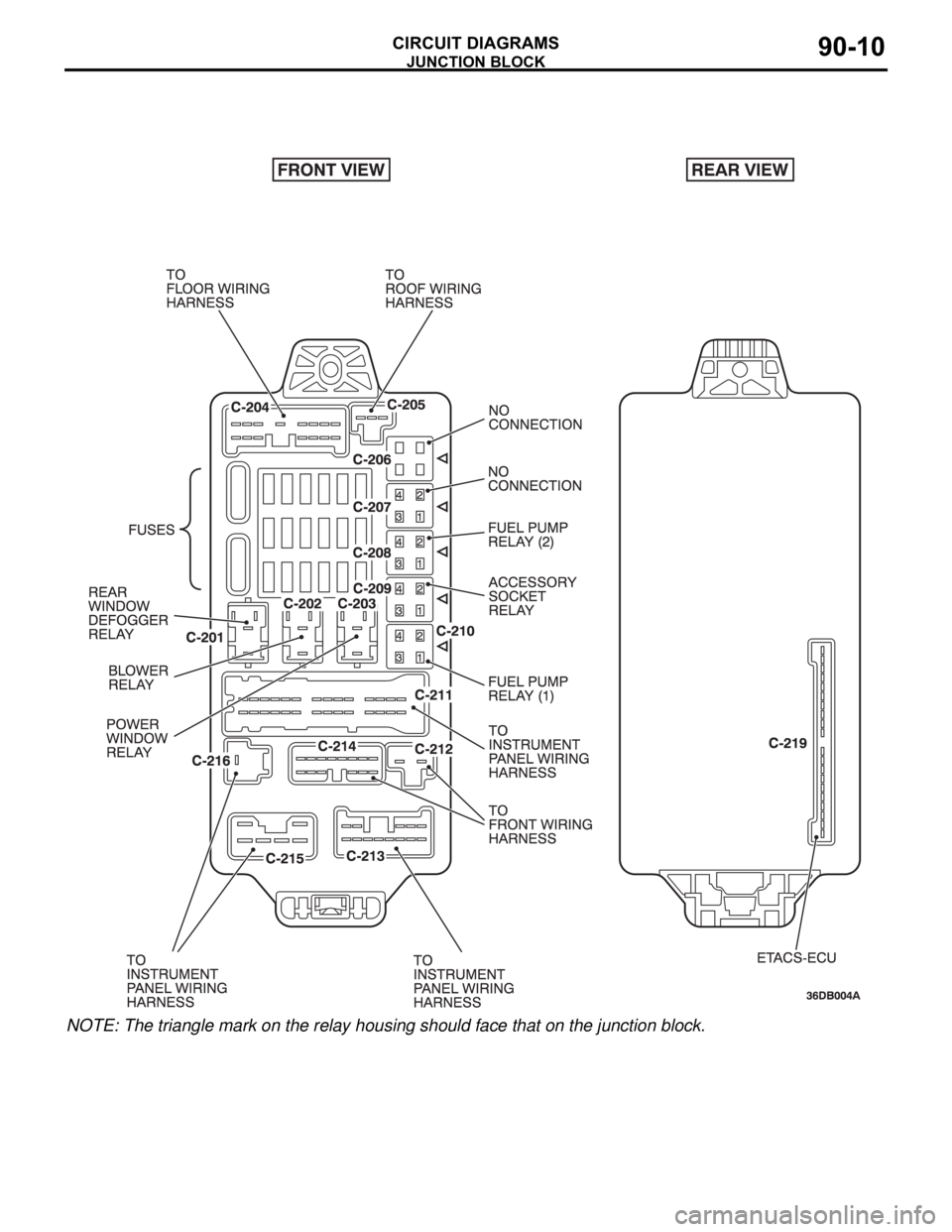
JUNCTION BLOCK
CIRCUIT DIAGRAMS90-10
NOTE: The triangle mark on the relay housing should face that on the junction block.