Dash MITSUBISHI 380 2005 Workshop Manual
[x] Cancel search | Manufacturer: MITSUBISHI, Model Year: 2005, Model line: 380, Model: MITSUBISHI 380 2005Pages: 1500, PDF Size: 47.87 MB
Page 550 of 1500

80-1
GROUP 80
CONFIGURATION
DIAGRAMS
CONTENTS
OVERALL CONFIGURATION
DIAGRAM. . . . . . . . . . . . . . . . . . . . . .80-2
HOW TO READ CONFIGURATION
DIAGRAMS . . . . . . . . . . . . . . . . . . . .80-3
ENGINE COMPARTMENT. . . . . . . . .80-4ENGINE AND TRANSMISSION . . . . .80-6
DASH PANEL . . . . . . . . . . . . . . . . . . .80-10
FLOOR, SEAT AND ROOF . . . . . . . .80-17
DOOR . . . . . . . . . . . . . . . . . . . . . . . . .80-23
LUGGAGE COMPARTMENT . . . . . . .80-24
Page 559 of 1500
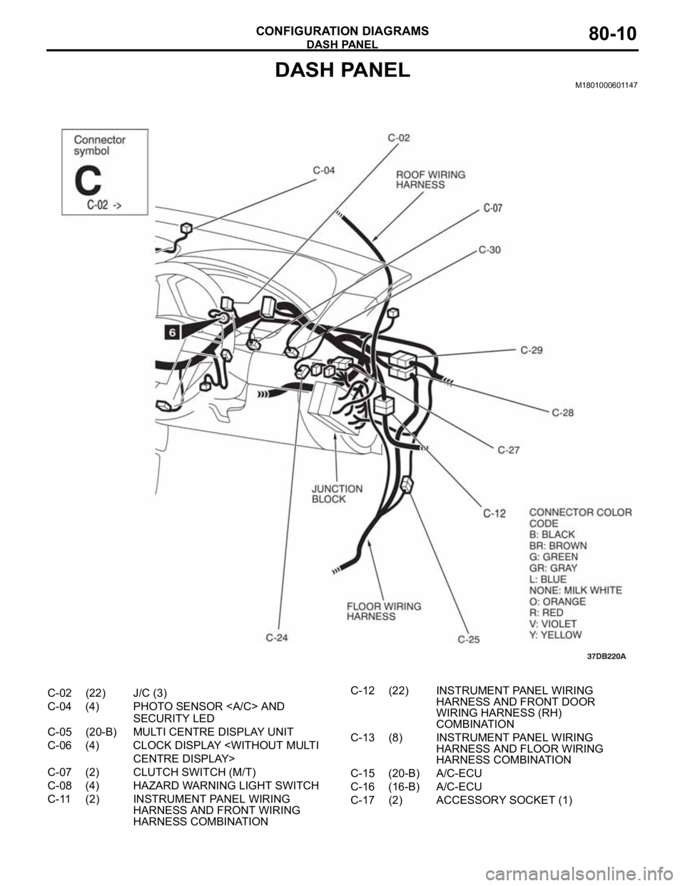
DASH PANEL
CONFIGURATION DIAGRAMS80-10
DASH PANELM1801000601147
C-02 (22) J/C (3)
C-04 (4) PHOTO SENSOR AND
SECURITY LED
C-05 (20-B) MULTI CENTRE DISPLAY UNIT
C-06 (4) CLOCK DISPLAY
C-07 (2) CLUTCH SWITCH (M/T)
C-08 (4) HAZARD WARNING LIGHT SWITCH
C-11 (2) INSTRUMENT PANEL WIRING
HARNESS AND FRONT WIRING
HARNESS COMBINATIONC-12 (22) INSTRUMENT PANEL WIRING
HARNESS AND FRONT DOOR
WIRING HARNESS (RH)
COMBINATION
C-13 (8) INSTRUMENT PANEL WIRING
HARNESS AND FLOOR WIRING
HARNESS COMBINATION
C-15 (20-B) A/C-ECU
C-16 (16-B) A/C-ECU
C-17 (2) ACCESSORY SOCKET (1)
Page 560 of 1500
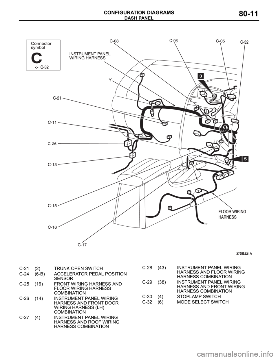
DASH PANEL
CONFIGURATION DIAGRAMS80-11
C-21 (2) TRUNK OPEN SWITCH
C-24 (6-B) ACCELERATOR PEDAL POSITION
SENSOR
C-25 (16) FRONT WIRING HARNESS AND
FLOOR WIRING HARNESS
COMBINATION
C-26 (14) INSTRUMENT PANEL WIRING
HARNESS AND FRONT DOOR
WIRING HARNESS (LH)
COMBINATION
C-27 (4) INSTRUMENT PANEL WIRING
HARNESS AND ROOF WIRING
HARNESS COMBINATIONC-28 (43) INSTRUMENT PANEL WIRING
HARNESS AND FLOOR WIRING
HARNESS COMBINATION
C-29 (38) INSTRUMENT PANEL WIRING
HARNESS AND FRONT WIRING
HARNESS COMBINATION
C-30 (4) STOPLAMP SWITCH
C-32 (6) MODE SELECT SWITCH
Page 561 of 1500
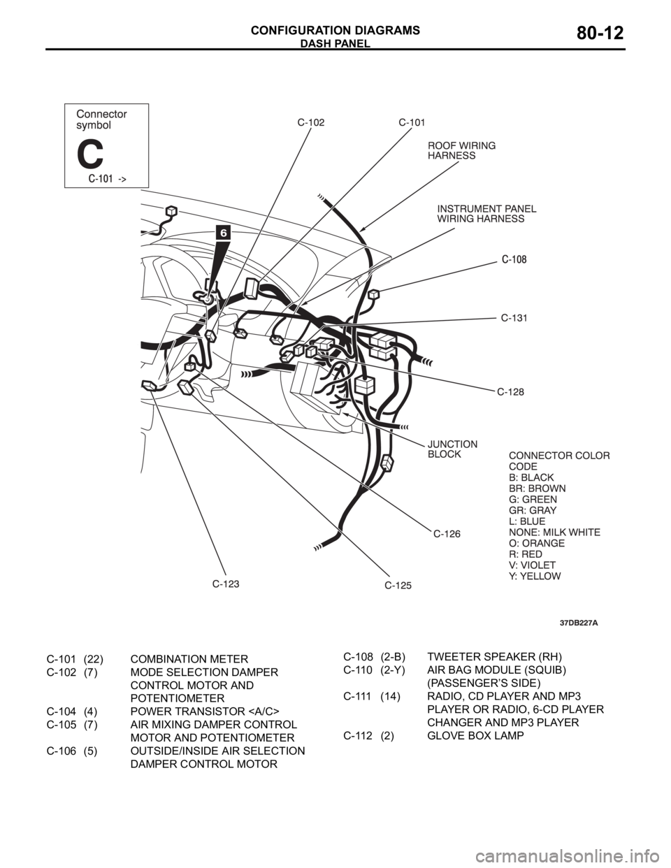
DASH PANEL
CONFIGURATION DIAGRAMS80-12
C-101 (22) COMBINATION METER
C-102 (7) MODE SELECTION DAMPER
CONTROL MOTOR AND
POTENTIOMETER
C-104 (4) POWER TRANSISTOR
C-105 (7) AIR MIXING DAMPER CONTROL
MOTOR AND POTENTIOMETER
C-106 (5) OUTSIDE/INSIDE AIR SELECTION
DAMPER CONTROL MOTORC-108 (2-B) TWEETER SPEAKER (RH)
C-110 (2-Y) AIR BAG MODULE (SQUIB)
(PASSENGER’S SIDE)
C-111 (14) RADIO, CD PLAYER AND MP3
PLAYER OR RADIO, 6-CD PLAYER
CHANGER AND MP3 PLAYER
C-112 (2) GLOVE BOX LAMP
Page 562 of 1500
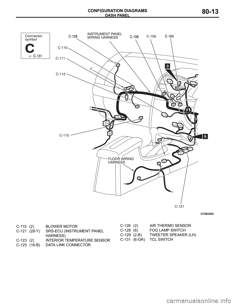
DASH PANEL
CONFIGURATION DIAGRAMS80-13
C-115 (2) BLOWER MOTOR
C-121 (28-Y) SRS-ECU (INSTRUMENT PANEL
HARNESS)
C-123 (2) INTERIOR TEMPERATURE SENSOR
C-125 (16-B) DATA LINK CONNECTORC-126 (2) AIR THERMO SENSOR
C-128 (6) FOG LAMP SWITCH
C-129 (2-B) TWEETER SPEAKER (LH)
C-131 (6-GR) TCL SWITCH
Page 563 of 1500
DASH PANEL
CONFIGURATION DIAGRAMS80-14
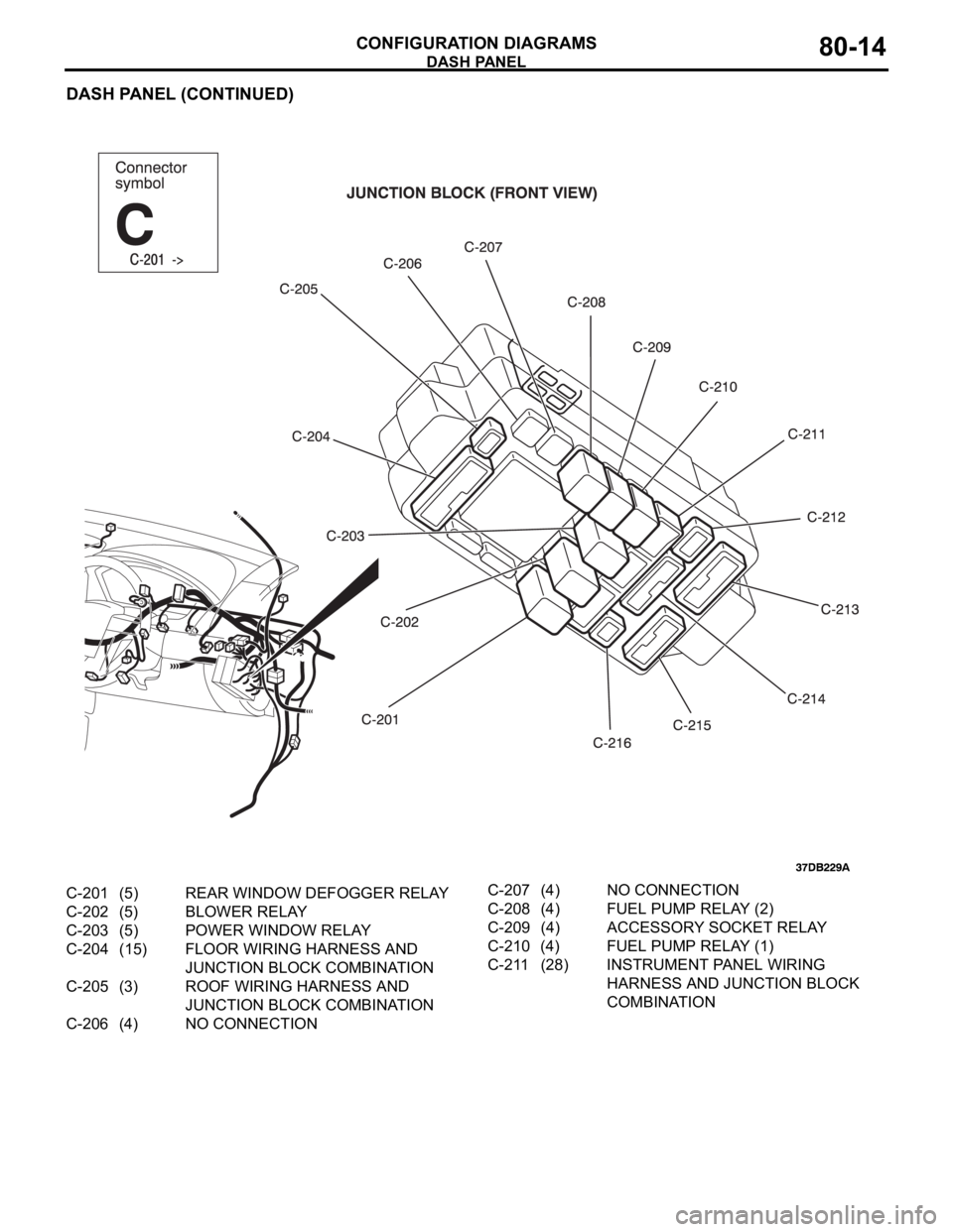
DASH PANEL (CONTINUED)
C-201 (5) REAR WINDOW DEFOGGER RELAY
C-202 (5) BLOWER RELAY
C-203 (5) POWER WINDOW RELAY
C-204 (15) FLOOR WIRING HARNESS AND
JUNCTION BLOCK COMBINATION
C-205 (3) ROOF WIRING HARNESS AND
JUNCTION BLOCK COMBINATION
C-206 (4) NO CONNECTIONC-207 (4) NO CONNECTION
C-208 (4) FUEL PUMP RELAY (2)
C-209 (4) ACCESSORY SOCKET RELAY
C-210 (4) FUEL PUMP RELAY (1)
C-211 (28) INSTRUMENT PANEL WIRING
HARNESS AND JUNCTION BLOCK
COMBINATION
Page 564 of 1500
DASH PANEL
CONFIGURATION DIAGRAMS80-15
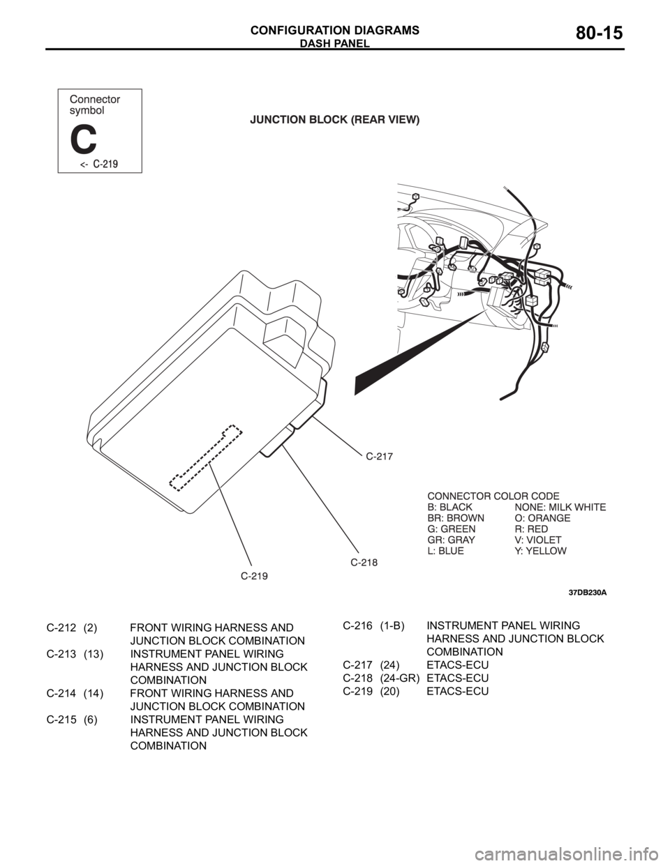
C-212 (2) FRONT WIRING HARNESS AND
JUNCTION BLOCK COMBINATION
C-213 (13) INSTRUMENT PANEL WIRING
HARNESS AND JUNCTION BLOCK
COMBINATION
C-214 (14) FRONT WIRING HARNESS AND
JUNCTION BLOCK COMBINATION
C-215 (6) INSTRUMENT PANEL WIRING
HARNESS AND JUNCTION BLOCK
COMBINATIONC-216 (1-B) INSTRUMENT PANEL WIRING
HARNESS AND JUNCTION BLOCK
COMBINATION
C-217 (24) ETACS-ECU
C-218 (24-GR) ETACS-ECU
C-219 (20) ETACS-ECU
Page 565 of 1500
DASH PANEL
CONFIGURATION DIAGRAMS80-16
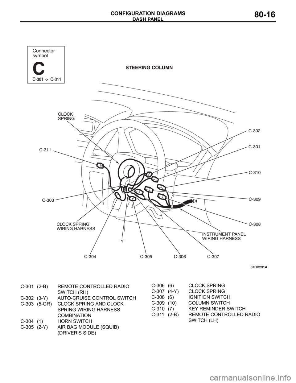
C-301 (2-B) REMOTE CONTROLLED RADIO
SWITCH (RH)
C-302 (3-Y) AUTO-CRUISE CONTROL SWITCH
C-303 (5-GR) CLOCK SPRING AND CLOCK
SPRING WIRING HARNESS
COMBINATION
C-304 (1) HORN SWITCH
C-305 (2-Y) AIR BAG MODULE (SQUIB)
(DRIVER’S SIDE)C-306 (6) CLOCK SPRING
C-307 (4-Y) CLOCK SPRING
C-308 (6) IGNITION SWITCH
C-309 (10) COLUMN SWITCH
C-310 (7) KEY REMINDER SWITCH
C-311 (2-B) REMOTE CONTROLLED RADIO
SWITCH (LH)
Page 1178 of 1500
ON-VEHICLE SERVICE
BASIC BRAKE SYSTEM35A-13
ON-VEHICLE SERVICE
BRAKE PEDAL CHECK AND ADJUSTMENTM1351000900446
BRAKE PEDAL HEIGHT
1. Turn up the carpet, etc. under the brake pedal.
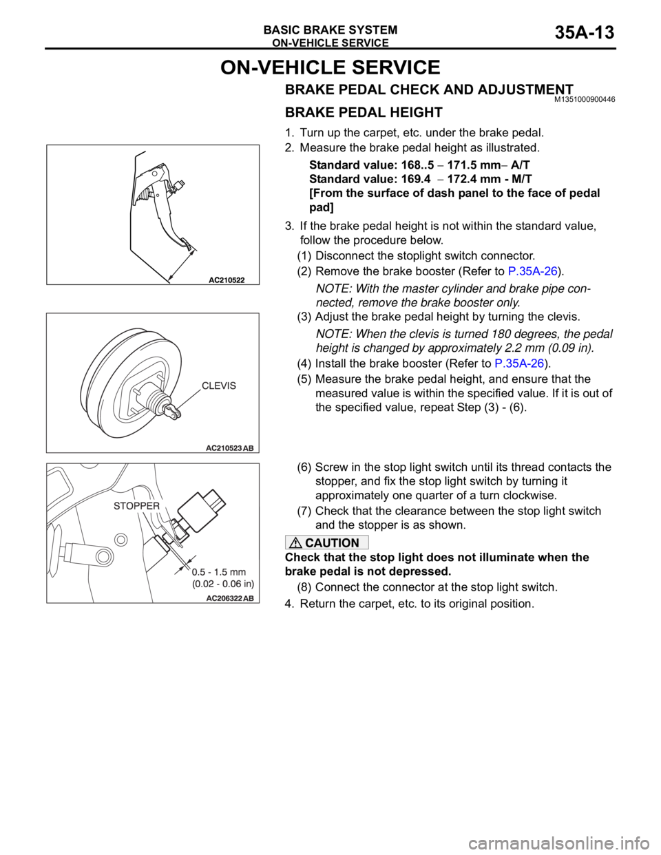
2. Measure the brake pedal height as illustrated.
Standard value: 168..5
171.5 mm A/T
Standard value: 169.4
172.4 mm - M/T
[From the surface of dash panel to the face of pedal
pad]
3. If the brake pedal height is not within the standard value,
follow the procedure below.
(1) Disconnect the stoplight switch connector.
(2) Remove the brake booster (Refer to P.35A-26).
NOTE: With the master cylinder and brake pipe con-
nected, remove the brake booster only.
(3) Adjust the brake pedal height by turning the clevis.
NOTE: When the clevis is turned 180 degrees, the pedal
height is changed by approximately 2.2 mm (0.09 in).
(4) Install the brake booster (Refer to P.35A-26).
(5) Measure the brake pedal height, and ensure that the
measured value is within the specified value. If it is out of
the specified value, repeat Step (3) - (6).
(6) Screw in the stop light switch until its thread contacts the
stopper, and fix the stop light switch by turning it
approximately one quarter of a turn clockwise.
(7) Check that the clearance between the stop light switch
and the stopper is as shown.
Check that the stop light does not illuminate when the
brake pedal is not depressed.
(8) Connect the connector at the stop light switch.
4. Return the carpet, etc. to its original position.
Page 1179 of 1500
ON-VEHICLE SERVICE
BASIC BRAKE SYSTEM35A-14
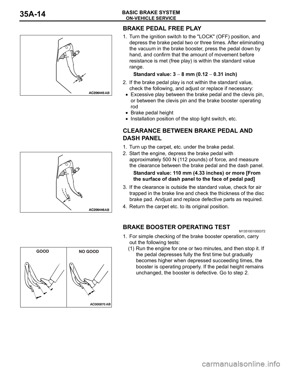
BRAKE PEDAL FREE PLAY
1. Turn the ignition switch to the "LOCK" (OFF) position, and
depress the brake pedal two or three times. After eliminating
the vacuum in the brake booster, press the pedal down by
hand, and confirm that the amount of movement before
resistance is met (free play) is within the standard value
range.
Standard value: 3
8 mm (0.12 0.31 inch)
2. If the brake pedal play is not within the standard value,
check the following, and adjust or replace if necessary:
Excessive play between the brake pedal and the clevis pin,
or between the clevis pin and the brake booster operating
rod
Brake pedal height
Installation position of the stop light switch, etc.
CLEARANCE BETWEEN BRAKE PEDAL AND
DASH PANEL
1. Turn up the carpet, etc. under the brake pedal.
2. Start the engine, depress the brake pedal with
approximately 500 N (112 pounds) of force, and measure
the clearance between the brake pedal and the dash panel.
Standard value: 110 mm (4.33 inches) or more [From
the surface of dash panel to the face of pedal pad]
3. If the clearance is outside the standard value, check for air
trapped in the brake line and check the thickness of the disc
brake pad. Andjust and replace defective parts as required.
4. Return the carpet etc. to its original position.
BRAKE BOOSTER OPERATING TESTM1351001000372
1. For simple checking of the brake booster operation, carry
out the following tests:
(1) Run the engine for one or two minutes, and then stop it. If
the pedal depresses fully the first time but gradually
becomes higher when depressed succeeding times, the
booster is operating properly. If the pedal height remains
unchanged, the booster is defective. Go to step 2.