display MITSUBISHI 380 2005 Workshop Manual
[x] Cancel search | Manufacturer: MITSUBISHI, Model Year: 2005, Model line: 380, Model: MITSUBISHI 380 2005Pages: 1500, PDF Size: 47.87 MB
Page 2 of 1500

GENERAL DESCRIPTION
SIMPLIFIED WIRING SYSTEM (SWS)54B-2
GENERAL DESCRIPTION
COMMUNICATION METHODM1549013000547
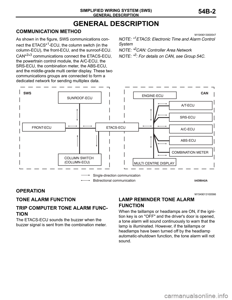
As shown in the figure, SWS communications con-
nect the ETACS*
1-ECU, the column switch (in the
column-ECU), the front-ECU, and the sunroof-ECU.
CAN*
2*3 communications connect the ETACS-ECU,
the powertrain control module, the A/C-ECU, the
SRS-ECU, the combination meter, the ABS-ECU,
and the middle-grade multi center display. These two
communications groups are connected to form a
dedicated network for sending multiplex data.NOTE: *
1ETACS: Electronic Time and Alarm Control
System
NOTE: *
2CAN: Controller Area Network
NOTE: *
3: For details on CAN, see Group 54C.
OPERATIONM1549013100566
TONE ALARM FUNCTION
.
TRIP COMPUTER TONE ALARM FUNC-
TION
The ETACS-ECU sounds the buzzer when the
buzzer signal is sent from the combination meter.
.
LAMP REMINDER TONE ALARM
FUNCTION
When the taillamps or headlamps are ON, if the igni-
tion key is on "OFF" and the driver's door is opened,
a tone alarm will sound continuously to warn that the
lamp is illuminated. However, if the taillamps or
headlamps have been turned off by the headlamp
automatic-shutdown function, the tone alarm will not
sound.
.
Page 3 of 1500

GENERAL DESCRIPTION
SIMPLIFIED WIRING SYSTEM (SWS)54B-3
SEAT BELT TONE ALARM FUNCTION
If any of the following conditions is met with the igni-
tion switch at "ON" or "ST", the ETACS-ECU sounds
the tone alarm by using the driver's seat belt switch
signal and the vehicle speed signal sent from the
combination meter.
Sounds the tone alarm for six seconds when the
ignition switch is turned "ON" with the seat belt
switch on (the driver's seat belt is not fastened).
This is called "Timer function".
Sounds the tone alarm 12 cycles (after 0.5 sec-
onds) if any of the following conditions is met
when sixty seconds or more have elapsed since
the ignition switch is turned "ON". One cycle con-
sists of five-seconds "on" and then three-seconds
"off".
a. The vehicle speed has reached 8 km/h (5
mph) while the seat belt switch is turned on
(driver's seat belt is not fastened) with the
ignition switch "ON.
b. The seat belt switch has been turned on
(driver's seat belt has not been fastened) for
at least ten seconds while the ignition switch
has been turned "ON" and the vehicle speed
has been 8 km/h or more.
NOTE: Once the tone alarm has sounded 12
cycles, it does not sound again until the vehi-
cle speed reduces to 3 km/h (2 mph) or less
even if any of the following conditions is met.
The tone alarm stops sounding if the ignition
switch or the seat belt switch is turned off (the
driver's seat belt is fastened) while the timer
operation is active.
.
DOOR AJAR WARNING BUZZER
The buzzer is sounded 4 times by the ETACS-ECU
to warn the driver if any door is open when the igni-
tion is switched ON and the vehicle speed reaches 8
km/h or faster. The buzzer will continue to sound for
4 times even if the ignition, door status, or vehicle
speed requirements are not maintained.
.
MULTI CENTER DISPLAY OPERATION
TONE
The ETACS-ECU sounds the buzzer when the
buzzer signal is sent from the multi center display.
.
TURN-SIGNAL LAMP BUZZER
The ETACS-ECU sounds the buzzer in sync with the
turn-signal lamps or hazard warning lamps.
CENTRAL DOOR LOCKING SYSTEM
.
CENTRAL DOOR LOCKING SYSTEM
OPERATION
Door unlocking by operating the driver’s door lock
key cylinder:
When the ignition key is inserted in the driver’s
door lock key cylinder and turned clockwise to
unlock the driver’s door, the ETACS-ECU oper-
ates its door unlock relay and passes a current
through the door lock actuator of the driver’s door
for 0.25 seconds to unlock only the driver’s door.
When the ignition key is turned clockwise again,
the ETACS-ECU operates its door unlock relay
and passes a current through the door lock actu-
ators of all doors for 0.25 seconds and to unlock
all doors.
Door locking or unlocking by operating the driver’s or
front passenger’s door lock switch:
When the door is locked by the driver’s or front
passenger’s door lock switch, the ETACS-ECU
operates its door lock relay and passes a current
through the door lock actuators of all doors for
0.25 seconds to lock all doors.
When the door is unlocked by the driver’s or front
passenger's door lock switch, the ETACS-ECU
operates its door unlock relay and passes a cur-
rent through the door lock actuators of all doors
for 0.25 seconds to unlock all doors.
When the door is locked and unlocked by driver’s
or front passenger's door lock switch consecu-
tively, the ETACS-ECU operates its door lock
relay and passes a current through the door lock
actuators of all doors for 0.25 seconds to lock all
doors. Then, the ETACS-ECU operates its door
unlock relay and passes a current through the
door lock actuators of all doors for 0.25 seconds
to unlock all doors. Due to this, there may be a
time lag between the driver’s or front passenger's
door lock switch actuation and the time when all
doors are unlocked.
Page 7 of 1500

GENERAL DESCRIPTION
SIMPLIFIED WIRING SYSTEM (SWS)54B-7
SEAT BELT INDICATOR
If any of the following conditions is met with the igni-
tion switch at "ON" or "ST", the ETACS-ECU illumi-
nates, flashes or extinguishes the seat belt indicator
by using the driver's seat belt switch signal and the
vehicle speed signal sent from the combination
meter.
Illuminates when the ignition switch is at "ON"
and the seat belt switch is turned on (the driver's
seat belt is unfastened).
Flashes and illuminates the indicator 12 cycles
(after 0.5 seconds) if any of the following condi-
tions is met when sixty seconds or more have
elapsed since the ignition switch is turned "ON".
One cycle consists of five-second "flashing" and
then three-second "illumination".
a. The vehicle speed has reached 8 km/h (5
mph) while the seat belt switch is turned on
(driver's seat belt is not fastened) with the
ignition switch "ON.
b. The seat belt switch has been turned on
(driver's seat belt has not been fastened) for
at least ten seconds while the ignition switch
has been turned "ON" and the vehicle speed
has been 8 km/h (5 mph) or more.
NOTE: Once this timer operation has been acti-
vated, it will not be activated again until the
vehicle speed reduces to 3 km/h (2 mph) or
less even if any of the following conditions is
met.
The indicator stops illuminating if the ignition
switch or the seat belt switch is turned off (the
driver's seat belt is fastened) while the timer
operation is active.
DOOR-AJAR INDICATOR LAMP
The combination meter receives the signal sent from
the ETACS-ECU about whether each door or trunk is
open or closed and turns the door ajar indicator lamp
on and off. While the door ajar indicator is illumi-
nated, the door ajar warning function is activated and
the door ajar indicator lamp flashes 4 times. If the
door remains open even after the 4 warning flashes,
the door ajar indicator lamp will be illuminated again.
CONFIGURATION FUNCTION
The following functions can be adjusted by operating
the middle-grade multi center display (if equipped).
Keyless entry horn answerback function
Keyless entry hazard lamp answerback function
Timed locking mechanism
Turn-signal lamp buzzer
Door ajar warning buzzer
Adjustment of door unlocking operation on key-
less entry system
Vehicle speed-dependent wiper function
Headlamp automatic shutdown function
Delay-off time of the dome lamp
Interior lamp automatic shutoff function
Initialisation of above mentioned functions
Page 10 of 1500

SWS DIAGNOSIS
SIMPLIFIED WIRING SYSTEM (SWS)54B-10
SWS DIAGNOSIS
GENERAL DESCRIPTION
BEFORE CARRYING OUT TROUBLESHOOTINGM1549014700710
Before carrying out troubleshooting, check the fol-
lowing two items.
Make sure that the ETACS-ECU, the junction
block (J/B), the front-ECU and the engine com-
partment relay box are connected securely.
Make sure that fuses and fusible links related to
relevant systems are not blown.
Refer to circuit diagrams GROUP-90
Refer to configuration diagrams GROUP-80
DIAGNOSTIC FUNCTIONM1549028900245
ON-BOARD DIAGNOSTICS
If an error occurs in the ECU or the SWS or CAN
communication line which performs the SWS or CAN
communication, the DTC is memorized in
ETACS-ECU. The DTCs have 11 items. The DTCs
are checked to connect diagnostic tool MB991958
(MUT-III sub assembly). The memorised DTCs are
not erased even if the ignition switch is turned to the
LOCK (OFF) position. The DTCs are erased to oper-
ate diagnostic tool MB991958 (MUT-III sub assem-
bly).NOTE:
*1: For vehicles that do not have a sunroof,
the diagnosis code is always sent but it does not indi-
cate a problem.
NOTE:
*2: The diagnosis code for the current prob-
lem is not sent.
NOTE:
*3: For vehicles that do not have a multi cen-
ter display (middle grade type), the diagnosis code is
always sent but it does not indicate a problem.
HOW TO CONNECT THE DIAGNOSTIC TOOL
(MUT-III)
Required Special Tools:
MB991958: DIAGNOSTIC TOOL (MUT-III Sub Assembly)
MB991824: Vehicle Communication Interface (V.C.I.)
MB991827: MUT-III USB Cable
MB991910: MUT-III Main Harness A DTC CODE TROUBLE CONTENT
001 or U1700 Malfunction of SWS communication line or ETACS-ECU
002 or U1701 Malfunction of column switch
003 or U1702 Malfunction of front-ECU
004
*1 or U1073Malfunction of sunroof-ECU
010
*2 or U1073Bus Off
011 or U1100 Engine ECU time-out
012 or U1101 A/T ECU time-out
013 or U1110 A/C-ECU time-out
014 or U1108 Combination meter time-out
015
*3 or U1111Multi center display unit time-out
021 or U1128 Failure information on combination meter
Page 11 of 1500

SWS DIAGNOSIS
SIMPLIFIED WIRING SYSTEM (SWS)54B-11
To prevent damage to diagnostic tool MB991958, always
turn the ignition switch to the "LOCK" (OFF) position
before connecting or disconnecting diagnostic tool
MB991958.
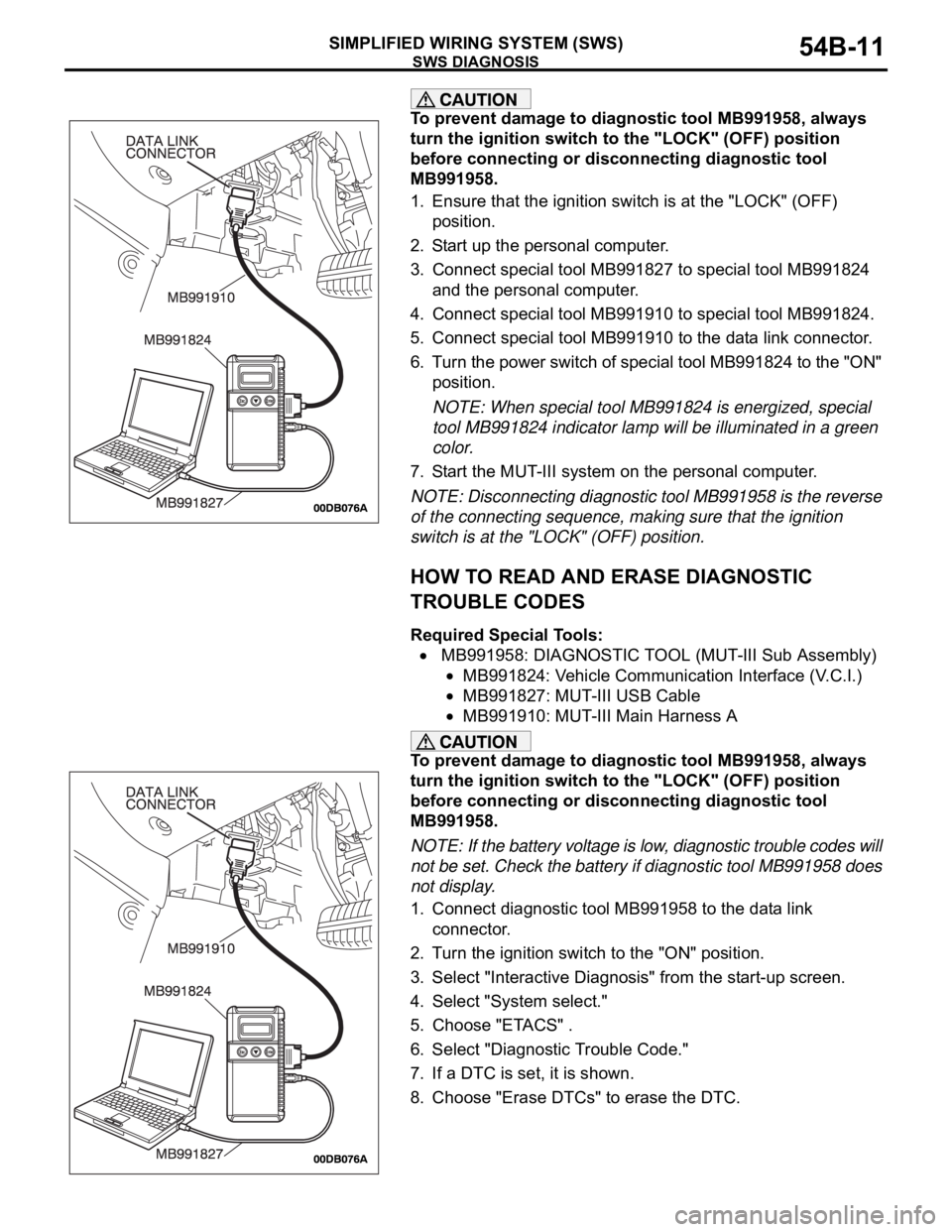
1. Ensure that the ignition switch is at the "LOCK" (OFF)
position.
2. Start up the personal computer.
3. Connect special tool MB991827 to special tool MB991824
and the personal computer.
4. Connect special tool MB991910 to special tool MB991824.
5. Connect special tool MB991910 to the data link connector.
6. Turn the power switch of special tool MB991824 to the "ON"
position.
NOTE: When special tool MB991824 is energized, special
tool MB991824 indicator lamp will be illuminated in a green
color.
7. Start the MUT-III system on the personal computer.
NOTE: Disconnecting diagnostic tool MB991958 is the reverse
of the connecting sequence, making sure that the ignition
switch is at the "LOCK" (OFF) position.
HOW TO READ AND ERASE DIAGNOSTIC
TROUBLE CODES
Required Special Tools:
MB991958: DIAGNOSTIC TOOL (MUT-III Sub Assembly)
MB991824: Vehicle Communication Interface (V.C.I.)
MB991827: MUT-III USB Cable
MB991910: MUT-III Main Harness A
To prevent damage to diagnostic tool MB991958, always
turn the ignition switch to the "LOCK" (OFF) position
before connecting or disconnecting diagnostic tool
MB991958.
NOTE: If the battery voltage is low, diagnostic trouble codes will
not be set. Check the battery if diagnostic tool MB991958 does
not display.
1. Connect diagnostic tool MB991958 to the data link
connector.
2. Turn the ignition switch to the "ON" position.
3. Select "Interactive Diagnosis" from the start-up screen.
4. Select "System select."
5. Choose "ETACS" .
6. Select "Diagnostic Trouble Code."
7. If a DTC is set, it is shown.
8. Choose "Erase DTCs" to erase the DTC.
Page 12 of 1500

SWS DIAGNOSIS
SIMPLIFIED WIRING SYSTEM (SWS)54B-12
HOW TO DIAGNOSE THE CAN BUS LINES
Required Special Tools:
MB991958: DIAGNOSTIC TOOL (MUT-III Sub Assembly)
MB991824: Vehicle Communication Interface (V.C.I.)
MB991827: MUT-III USB Cable
MB991910: MUT-III Main Harness A
To prevent damage to diagnostic tool MB991958, always
turn the ignition switch to the "LOCK" (OFF) position
before connecting or disconnecting diagnostic tool
MB991958.
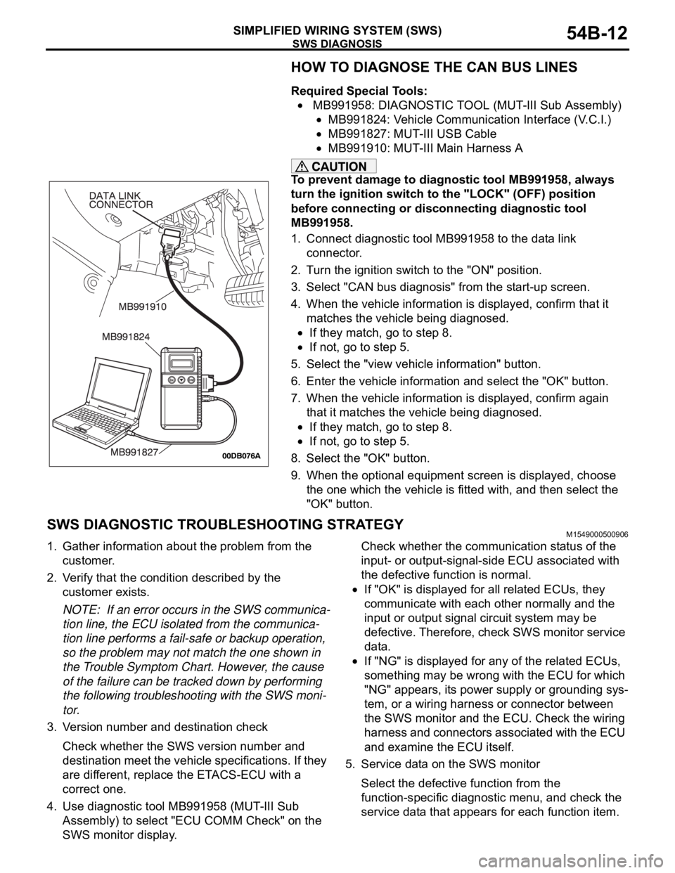
1. Connect diagnostic tool MB991958 to the data link
connector.
2. Turn the ignition switch to the "ON" position.
3. Select "CAN bus diagnosis" from the start-up screen.
4. When the vehicle information is displayed, confirm that it
matches the vehicle being diagnosed.
If they match, go to step 8.
If not, go to step 5.
5. Select the "view vehicle information" button.
6. Enter the vehicle information and select the "OK" button.
7. When the vehicle information is displayed, confirm again
that it matches the vehicle being diagnosed.
If they match, go to step 8.
If not, go to step 5.
8. Select the "OK" button.
9. When the optional equipment screen is displayed, choose
the one which the vehicle is fitted with, and then select the
"OK" button.
SWS DIAGNOSTIC TROUBLESHOOTING STRATEGYM1549000500906
1. Gather information about the problem from the
customer.
2. Verify that the condition described by the
customer exists.
NOTE: If an error occurs in the SWS communica-
tion line, the ECU isolated from the communica-
tion line performs a fail-safe or backup operation,
so the problem may not match the one shown in
the Trouble Symptom Chart. However, the cause
of the failure can be tracked down by performing
the following troubleshooting with the SWS moni-
tor.
3. Version number and destination check
Check whether the SWS version number and
destination meet the vehicle specifications. If they
are different, replace the ETACS-ECU with a
correct one.
4. Use diagnostic tool MB991958 (MUT-III Sub
Assembly) to select "ECU COMM Check" on the
SWS monitor display.Check whether the communication status of the
input- or output-signal-side ECU associated with
the defective function is normal.
If "OK" is displayed for all related ECUs, they
communicate with each other normally and the
input or output signal circuit system may be
defective. Therefore, check SWS monitor service
data.
If "NG" is displayed for any of the related ECUs,
something may be wrong with the ECU for which
"NG" appears, its power supply or grounding sys-
tem, or a wiring harness or connector between
the SWS monitor and the ECU. Check the wiring
harness and connectors associated with the ECU
and examine the ECU itself.
5. Service data on the SWS monitor
Select the defective function from the
function-specific diagnostic menu, and check the
service data that appears for each function item.
Page 13 of 1500

SWS DIAGNOSIS
SIMPLIFIED WIRING SYSTEM (SWS)54B-13
When the SWS communication line is monitored,
you can determine whether the problem lies in the
input or output signal circuit system by checking
whether communication data is correct:
If the switch condition does not meet the service
data display, the input signal is defective.
If the switch condition meets the service data dis-
play, the output signal system is defective.
Refer to circuit diagrams GROUP-90
Refer to configuration diagrams GROUP-80NOTE: In addition to the function-specific diag-
nostic menu, a service data menu is available for
SWS monitor service data to check all items for
each ECU.
6. Check the input signal circuit system
Check the relevant switch, sensor, input
signal-side ECU and their wiring harness and
connector.
7. Check the output signal circuit system
Check an output signal-side ECU, electrical load
components and their wiring harness and
connector.
HOW TO CONNECT SWS MONITORM1549014800706
Required Special Tools:
MB991958: DIAGNOSTIC TOOL (MUT-III Sub Assembly)
MB991824: Vehicle Communication Interface (V.C.I.)
MB991827: MUT-III USB Cable
MB991910: MUT-III Main Harness A
MB991813: SWS Monitor Kit
MB991806: SWS Monitor Cartridge
MB991812: SWS Monitor Harness (For Column-ECU)
MB991822: Probe Harness
To prevent damage to diagnostic tool MB991958, always
turn the ignition switch to the "LOCK" (OFF) position
before connecting or disconnecting diagnostic tool
MB991958. Connect the main harness A MB991910 before
connecting the SWS monitor harness (for column-ECU)
MB991812. Be sure to connect SWS monitor cartridge
MB991806 after turning on the V.C.I. MB991924.
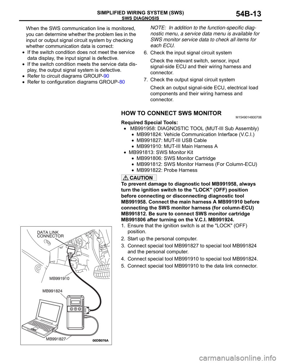
1. Ensure that the ignition switch is at the "LOCK" (OFF)
position.
2. Start up the personal computer.
3. Connect special tool MB991827 to special tool MB991824
and the personal computer.
4. Connect special tool MB991910 to special tool MB991824.
5. Connect special tool MB991910 to the data link connector.
Page 15 of 1500

SWS DIAGNOSIS
SIMPLIFIED WIRING SYSTEM (SWS)54B-15
HOW TO CHECK ECUSM1549014900640
1. Use the diagnostic tool MB991958 (MUT-III Sub
Assembly) and the SWS monitor kit to check
ECUs.
2. The following ECUs can be checked by using the
diagnostic tool MB991958 (MUT-III Sub
Assembly) and the SWS monitor kit.NOTE: The "ECU COMM Check" function checks
the communication status of ECUs. "NG" does not
always mean ECU malfunction. If a malfunction is
found by the "ECU COMM Check", proceed to
"Symptom Procedure" (Refer to P.54B-57).
SWS monitor kit-compatible ECUs and their conditions
NOTE: .
*1: If the ignition switch is turned to "LOCK" (OFF)
or "ACC" when "NG" is displayed beside "ETACS
ECU" or the signal request line is abnormal, the
diagnostic tool shows "NG" beside the "COLUMN
ECU".
*2: When "NG" is displayed beside "ETACS
ECU", the diagnostic tool shows "NG" beside the
"FRONT ECU" and "SUNROOF ECU".
SERVICE DATA CHECKM1549015000714
Use the diagnostic tool MB991958 (MUT-III Sub
Assembly) and the SWS monitor kit to check
"Data List" or "Function Diag.". This "Data List" or
"Function Diag." check is applicable for signals,
which are transmitted and received through the
SWS communication line. For input signals, which
are not compatible with the SWS monitor kit, refer
to the Pulse Check procedure (by using the
diagnostic tool or voltmeter) P.54B-24.1. The following input signals can be checked by
using the diagnostic tool MB991958 (MUT-III Sub
Assembly) and the SWS monitor kit.
NOTE: If a problem is found in the "Service Data"
check, refer to Input Signal Chart P.54B-61.
The table below shows the service data and their
normal condition, which are displayed during the
"Data List."
.
ITEM
No.ECUS TO BE
CHECKEDDISPLAY ON
DIAGNOSTIC
TOOLNORMAL
CONDITI
ONECU CONDITION
80 Column switch
(column-ECU)COLUMN ECU
OK*
1All of the column switch, power supply,
ground and interconnecting
communication lines are normal
83 ETACS-ECU ETACS-ECU OK All of the ETACS-ECU switch, power
supply, ground and interconnecting
communication lines are normal
84 Front-ECU FRONT ECU
OK*
2All of the front-ECU, power supply, ground
and interconnecting communication lines
are normal
86 Sunroof motor
assembly
(sunroof-ECU)SUNROOF ECU
OK*
2All of the sunroof motor assembly, power
supply, ground and interconnecting
communication lines are normal
Page 16 of 1500

SWS DIAGNOSIS
SIMPLIFIED WIRING SYSTEM (SWS)54B-16
COLUMN ECU
.
CHECK
ITEMITEM NO. DISPLAY ON
DIAGNOSTIC
TOOLCHECK CONDITION NORMAL
CONDITION
Dimmer
switch02 DIMMER SW Dimmer switch: ON ON
Dimmer switch: OFF OFF
Windshield
washer
switch09 FRONT
WASH.SWWindshield washer switch: ON ON
Windshield washer switch: OFF OFF
Headlamp
switch00
HEADLAMP
SWLighting switch: HEAD ON
Lighting switch: Other than HEAD OFF
Windshield
high-speed
wiper switch07 HI WIPER SW Wiper switch: HI ON
Wiper switch: Other than HI OFF
With or
without
windshield
intermittent
wiper interval
adjusting
knob15 INT WIPE
KNOBVehicles with intermittent wiper control EQUIP
Vehicles without intermittent wiper control NON
Windshield
intermittent
wiper switch05 INT WIPER SW Wiper switch: INT ON
Wiper switch: Other than INT OFF
Windshield
low-speed
wiper switch06 LO WIPER SW Wiper switch: LO ON
Wiper switch: Other than LO OFF
Windshield
mist wiper
switch08 MIST WIPER
SWWiper switch: Mist ON
Wiper switch: Other than "Mist" position OFF
Passing lamp
switch03 PASSING SW Passing lamp switch: ON ON
Passing lamp switch: OFF OFF
Ta i l l a m p
switch01 TAILLAMP SW Lighting switch: TAIL ON
Lighting switch: OFF OFF
Turn-signal
lamp switch
(LH)11 T/S LH SW Turn-signal lamp switch: LH ON
Turn-signal lamp switch: Other than LH OFF
Turn-signal
lamp switch
(RH)10 T/S RH SW Turn-signal lamp switch: RH ON
Turn-signal lamp switch: Other than RH OFF
Page 17 of 1500

SWS DIAGNOSIS
SIMPLIFIED WIRING SYSTEM (SWS)54B-17
ETACS
NOTE: For item No.43, the diagnostic tool
MB991958 (MUT-III Sub Assembly) also displays
"ON" when the lamp reminder tone alarm or the seat
belt tone alarm function is triggered.
.
CHECK
ITEMITEM NO. DISPLAY ON
DIAGNOSTIC
TOOLCHECK CONDITION NORMAL
CONDITION
Tone alarm 43 BUZZER When requirements for sounding each
warning tone alarm are not satisfiedOFF
Front fog
lamps36 F.FOG LAMP
1. Lighting switch: HEAD
2. Fog lamp switch: ONON
Other than the condition above OFF
Driver’s door
switch32 FRONT DOOR
SWDriver’s door switch and Front passenger’s
door switch is on ON
Driver’s door switch and Front passenger’s
door switch is offOFF
Headlamp
automatic
shutoff
function35 H/L AUTO-CUT
1. Lighting switch: Other than OFF
2. Ignition switch: from ON or START to
LOCK (OFF) or ACC
3. Front door switch: ON (front door open) OFF to ON (after
approximately one
second)
When requirements for the headlamp
automatic shutoff are not satisfiedOFF
Ignition
switch (ACC)31 IG SW (ACC) Ignition switch: ACC or ON ON
Ignition switch: LOCK (OFF) or START OFF
Ignition
switch (IG1)30 IG SW (IG1) Ignition switch: ON or START ON
Ignition switch: LOCK (OFF) or ACC OFF
Windshield
intermittent
wiper interval37 INT WIPE
TIME1. Ignition switch: ACC or ON
2. Operate the intermittent wiper control,
and change the wiper intervalThe diagnostic tool
MB991958
(MUT-III Sub
Assembly)
displays
intermittent wiper
interval in
response to the
intermittent wiper
control positions.