fluid MITSUBISHI 380 2005 Workshop Manual
[x] Cancel search | Manufacturer: MITSUBISHI, Model Year: 2005, Model line: 380, Model: MITSUBISHI 380 2005Pages: 1500, PDF Size: 47.87 MB
Page 254 of 1500
SYMPTOM PROCEDURES
SIMPLIFIED WIRING SYSTEM (SWS)54B-254
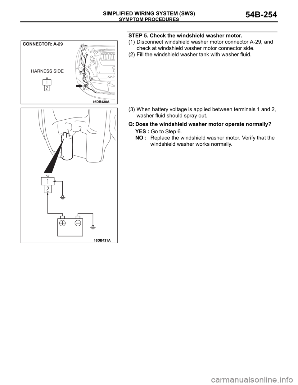
STEP 5. Check the windshield washer motor.
(1) Disconnect windshield washer motor connector A-29, and
check at windshield washer motor connector side.
(2) Fill the windshield washer tank with washer fluid.
(3) When battery voltage is applied between terminals 1 and 2,
washer fluid should spray out.
Q: Does the windshield washer motor operate normally?
YES : Go to Step 6.
NO : Replace the windshield washer motor. Verify that the
windshield washer works normally.
Page 555 of 1500
ENGINE AND TRANSMISSION
CONFIGURATION DIAGRAMS80-6
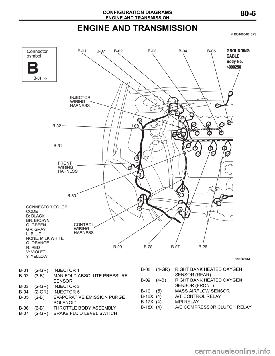
ENGINE AND TRANSMISSIONM1801000401079
B-01 (2-GR) INJECTOR 1
B-02 (3-B) MANIFOLD ABSOLUTE PRESSURE
SENSOR
B-03 (2-GR) INJECTOR 3
B-04 (2-GR) INJECTOR 5
B-05 (2-B) EVAPORATIVE EMISSION PURGE
SOLENOID
B-06 (6-B) THROTTLE BODY ASSEMBLY
B-07 (2-GR) BRAKE FLUID LEVEL SWITCHB-08 (4-GR) RIGHT BANK HEATED OXYGEN
SENSOR (REAR)
B-09 (4-B) RIGHT BANK HEATED OXYGEN
SENSOR (FRONT)
B-10 (5) MASS AIRFLOW SENSOR
B-16X (4) A/T CONTROL RELAY
B-17X (4) MPI RELAY
B-18X (4) A/C COMPRESSOR CLUTCH RELAY
Page 887 of 1500
INSPECTION TERMINAL
COMPONENT LOCATIONS70-8
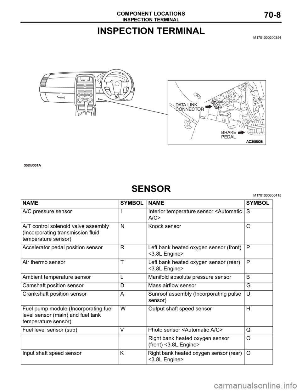
INSPECTION TERMINALM1701000200354
SENSORM1701000600415
NAME SYMBOL NAME SYMBOL
A/C pressure sensor I Interior temperature sensor
A/T control solenoid valve assembly
(Incorporating transmission fluid
temperature sensor)N Knock sensor C
Accelerator pedal position sensor R Left bank heated oxygen sensor (front)
<3.8L Engine>P
Air thermo sensor T Left bank heated oxygen sensor (rear)
<3.8L Engine>P
Ambient temperature sensor L Manifold absolute pressure sensor B
Camshaft position sensor D Mass airflow sensor G
Crankshaft position sensor A Sunroof assembly (Incorporating pulse
sensor)U
Fuel pump module (Incorporating fuel
level sensor (main) and fuel tank
temperature sensor)W Output shaft speed sensor H
Fuel level sensor (sub) V Photo sensor
Right bank heated oxygen sensor
(front) <3.8L Engine>O
Input shaft speed sensor K Right bank heated oxygen sensor (rear)
<3.8L Engine>O
Page 947 of 1500
RADIATOR
ENGINE COOLING14-32
RADIATOR
REMOVAL AND INSTALLATIONM1141001500521
Pre-removal Operation
Engine Coolant Draining (Refer to 27).
Air Cleaner Removal (Refer to GROUP 15, Air Cleaner 4).Post-installation Operation
Air Cleaner Installation (Refer to GROUP 15 4).
Engine Coolant Refilling and Level Check (Refer to 27).
A/T Fluid Refilling and Level Check (Refer to GROUP 00,
Maintenance Service 45).
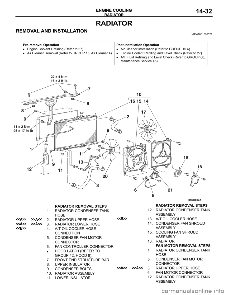
RADIATOR REMOVAL STEPS
1. RADIATOR CONDENSER TANK
HOSE
<> >>A<<2. RADIATOR UPPER HOSE
<> >>A<<3. RADIATOR LOWER HOSE
<>4. A/T OIL COOLER HOSE
CONNECTION
5. CONDENSER FAN MOTOR
CONNECTOR
6. FAN CONTROLLER CONNECTOR
HOOD LATCH (REFER TO
GROUP 42, HOOD 8).
7. FRONT END STRUCTURE BAR
8. UPPER INSULATOR
9. CONDENSER BOLTS
10. RADIATOR ASSEMBLY
11. LOWER INSULATOR12. RADIATOR CONDENSER TANK
ASSEMBLY
<>13. A/T OIL COOLER HOSE
14. CONDENSER FAN SHROUD
ASSEMBLY
15. COOLING FAN SHROUD
ASSEMBLY
16. RADIATOR
FAN MOTOR REMOVAL STEPS
1. RADIATOR CONDENSER TANK
HOSE
5. CONDENSER FAN MOTOR
CONNECTOR
<> >>A<<3. RADIATOR UPPER HOSE
6. FAN MOTOR CONNECTOR
12. RADIATOR CONDENSER TANK
ASSEMBLY RADIATOR REMOVAL STEPS
Page 1019 of 1500
GENERAL DESCRIPTION
POWER PLANT MOUNT32-2
GENERAL DESCRIPTIONM1321000100373
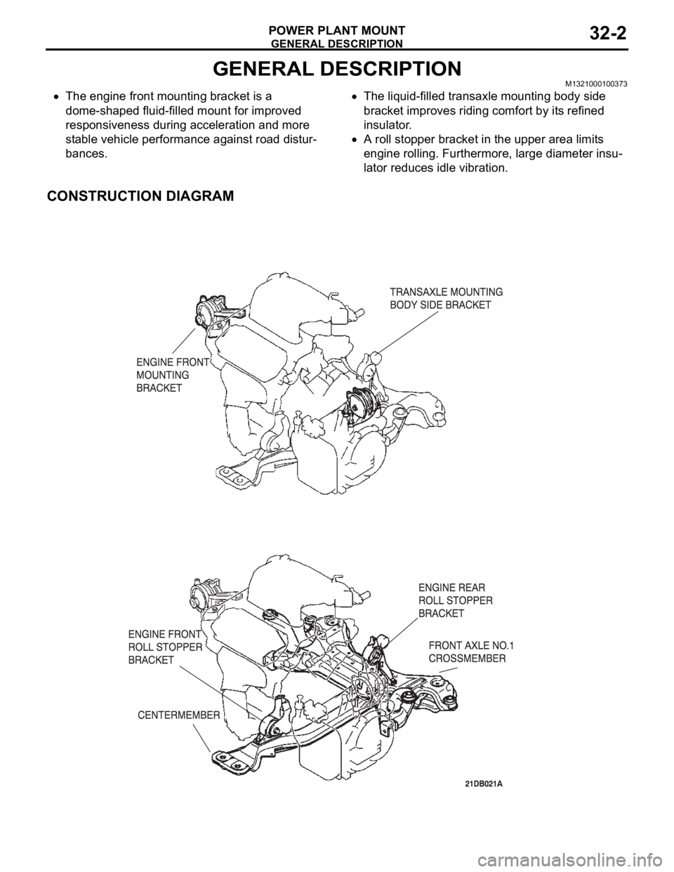
The engine front mounting bracket is a
dome-shaped fluid-filled mount for improved
responsiveness during acceleration and more
stable vehicle performance against road distur-
bances.The liquid-filled transaxle mounting body side
bracket improves riding comfort by its refined
insulator.
A roll stopper bracket in the upper area limits
engine rolling. Furthermore, large diameter insu-
lator reduces idle vibration.
CONSTRUCTION DIAGRAM
Page 1026 of 1500
CROSSMEMBER
POWER PLANT MOUNT32-9
CROSSMEMBER
REMOVAL AND INSTALLATIONM1321003200551
Before removing the steering wheel and air bag module assembly, always refer to GROUP 52B -
Service Precautions (P.52B-16), Air bag Module and Clock Spring (P.52B-237). Also, set the front
wheels so that they are facing straight forward, and remove the ignition key. If you fail to do this,
the SRS clock spring will be damaged, causing the SRS air bag to be inoperative and serious
injury.
*1: Indicates parts which should be initially tightened, and then fully tightened after placing the
vehicle horizontally and loading the full weight of the engine on the vehicle body.
*2: Indicates parts which should be temporarily tightened, and then fully tightened with the vehicle
on the ground in the unladen condition.
Pre-removal Operation
Power Steering Fluid Draining (Refer to GROUP 37,
On-vehicle Service Fluid Replacement P.37-18).
Power Steering Hoses Removal and Installation (Refer to
GROUP 37, Power Steering Hoses P.37A-57).
Air Bag Module and Steering Wheel Assembly Removal
(Refer to GROUP 37, Steering Wheel P.37-23).
Clock Spring Removal (Refer to GROUP 52B, Air Bag
Module and Clock Spring P.52B-237).
Floor Console Assembly Removal (Refer to GROUP 52A,
Floor Console Assembly P.52A-10).
Front Scuff Plate (LH) and Cowl Side Trim (LH) Removal
(Refer to GROUP 52A, Trims P.52A-11).
Trunk Lid Release Handle Cover Removal (Refer to
GROUP 42, Trunk Lid P.42-63).
Accelerator Stopper Removal (Refer to GROUP 17,
Accelerator Pedal P.17-9).
Front Floor Carpet Removal
Centremember Removal (Refer to P.32-7).Post-installation Operation
Centremember Installation (Refer to P.32-7).
Front Floor Carpet Installation
Accelerator Stopper Installation (Refer to GROUP 17,
Accelerator Pedal P.17-9).
Trunk Lid Release Handle Cover Installation (Refer to
GROUP 42, Trunk Lid P.42-63).
Front Scuff Plate (LH) and Cowl Side Trim (LH) Installa-
tion (Refer to GROUP 52A, Trims P.52A-11).
Floor Console Assembly Installation (Refer to GROUP
52A, Floor Console Assembly P.52A-10).
Clock Spring Installation (Refer to GROUP 52B, Air Bag
Module and Clock Spring P.52B-237).
Steering Wheel Assembly and Air Bag Module Installation
(Refer to P.37-23).
Check the dust cover for cracks or damage by pushing it
with your finger.
Power Steering Fluid Supplying (Refer to GROUP 37,
On-vehicle Service Fluid Replacement P.37-18).
Power Steering Fluid Line Bleeding (Refer to P.37-18).
Checking Steering Wheel Position with Wheels Straight
Ahead.
Front Wheel Alignment Adjustment (Refer to GROUP 33,
On-vehicle Service
Front Wheel Alignment Check and
Adjustment P.33-6).
Page 1034 of 1500
51-1
GROUP 51
EXTERIOR
CONTENTS
FRONT BUMPER ASSEMBLY . . . . .51-2
REMOVAL AND INSTALLATION . . . . . . . . 51-2
DISASSEMBLY AND ASSEMBLY . . . . . . . 51-3
REAR BUMPER ASSEMBLY . . . . . .51-5
REMOVAL AND INSTALLATION . . . . . . . . 51-5
RADIATOR GRILLE. . . . . . . . . . . . . .51-6
REMOVAL AND INSTALLATION . . . . . . . . 51-6
GARNISHES AND MOLDINGS . . . . .51-7
SPECIAL TOOLS . . . . . . . . . . . . . . . . . . . . 51-7
MOLDINGS . . . . . . . . . . . . . . . . . . . . . . . . . 51-8
REMOVAL AND INSTALLATION . . . . . . . . 51-8
REAR SPOILER . . . . . . . . . . . . . . . . .51-11
REMOVAL AND INSTALLATION . . . . . . . . 51-11
MUD GUARD . . . . . . . . . . . . . . . . . . .51-12
REMOVAL AND INSTALLATION . . . . . . . . 51-12
UNDER COVER . . . . . . . . . . . . . . . . .51-13
REMOVAL AND INSTALLATION . . . . . . . . 51-13
WINDSHIELD WIPER AND WASHER51-14
GENERAL DESCRIPTION . . . . . . . . . . . . . 51-14
WINDSHIELD WIPER AND WASHER DIAGNOSIS . . . . . . . . . . . . . . . . . . . . . . . . . 51-14
SPECIAL TOOLS . . . . . . . . . . . . . . . . . . . . 51-15
ON-VEHICLE SERVICE . . . . . . . . . . . . . . . 51-15
WINDSHIELD INTERMITTENT WIPER
VOLUME CHECK . . . . . . . . . . . . . . . . . . . . 51-15
WINDSHIELD WASHER FLUID EJECTION
CHECK . . . . . . . . . . . . . . . . . . . . . . . . . . . . 51-16
WINDSHIELD WIPER . . . . . . . . . . . . . . . . . 51-17
REMOVAL AND INSTALLATION . . . . . . . . 51-17
INSPECTION. . . . . . . . . . . . . . . . . . . . . . . . 51-20
WINDSHIELD WASHER . . . . . . . . . . . . . . . 51-23
REMOVAL AND INSTALLATION . . . . . . . . 51-23
INSPECTION. . . . . . . . . . . . . . . . . . . . . . . . 51-24
MARK . . . . . . . . . . . . . . . . . . . . . . . . .51-25
REMOVAL AND INSTALLATION . . . . . . . . 51-25
DOOR MIRROR . . . . . . . . . . . . . . . . .51-27
GENERAL DESCRIPTION . . . . . . . . . . . . . 51-27
DOOR MIRROR . . . . . . . . . . . . . . . . . . . . . 51-28
REMOVAL AND INSTALLATION . . . . . . . . 51-28
INSPECTION. . . . . . . . . . . . . . . . . . . . . . . . 51-29
SPECIFICATIONS . . . . . . . . . . . . . . .51-31
FASTENER TIGHTENING SPECIFICATIONS51-31
SERVICE SPECIFICATIONS . . . . . . . . . . . 51-31
ADHESIVE . . . . . . . . . . . . . . . . . . . . . . . . . 51-31
Page 1049 of 1500
WINDSHIELD WIPER AND WASHER
EXTERIOR51-16
If the windshield intermittent wiper interval control is operated,
the wiper interval should change.
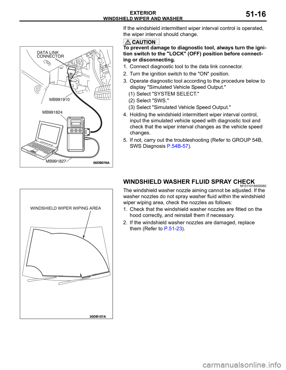
To prevent damage to diagnostic tool, always turn the igni-
tion switch to the "LOCK" (OFF) position before connect-
ing or disconnecting.
1. Connect diagnostic tool to the data link connector.
2. Turn the ignition switch to the "ON" position.
3. Operate diagnostic tool according to the procedure below to
display "Simulated Vehicle Speed Output."
(1) Select "SYSTEM SELECT."
(2) Select "SWS."
(3) Select "Simulated Vehicle Speed Output."
4. Holding the windshield intermittent wiper interval control,
input the simulated vehicle speed with diagnostic tool and
check that the wiper interval changes as the vehicle speed
changes.
5. If not, carry out the troubleshooting (Refer to GROUP 54B,
SWS Diagnosis P.54B-57).
WINDSHIELD WASHER FLUID SPRAY CHECKM1511018400060
The windshield washer nozzle aiming cannot be adjusted. If the
washer nozzles do not spray washer fluid within the windshield
wiper wiping area, check the nozzles as follows:
1. Check that the windshield washer nozzles are fitted on the
hood correctly, and reinstall them if necessary.
2. If the windshield washer nozzles are damaged, replace
them (Refer to P.51-23).
Page 1157 of 1500
GENERAL INFORMATION
CLUTCH21A-2
GENERAL INFORMATION
M1211000100234
The clutch is a dry single-disc, diaphragm type;
hydraulic pressure is used for the clutch control. The
clutch shares a brake fluid reservoir with the brake
system.
SERVICE SPECIFICATIONS
M1211000300227
LUBRICANTS
M1211000400183
ON-VEHICLE SERVICE
CLUTCH PEDAL CHECK AND
ADJUSTMENT
M1211000900285
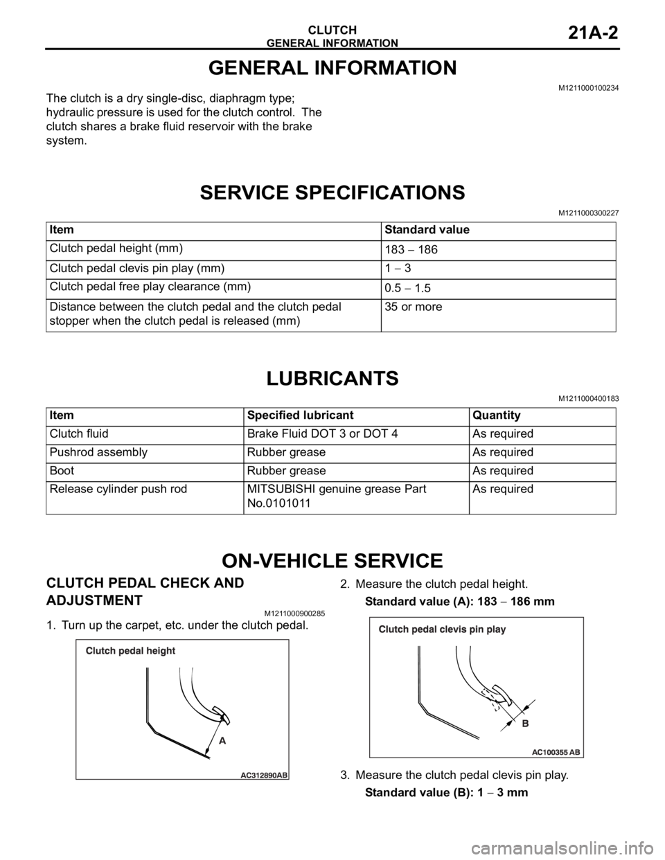
1. Turn up the carpet, etc. under the clutch pedal.2. Measure the clutch pedal height.
Standard value (A): 183
186 mm
3. Measure the clutch pedal clevis pin play.
Standard value (B): 1
3 mm Item Standard value
Clutch pedal height (mm)
183
186
Clutch pedal clevis pin play (mm) 1
3
Clutch pedal free play clearance (mm)
0.5
1.5
Distance between the clutch pedal and the clutch pedal
stopper when the clutch pedal is released (mm)35 or more
Item Specified lubricant Quantity
Clutch fluid Brake Fluid DOT 3 or DOT 4 As required
Pushrod assembly Rubber grease As required
Boot Rubber grease As required
Release cylinder push rod MITSUBISHI genuine grease Part
No.0101011As required
Page 1158 of 1500
ON-VEHICLE SERVICE
CLUTCH21A-3
Do not push in the master cylinder pushrod at
this time, otherwise the clutch will not operate
properly.
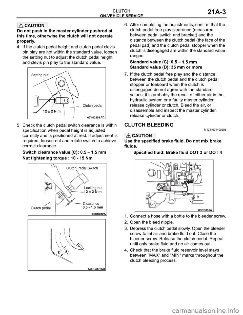
4. If the clutch pedal height and clutch pedal clevis
pin play are not within the standard value, loosen
the setting nut to adjust the clutch pedal height
and clevis pin play to the standard value.
5. Check the clutch pedal switch clearance is within
specification when pedal height is adjusted
correctly and is positioned at rest. If adjustment is
required, loosen nut and rotate switch to achieve
correct clearance.
Switch clearance value (C): 0.5
1.5 mm
Nut tightening torque : 10 - 15 Nm6. After completing the adjustments, confirm that the
clutch pedal free play clearance (measured
between pedal switch and bracket) and the
distance between the clutch pedal (the face of the
pedal pad) and the clutch pedal stopper when the
clutch is disengaged are within the standard value
ranges.
Standard value (C): 0.5
1.5 mm
Standard value (D): 35 mm or more
7. If the clutch pedal free play and the distance
between the clutch pedal and the clutch pedal
stopper or toeboard when the clutch is
disengaged do not agree with the standard
values, it is probably the result of either air in the
hydraulic system or a faulty master cylinder,
release cylinder or clutch. Bleed the air, or
disassemble and inspect the master cylinder,
release cylinder or clutch.
CLUTCH BLEEDINGM1211001400205
Use the specified brake fluid. Do not mix brake
fluids.
Specified fluid: Brake fluid DOT 3 or DOT 4
1. Connect a hose with a bottle to the bleeder screw.
2. Open the bleed nipple.
3. Depress the clutch pedal slowly. Open the bleeder
screw to let air and brake fluid out. Close the
bleeder screw. Release the clutch pedal. Repeat
until only brake fluid and no air comes out.
4. Check that the brake fluid reservoir level stays
between "MAX" and "MIN" marks throughout the
clutch bleeding process.