air conditioning MITSUBISHI 380 2005 Workshop Manual
[x] Cancel search | Manufacturer: MITSUBISHI, Model Year: 2005, Model line: 380, Model: MITSUBISHI 380 2005Pages: 1500, PDF Size: 47.87 MB
Page 43 of 1500
DIAGNOSTIC TROUBLE CODE PROCEDURES
SIMPLIFIED WIRING SYSTEM (SWS)54B-43
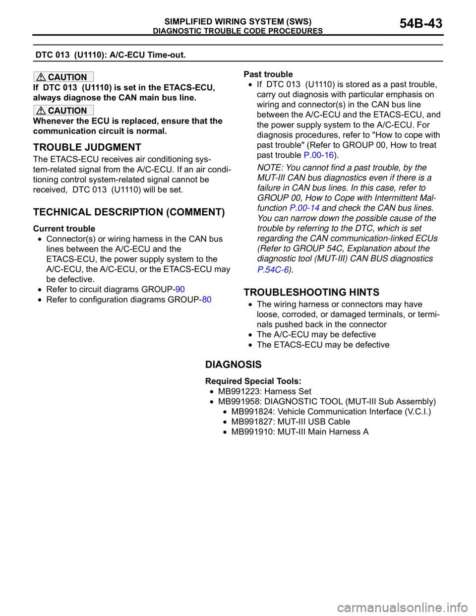
DTC 013 (U1110): A/C-ECU Time-out.
If DTC 013 (U1110) is set in the ETACS-ECU,
always diagnose the CAN main bus line.
Whenever the ECU is replaced, ensure that the
communication circuit is normal.
.
TROUBLE JUDGMENT
The ETACS-ECU receives air conditioning sys-
tem-related signal from the A/C-ECU. If an air condi-
tioning control system-related signal cannot be
received, DTC 013 (U1110) will be set.
.
TECHNICAL DESCRIPTION (COMMENT)
Current trouble
Connector(s) or wiring harness in the CAN bus
lines between the A/C-ECU and the
ETACS-ECU, the power supply system to the
A/C-ECU, the A/C-ECU, or the ETACS-ECU may
be defective.
Refer to circuit diagrams GROUP-90
Refer to configuration diagrams GROUP-80Past trouble
If DTC 013 (U1110) is stored as a past trouble,
carry out diagnosis with particular emphasis on
wiring and connector(s) in the CAN bus line
between the A/C-ECU and the ETACS-ECU, and
the power supply system to the A/C-ECU. For
diagnosis procedures, refer to "How to cope with
past trouble" (Refer to GROUP 00, How to treat
past trouble P.00-16).
NOTE: You cannot find a past trouble, by the
MUT-III CAN bus diagnostics even if there is a
failure in CAN bus lines. In this case, refer to
GROUP 00, How to Cope with Intermittent Mal-
function P.00-14 and check the CAN bus lines.
You can narrow down the possible cause of the
trouble by referring to the DTC, which is set
regarding the CAN communication-linked ECUs
(Refer to GROUP 54C, Explanation about the
diagnostic tool (MUT-III) CAN BUS diagnostics
P.54C-6).
.
TROUBLESHOOTING HINTS
The wiring harness or connectors may have
loose, corroded, or damaged terminals, or termi-
nals pushed back in the connector
The A/C-ECU may be defective
The ETACS-ECU may be defective
DIAGNOSIS
Required Special Tools:
MB991223: Harness Set
MB991958: DIAGNOSTIC TOOL (MUT-III Sub Assembly)
MB991824: Vehicle Communication Interface (V.C.I.)
MB991827: MUT-III USB Cable
MB991910: MUT-III Main Harness A
Page 44 of 1500
DIAGNOSTIC TROUBLE CODE PROCEDURES
SIMPLIFIED WIRING SYSTEM (SWS)54B-44
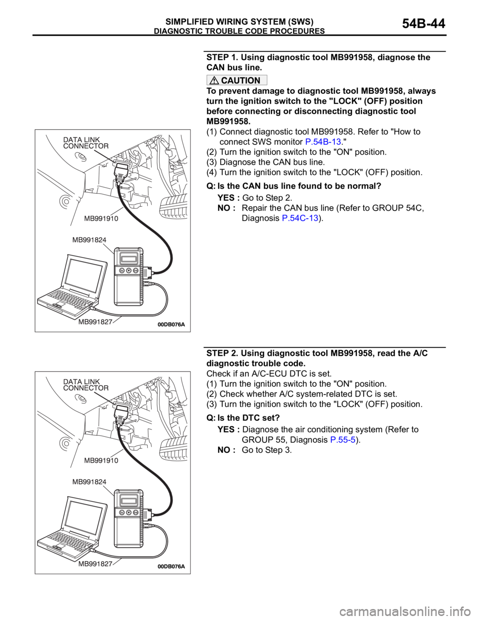
STEP 1. Using diagnostic tool MB991958, diagnose the
CAN bus line.
To prevent damage to diagnostic tool MB991958, always
turn the ignition switch to the "LOCK" (OFF) position
before connecting or disconnecting diagnostic tool
MB991958.
(1) Connect diagnostic tool MB991958. Refer to "How to
connect SWS monitor P.54B-13."
(2) Turn the ignition switch to the "ON" position.
(3) Diagnose the CAN bus line.
(4) Turn the ignition switch to the "LOCK" (OFF) position.
Q: Is the CAN bus line found to be normal?
YES : Go to Step 2.
NO : Repair the CAN bus line (Refer to GROUP 54C,
Diagnosis P.54C-13).
STEP 2. Using diagnostic tool MB991958, read the A/C
diagnostic trouble code.
Check if an A/C-ECU DTC is set.
(1) Turn the ignition switch to the "ON" position.
(2) Check whether A/C system-related DTC is set.
(3) Turn the ignition switch to the "LOCK" (OFF) position.
Q: Is the DTC set?
YES : Diagnose the air conditioning system (Refer to
GROUP 55, Diagnosis P.55-5).
NO : Go to Step 3.
Page 498 of 1500
INSTRUMENT PANEL ASSEMBLY
INTERIOR52A-9
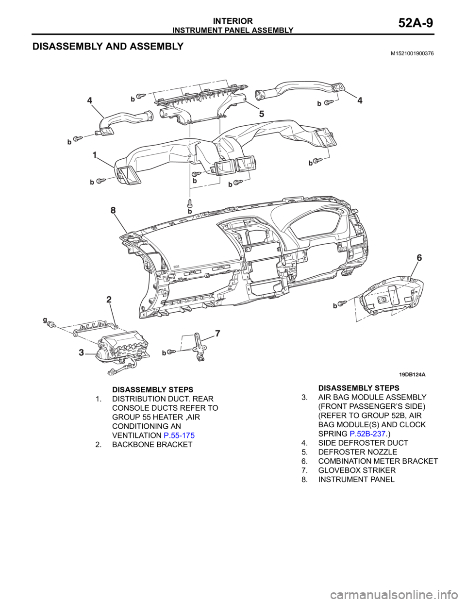
DISASSEMBLY AND ASSEMBLYM1521001900376
DISASSEMBLY STEPS
1. DISTRIBUTION DUCT. REAR
CONSOLE DUCTS REFER TO
GROUP 55 HEATER ,AIR
CONDITIONING AN
VENTILATION P.55-175
2. BACKBONE BRACKET3. AIR BAG MODULE ASSEMBLY
(FRONT PASSENGER’S SIDE)
(REFER TO GROUP 52B, AIR
BAG MODULE(S) AND CLOCK
SPRING P.52B-237.)
4. SIDE DEFROSTER DUCT
5. DEFROSTER NOZZLE
6. COMBINATION METER BRACKET
7. GLOVEBOX STRIKER
8. INSTRUMENT PANELDISASSEMBLY STEPS
Page 576 of 1500

55-1
GROUP 55
HEATER, AIR
CONDITIONING AND
VENTILATION
CONTENTS
HEATER, AIR CONDITIONING AND VENTILATION. . . . . . . . .55
Page 579 of 1500
CIRCUIT DIAGRAMS90-2
AUTOMATIC AIR CONDITIONING
SYSTEM . . . . . . . . . . . . . . . . . . . . . . .90-71
WINDSHIELD WIPER AND WASHER90-75
REAR WINDOW DEFOGGER . . . . . .90-78
REMOTE CONTROLLED MIRROR . .90-79
AUDIO SYSTEM . . . . . . . . . . . . . . . .90-80
ACCESSORY SOCKET . . . . . . . . . . .90-82
CLOCK DISPLAY . . . . . . . . . . . . . . .90-83
MULTI-CENTER DISPLAY . . . . . . . .90-84
SUNROOF . . . . . . . . . . . . . . . . . . . . .90-87
AUTO-CRUISE CONTROL SYSTEM90-89
ANTI-LOCK BRAKING SYSTEM (ABS)
ANTI-LOCK BRAKING SYSTEM (ABS)
SYSTEM (SRS) . . . . . . . . . . . . . . . . . .90-99
ENGINE IMMOBILISER SYSTEM . . .90-103
POWER SEAT WITH MEMORY
(DRIVER). . . . . . . . . . . . . . . . . . . . . . .90-104
POWER SEAT (8-WAY)
(DRIVER AND PASSENGER) . . . . . .90-106
POWER SEAT [(6-WAY) DRIVER] . .90-108
FORGOTTEN KEY PREVENTION
FUNCTION . . . . . . . . . . . . . . . . . . . . .90-109
LIGHTING MONITOR TONE ALARM90-111
IGNITION KEY REMINDER TONE
ALARM . . . . . . . . . . . . . . . . . . . . . . . .90-112
SEAT BELT WARNING TONE
ALARM . . . . . . . . . . . . . . . . . . . . . . . .90-113
DOOR AJAR WARNING TONE
ALARM . . . . . . . . . . . . . . . . . . . . . . . .90-115
RHEOSTAT . . . . . . . . . . . . . . . . . . . . .90-118
CONTROLLER AREA NETWORK
(CAN) . . . . . . . . . . . . . . . . . . . . . . . . .90-119
Page 648 of 1500
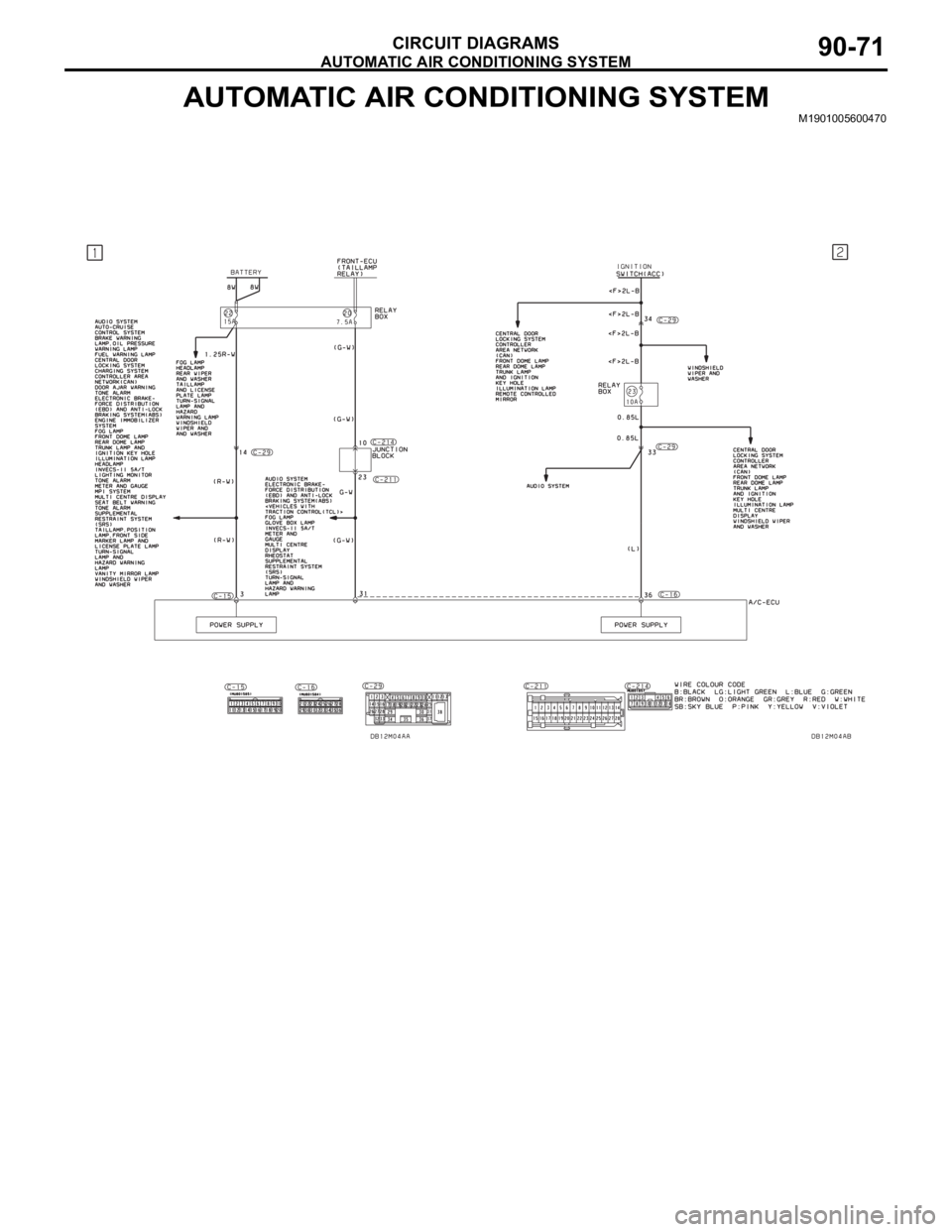
AUTOMATIC AIR CONDITIONING SYSTEM
CIRCUIT DIAGRAMS90-71
AUTOMATIC AIR CONDITIONING SYSTEMM1901005600470
Page 649 of 1500
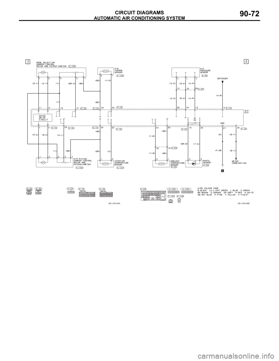
AUTOMATIC AIR CONDITIONING SYSTEM
CIRCUIT DIAGRAMS90-72
Page 650 of 1500
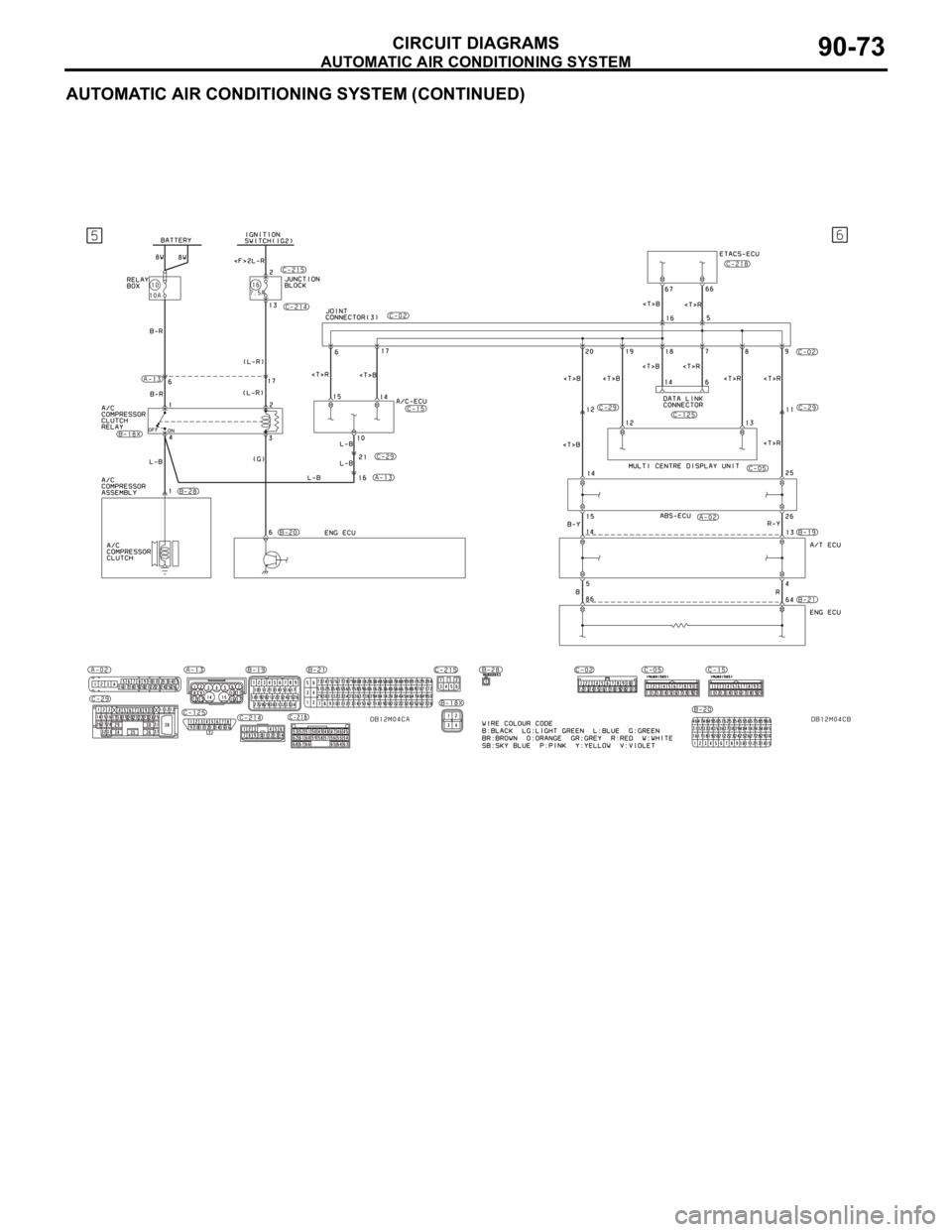
AUTOMATIC AIR CONDITIONING SYSTEM
CIRCUIT DIAGRAMS90-73
AUTOMATIC AIR CONDITIONING SYSTEM (CONTINUED)
Page 651 of 1500
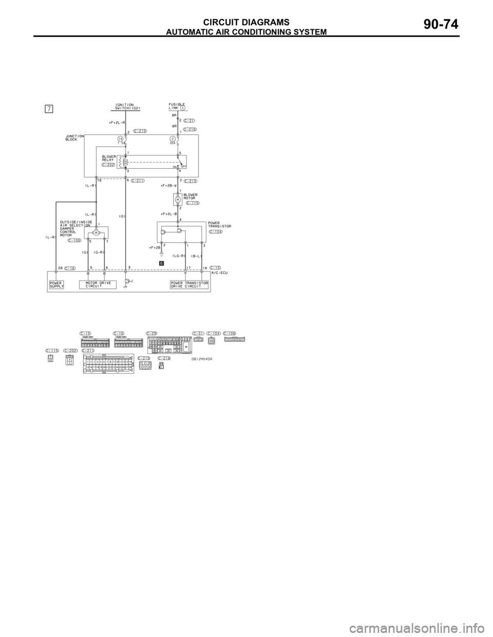
AUTOMATIC AIR CONDITIONING SYSTEM
CIRCUIT DIAGRAMS90-74
Page 702 of 1500
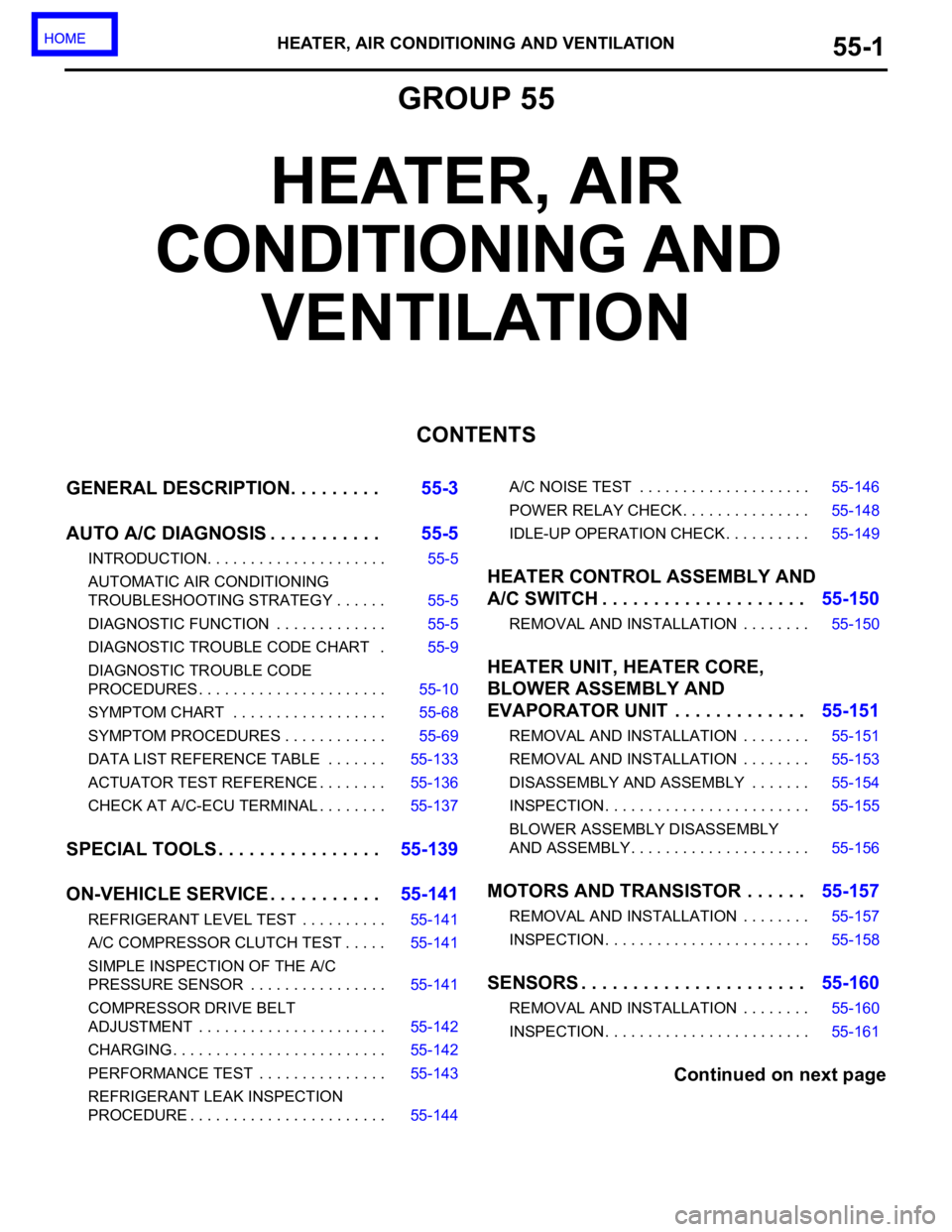
HEATER, AIR CONDITIONING AND VENTILATION55-1
GROUP 55
HEATER, AIR
CONDITIONING AND
VENTILATION
CONTENTS
GENERAL DESCRIPTION. . . . . . . . .55-3
AUTO A/C DIAGNOSIS . . . . . . . . . . .55-5
INTRODUCTION. . . . . . . . . . . . . . . . . . . . . 55-5
AUTOMATIC AIR CONDITIONING
TROUBLESHOOTING STRATEGY . . . . . . 55-5
DIAGNOSTIC FUNCTION . . . . . . . . . . . . . 55-5
DIAGNOSTIC TROUBLE CODE CHART . 55-9
DIAGNOSTIC TROUBLE CODE
PROCEDURES . . . . . . . . . . . . . . . . . . . . . . 55-10
SYMPTOM CHART . . . . . . . . . . . . . . . . . . 55-68
SYMPTOM PROCEDURES . . . . . . . . . . . . 55-69
DATA LIST REFERENCE TABLE . . . . . . . 55-133
ACTUATOR TEST REFERENCE . . . . . . . . 55-136
CHECK AT A/C-ECU TERMINAL . . . . . . . . 55-137
SPECIAL TOOLS . . . . . . . . . . . . . . . .55-139
ON-VEHICLE SERVICE . . . . . . . . . . .55-141
REFRIGERANT LEVEL TEST . . . . . . . . . . 55-141
A/C COMPRESSOR CLUTCH TEST . . . . . 55-141
SIMPLE INSPECTION OF THE A/C
PRESSURE SENSOR . . . . . . . . . . . . . . . . 55-141
COMPRESSOR DRIVE BELT
ADJUSTMENT . . . . . . . . . . . . . . . . . . . . . . 55-142
CHARGING . . . . . . . . . . . . . . . . . . . . . . . . . 55-142
PERFORMANCE TEST . . . . . . . . . . . . . . . 55-143
REFRIGERANT LEAK INSPECTION
PROCEDURE . . . . . . . . . . . . . . . . . . . . . . . 55-144A/C NOISE TEST . . . . . . . . . . . . . . . . . . . . 55-146
POWER RELAY CHECK . . . . . . . . . . . . . . . 55-148
IDLE-UP OPERATION CHECK . . . . . . . . . . 55-149
HEATER CONTROL ASSEMBLY AND
A/C SWITCH . . . . . . . . . . . . . . . . . . . .55-150
REMOVAL AND INSTALLATION . . . . . . . . 55-150
HEATER UNIT, HEATER CORE,
BLOWER ASSEMBLY AND
EVAPORATOR UNIT . . . . . . . . . . . . .55-151
REMOVAL AND INSTALLATION . . . . . . . . 55-151
REMOVAL AND INSTALLATION . . . . . . . . 55-153
DISASSEMBLY AND ASSEMBLY . . . . . . . 55-154
INSPECTION. . . . . . . . . . . . . . . . . . . . . . . . 55-155
BLOWER ASSEMBLY DISASSEMBLY
AND ASSEMBLY . . . . . . . . . . . . . . . . . . . . . 55-156
MOTORS AND TRANSISTOR . . . . . .55-157
REMOVAL AND INSTALLATION . . . . . . . . 55-157
INSPECTION. . . . . . . . . . . . . . . . . . . . . . . . 55-158
SENSORS . . . . . . . . . . . . . . . . . . . . . .55-160
REMOVAL AND INSTALLATION . . . . . . . . 55-160
INSPECTION. . . . . . . . . . . . . . . . . . . . . . . . 55-161
Continued on next page