multi-center MITSUBISHI 380 2005 Workshop Manual
[x] Cancel search | Manufacturer: MITSUBISHI, Model Year: 2005, Model line: 380, Model: MITSUBISHI 380 2005Pages: 1500, PDF Size: 47.87 MB
Page 488 of 1500

ON-VEHICLE SERVICE
SIMPLIFIED WIRING SYSTEM (SWS)54B-488
ITEM (multi-center display) ADJUSTMENT DETAILS
Lamps Headlamp auto-cutout functionThe headlamp automatic shutoff function can
be set in the following ways.
a. Auto-cutout only when the ignition is turned
OFF and drivers side door is open while
lamps are on (default- 1 minute timer)
b. Auto-cutout when ignition is turned OFF
and driver side door is open at any time
(adjustable- 3 minute timer)
c. No auto-cutout (adjustable)
Dome lamp cutout time The interior dimmer delay period can be set in
the following ways.
a. 0 second
b. 15 seconds
c. 30 seconds (default)
d. 60 seconds
e. 120 seconds
f. 180 seconds
Interior lamp auto-cutout time The period before the interior illumination is
turned off automatically can be set in the
following ways.
a. 3 minutes
b. 30 minutes (default)
c. 60 minutes
d. No auto-cutout
Wipers Windshield wiper speed-sensitive
operationThe speed-sensitive wiper function can be
activated or deactivated. (ON by default)
Page 489 of 1500

ON-VEHICLE SERVICE
SIMPLIFIED WIRING SYSTEM (SWS)54B-489
Keyless entry and
power door lock
systemKeyless entry system confirmation
by hornThe horn answerback honking conditions can
be set in the following ways.
a. Horn sounds
b. Horn sounds if doors are already locked
c. Horn does not sound (default)
Keyless entry system confirmation
by turn-signal lampsThe hazard answerback flashing conditions
can be set in the following ways.
a. Locking and unlocking (default)
b. Locking only
c. Unlocking only
d. No indication
Time until automatic relocking after
unlock operation using keyless
entry systemThe timed lock period after unlocking with the
keyless entry transmitter can be set to the
following times.
a. 30 seconds (default)
b. 60 seconds
c. 120 seconds
d. 180 seconds
Unlock operation using keyless
entry system or door keyThe unlocking operations after unlocking with
or without a key can be set in the following
ways.
a. Unlock driver's door on first unlock
operation, and unlock all doors on second
unlock operation (default)
b. Unlock all doors on first unlock operation
Buzzers Turn-signal buzzer The turn-signal buzzer function can be
activated or deactivated. (OFF by default)
Door-ajar warning buzzer The door ajar warning buzzer function can be
activated or deactivated (ON by default).
Default Initialization of above mentioned functions ITEM (multi-center display) ADJUSTMENT DETAILS
Page 495 of 1500
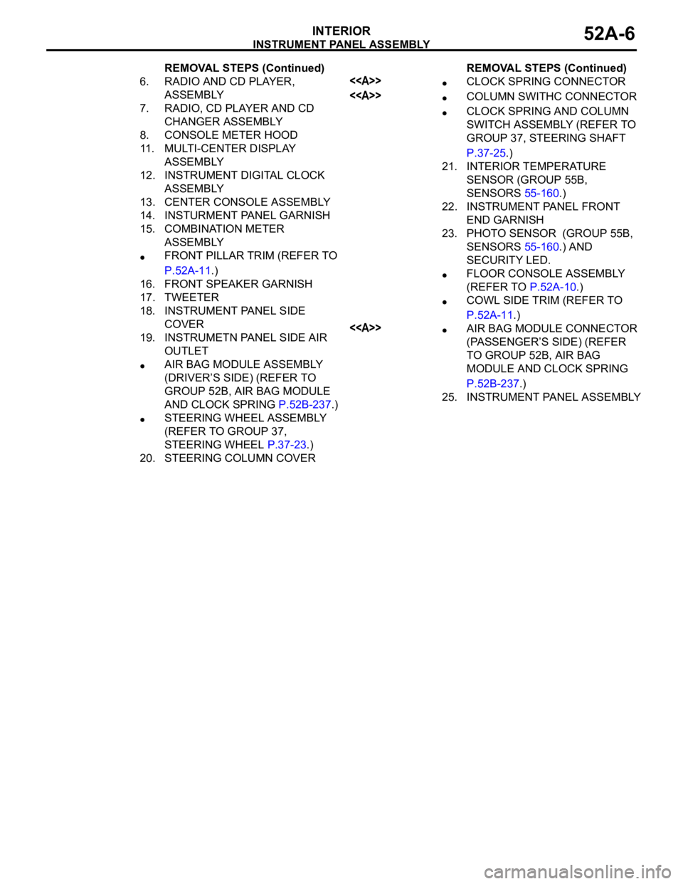
INSTRUMENT PANEL ASSEMBLY
INTERIOR52A-6
6. RADIO AND CD PLAYER,
ASSEMBLY
7. RADIO, CD PLAYER AND CD
CHANGER ASSEMBLY
8. CONSOLE METER HOOD
11. MULTI-CENTER DISPLAY
ASSEMBLY
12. INSTRUMENT DIGITAL CLOCK
ASSEMBLY
13. CENTER CONSOLE ASSEMBLY
14. INSTURMENT PANEL GARNISH
15. COMBINATION METER
ASSEMBLY
FRONT PILLAR TRIM (REFER TO
P.52A-11.)
16. FRONT SPEAKER GARNISH
17. TWEETER
18. INSTRUMENT PANEL SIDE
COVER
19. INSTRUMETN PANEL SIDE AIR
OUTLET
AIR BAG MODULE ASSEMBLY
(DRIVER’S SIDE) (REFER TO
GROUP 52B, AIR BAG MODULE
AND CLOCK SPRING P.52B-237.)
STEERING WHEEL ASSEMBLY
(REFER TO GROUP 37,
STEERING WHEEL P.37-23.)
20. STEERING COLUMN COVERREMOVAL STEPS (Continued)
<>CLOCK SPRING CONNECTOR
<>COLUMN SWITHC CONNECTOR
CLOCK SPRING AND COLUMN
SWITCH ASSEMBLY (REFER TO
GROUP 37, STEERING SHAFT
P.37-25.)
21. INTERIOR TEMPERATURE
SENSOR (GROUP 55B,
SENSORS 55-160.)
22. INSTRUMENT PANEL FRONT
END GARNISH
23. PHOTO SENSOR (GROUP 55B,
SENSORS 55-160.) AND
SECURITY LED.
FLOOR CONSOLE ASSEMBLY
(REFER TO P.52A-10.)
COWL SIDE TRIM (REFER TO
P.52A-11.)
<>AIR BAG MODULE CONNECTOR
(PASSENGER’S SIDE) (REFER
TO GROUP 52B, AIR BAG
MODULE AND CLOCK SPRING
P.52B-237.)
25. INSTRUMENT PANEL ASSEMBLYREMOVAL STEPS (Continued)
Page 579 of 1500
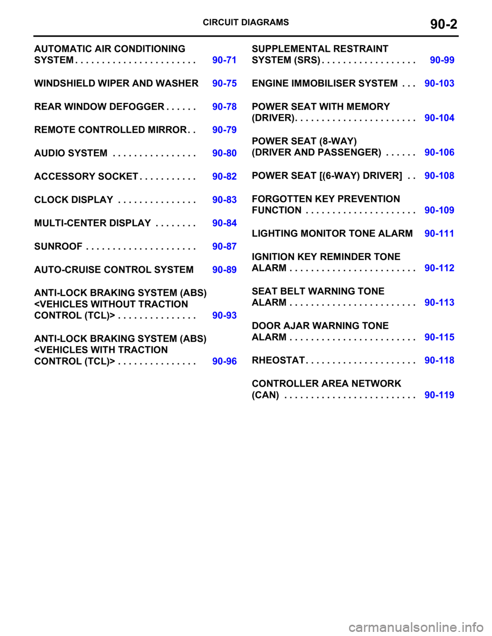
CIRCUIT DIAGRAMS90-2
AUTOMATIC AIR CONDITIONING
SYSTEM . . . . . . . . . . . . . . . . . . . . . . .90-71
WINDSHIELD WIPER AND WASHER90-75
REAR WINDOW DEFOGGER . . . . . .90-78
REMOTE CONTROLLED MIRROR . .90-79
AUDIO SYSTEM . . . . . . . . . . . . . . . .90-80
ACCESSORY SOCKET . . . . . . . . . . .90-82
CLOCK DISPLAY . . . . . . . . . . . . . . .90-83
MULTI-CENTER DISPLAY . . . . . . . .90-84
SUNROOF . . . . . . . . . . . . . . . . . . . . .90-87
AUTO-CRUISE CONTROL SYSTEM90-89
ANTI-LOCK BRAKING SYSTEM (ABS)
ANTI-LOCK BRAKING SYSTEM (ABS)
SYSTEM (SRS) . . . . . . . . . . . . . . . . . .90-99
ENGINE IMMOBILISER SYSTEM . . .90-103
POWER SEAT WITH MEMORY
(DRIVER). . . . . . . . . . . . . . . . . . . . . . .90-104
POWER SEAT (8-WAY)
(DRIVER AND PASSENGER) . . . . . .90-106
POWER SEAT [(6-WAY) DRIVER] . .90-108
FORGOTTEN KEY PREVENTION
FUNCTION . . . . . . . . . . . . . . . . . . . . .90-109
LIGHTING MONITOR TONE ALARM90-111
IGNITION KEY REMINDER TONE
ALARM . . . . . . . . . . . . . . . . . . . . . . . .90-112
SEAT BELT WARNING TONE
ALARM . . . . . . . . . . . . . . . . . . . . . . . .90-113
DOOR AJAR WARNING TONE
ALARM . . . . . . . . . . . . . . . . . . . . . . . .90-115
RHEOSTAT . . . . . . . . . . . . . . . . . . . . .90-118
CONTROLLER AREA NETWORK
(CAN) . . . . . . . . . . . . . . . . . . . . . . . . .90-119
Page 590 of 1500

CENTRALISED JUNCTION
CIRCUIT DIAGRAMS90-13
19 Front-ECU (Field
effect transistor for
headlamp: Low)Fuse 10 Red Headlamp (LH) and headlamp (Low:
LH)
20 Front-ECU (Taillamp
relay)7.5 Brown A/C-ECU, A/T selector lever position
illumination lamp, combination meter,
fog lamp switch, headlamp (RH),
glove box lamp, hazard warning lamp
switch, multi-center display unit,
radio, CD player, rear combination
lamp (RH), rheostat and TCL switch
21 7.5 Brown Headlamp (LH), license plate lamp
and rear combination lamp (LH)
22 Battery/Alternator
(Fusible link No.27)15 Blue A/C-ECU, column switch,
combination meter, ETACS-ECU,
front-ECU, key reminder switch, multi-
center display unit, radio, CD player,
and vanity mirror lamp
23 Ignition switch (ACC) 10 Red A/C-ECU, accessory socket relay,
ETACS-ECU, multi-center display
unit, radio, CD player.
24 Battery/Alternator
(Fusible link No.27)15 Blue Fuel pump module
25 Ignition switch (ACC) 30 Green Front-ECU and windshield wiper
motor
26 Battery/Alternator
(Fusible link No.27)Fusible
link20 Light blue Anti-lock braking system(solenoid
valve)
27
Alternator120
Battery, front-ECU, fusible link Nos.1,
2, 3, 4, 5 and 26 and fuse Nos.6, 7, 8,
9, 10, 11, 13, 14, 15, 22 and 24 (in
relay box) NO. POWER SUPPLY
CIRCUITNAME RATED
CAPACITY (A)HOUSING
COLOURLOAD CIRCUIT
Page 592 of 1500

CENTRALISED JUNCTION
CIRCUIT DIAGRAMS90-15
NO. POWER SUPPLY
CIRCUITNAME RATED
CAPACITY (A)HOUSING
COLOURLOAD CIRCUIT
1 Fusible link No.1 Fuse 30 Green Rear window demister
2 30 Green Blower motor and resistor
3
4
5 15 Blue Accessory socket
6 15 Blue Data link connector and ETACS-ECU
7 Ignition switch (ACC) 15 Blue ETACS-ECU
8
9 Ignition switch (IG2) 7.5 Brown Sunroof assembly
10 Ignition switch (ACC) 7.5 Brown Remote controlled mirror
11
12
13 Ignition switch (IG1) 7.5 Brown Fuel pump relay and Engine ECU
14 Ignition switch (ACC) 20 Yellow Windscreen wiper
15 Fusible link No.1
(Fuse No.5 in junction
block)7.5 Brown Remote controlled mirror
16 Ignition switch (IG2) 7.5 Brown A/C compressor clutch relay,
A/C-ECU, blower relay, condenser
fan motor, fan control relay,
front-ECU, outside/inside air selection
damper control motor and rear
window defogger relay
17 Ignition switch (IG1)
18 7.5 Brown A/T control relay, input shaft speed
sensor, output shaft speed sensor,
Engine ECU, rear combination lamp
and SRS-ECU
19 7.5 Brown ABS-ECU, ABS/TCL-ECU, column
switch, combination meter,
ETACS-ECU, multi-center display unit
and SRS-ECU
20 10 Red Ignition coil
21
22
23 Fusible link No.5 20 Yellow Sunroof assembly
24
Page 661 of 1500
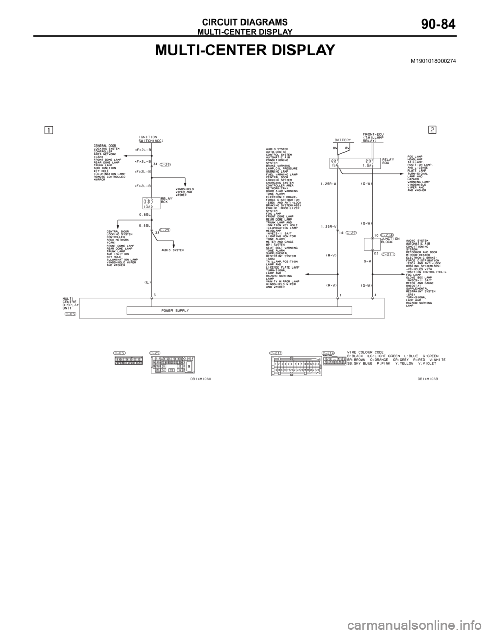
MULTI-CENTER DISPLAY
CIRCUIT DIAGRAMS90-84
MULTI-CENTER DISPLAYM1901018000274
Page 662 of 1500
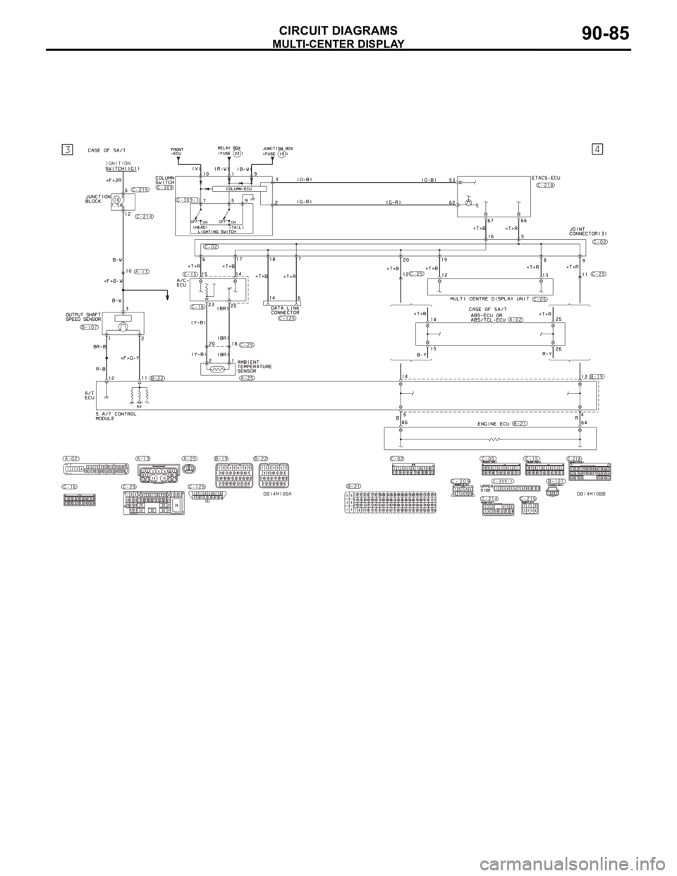
MULTI-CENTER DISPLAY
CIRCUIT DIAGRAMS90-85
Page 663 of 1500

MULTI-CENTER DISPLAY
CIRCUIT DIAGRAMS90-86
MULTI-CENTER DISPLAY (CONTINUED)
Page 761 of 1500
AUTO A/C DIAGNOSIS
HEATER, AIR CONDITIONING AND VENTILATION55-60
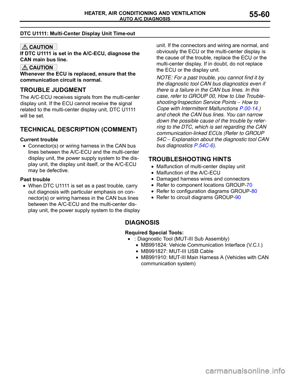
DTC U1111: Multi-Center Display Unit Time-out
If DTC U1111 is set in the A/C-ECU, diagnose the
CAN main bus line.
Whenever the ECU is replaced, ensure that the
communication circuit is normal.
.
TROUBLE JUDGMENT
The A/C-ECU receives signals from the multi-center
display unit. If the ECU cannot receive the signal
r e l a t e d t o t h e m u l t i - c e n t e r d i s p l a y u n i t , D T C U 1111
will be set.
.
TECHNICAL DESCRIPTION (COMMENT)
Current trouble
Connector(s) or wiring harness in the CAN bus
lines between the A/C-ECU and the multi-center
display unit, the power supply system to the dis-
play unit, the display unit itself, or the A/C-ECU
may be defective.
Past trouble
W h e n D T C U 1111 i s s e t a s a p a s t t r o u b l e , c a r r y
out diagnosis with particular emphasis on con-
nector(s) or wiring harness in the CAN bus lines
between the A/C-ECU and the multi-center dis-
play unit, the power supply system to the display unit. If the connectors and wiring are normal, and
obviously the ECU or the multi-center display is
the cause of the trouble, replace the ECU or the
multi-center display. If in doubt, do not replace
the ECU or the display unit.
NOTE: For a past trouble, you cannot find it by
the diagnostic tool CAN bus diagnostics even if
there is a failure in the CAN bus lines. In this
case, refer to GROUP 00, How to Use Trouble-
shooting/Inspection Service Points
How to
Cope with Intermittent Malfunctions P.00-14.)
and check the CAN bus lines. You can narrow
down the possible cause of the trouble by refer-
ring to the DTC, which is set regarding the CAN
communication-linked ECUs (Refer to GROUP
54C
Explanation about the diagnostic tool CAN
bus diagnostics P.54C-6).
.
TROUBLESHOOTING HINTS
Malfunction of multi-center display unit
Malfunction of the A/C-ECU
Damaged harness wires and connectors
Refer to component locations GROUP-70
Refer to configuration diagrams GROUP-80
Refer to circuit diagrams GROUP-90
DIAGNOSIS
Required Special Tools:
: Diagnostic Tool (MUT-III Sub Assembly)
MB991824: Vehicle Communication Interface (V.C.I.)
MB991827: MUT-III USB Cable
MB991910: MUT-III Main Harness A (Vehicles with CAN
communication system)