multi-center MITSUBISHI 380 2005 User Guide
[x] Cancel search | Manufacturer: MITSUBISHI, Model Year: 2005, Model line: 380, Model: MITSUBISHI 380 2005Pages: 1500, PDF Size: 47.87 MB
Page 762 of 1500

AUTO A/C DIAGNOSIS
HEATER, AIR CONDITIONING AND VENTILATION55-61
STEP 1. Using diagnostic tool , diagnose the CAN bus line.
To prevent damage to diagnostic tool (MUT-III), always turn
the ignition switch to the "LOCK" (OFF) position before
connecting or disconnecting diagnostic tool (MUT-III).
(1) Connect diagnostic tool to the data link connector.
(2) Turn the ignition switch to the "ON" position.
(3) Diagnose the CAN bus line.
(4) Turn the ignition switch to the "LOCK" (OFF) position.
Q: Is the CAN bus line found to be normal?
YES : Go to Step 2.
NO : Repair the CAN bus line (Refer to GROUP 54C,
Diagnosis P.54C-15).
STEP 2. Using diagnostic tool , read the Electronic control
unit diagnostic trouble code.
Check that the multi-center display unit sets a DTC.
(1) Turn the ignition switch to the "ON" position.
(2) Check for the DTC related to the multi-center display unit.
(3) Turn the ignition switch to the "LOCK" (OFF) position.
Q: Is the check result satisfactory?
YES : Refer to GROUP 54A, multi-center display unit
Diagnosis P.54A-254.
NO : Go to Step 3.
Page 763 of 1500
AUTO A/C DIAGNOSIS
HEATER, AIR CONDITIONING AND VENTILATION55-62
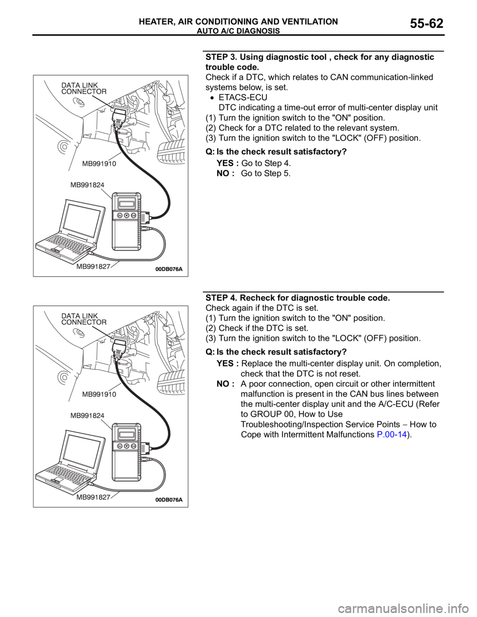
STEP 3. Using diagnostic tool , check for any diagnostic
trouble code.
Check if a DTC, which relates to CAN communication-linked
systems below, is set.
ETACS-ECU
DTC indicating a time-out error of multi-center display unit
(1) Turn the ignition switch to the "ON" position.
(2) Check for a DTC related to the relevant system.
(3) Turn the ignition switch to the "LOCK" (OFF) position.
Q: Is the check result satisfactory?
YES : Go to Step 4.
NO : Go to Step 5.
STEP 4. Recheck for diagnostic trouble code.
Check again if the DTC is set.
(1) Turn the ignition switch to the "ON" position.
(2) Check if the DTC is set.
(3) Turn the ignition switch to the "LOCK" (OFF) position.
Q: Is the check result satisfactory?
YES : Replace the multi-center display unit. On completion,
check that the DTC is not reset.
NO : A poor connection, open circuit or other intermittent
malfunction is present in the CAN bus lines between
the multi-center display unit and the A/C-ECU (Refer
to GROUP 00, How to Use
Troubleshooting/Inspection Service Points
How to
Cope with Intermittent Malfunctions P.00-14).
Page 764 of 1500
AUTO A/C DIAGNOSIS
HEATER, AIR CONDITIONING AND VENTILATION55-63
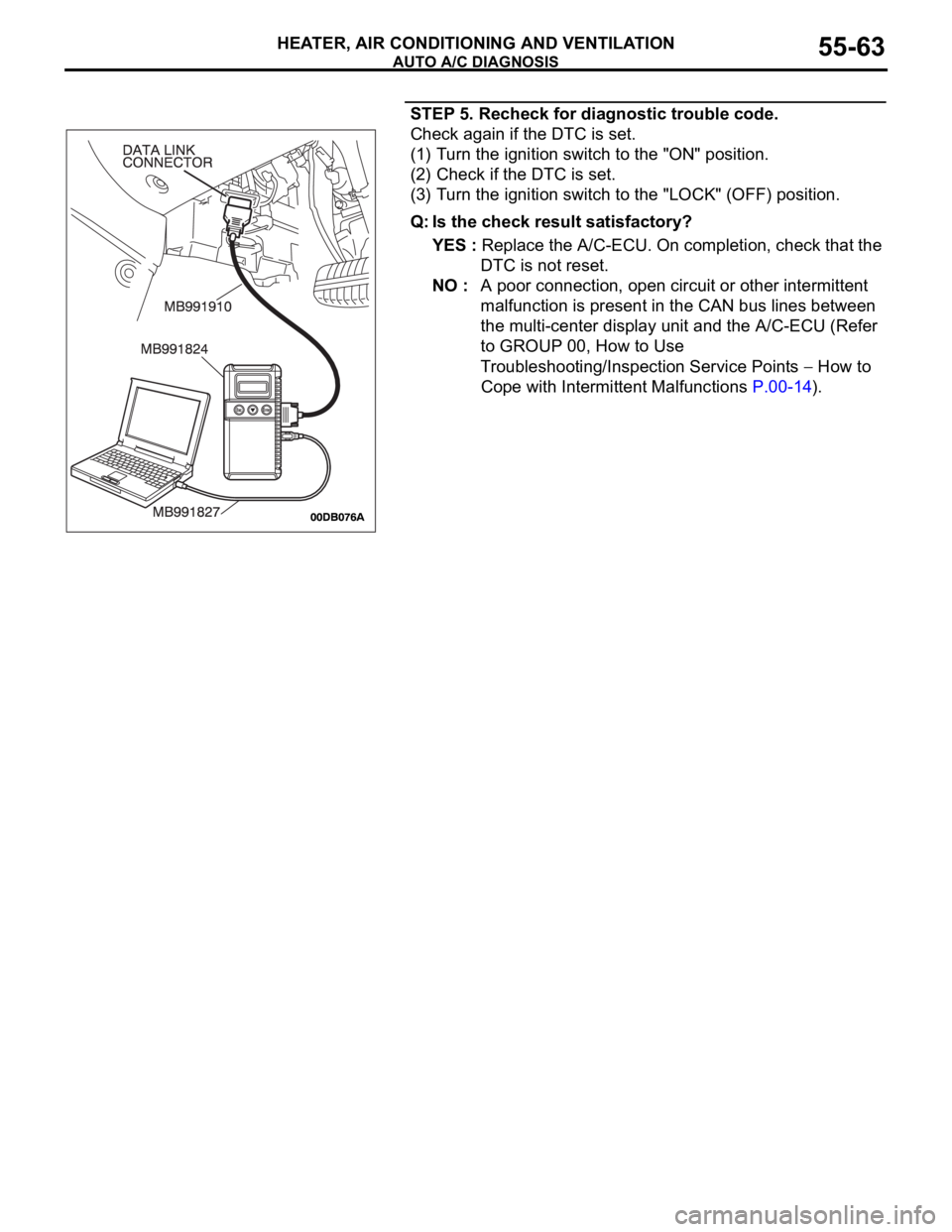
STEP 5. Recheck for diagnostic trouble code.
Check again if the DTC is set.
(1) Turn the ignition switch to the "ON" position.
(2) Check if the DTC is set.
(3) Turn the ignition switch to the "LOCK" (OFF) position.
Q: Is the check result satisfactory?
YES : Replace the A/C-ECU. On completion, check that the
DTC is not reset.
NO : A poor connection, open circuit or other intermittent
malfunction is present in the CAN bus lines between
the multi-center display unit and the A/C-ECU (Refer
to GROUP 00, How to Use
Troubleshooting/Inspection Service Points
How to
Cope with Intermittent Malfunctions P.00-14).
Page 767 of 1500
AUTO A/C DIAGNOSIS
HEATER, AIR CONDITIONING AND VENTILATION55-66
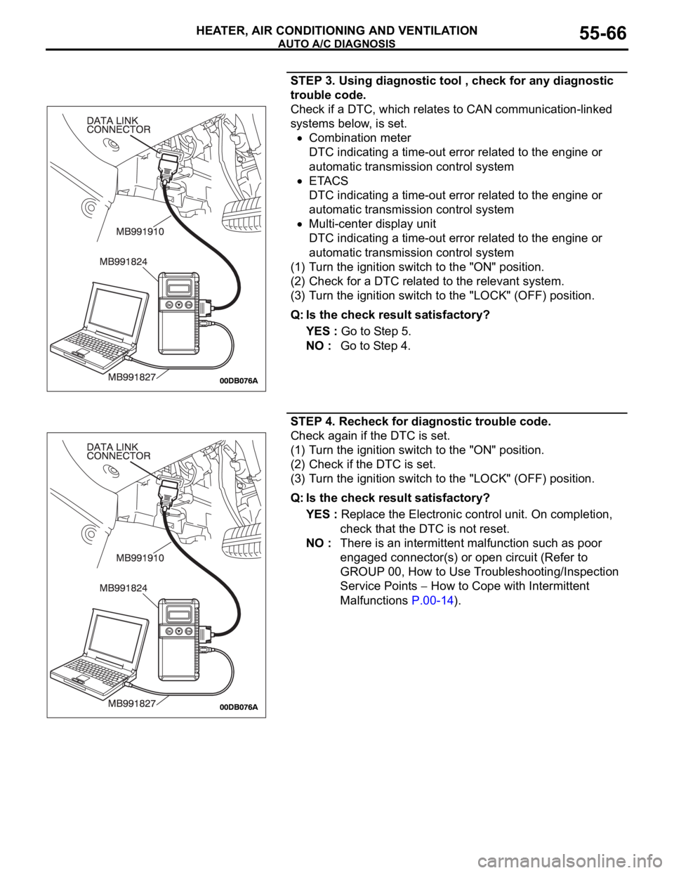
STEP 3. Using diagnostic tool , check for any diagnostic
trouble code.
Check if a DTC, which relates to CAN communication-linked
systems below, is set.
Combination meter
DTC indicating a time-out error related to the engine or
automatic transmission control system
ETACS
DTC indicating a time-out error related to the engine or
automatic transmission control system
Multi-center display unit
DTC indicating a time-out error related to the engine or
automatic transmission control system
(1) Turn the ignition switch to the "ON" position.
(2) Check for a DTC related to the relevant system.
(3) Turn the ignition switch to the "LOCK" (OFF) position.
Q: Is the check result satisfactory?
YES : Go to Step 5.
NO : Go to Step 4.
STEP 4. Recheck for diagnostic trouble code.
Check again if the DTC is set.
(1) Turn the ignition switch to the "ON" position.
(2) Check if the DTC is set.
(3) Turn the ignition switch to the "LOCK" (OFF) position.
Q: Is the check result satisfactory?
YES : Replace the Electronic control unit. On completion,
check that the DTC is not reset.
NO : There is an intermittent malfunction such as poor
engaged connector(s) or open circuit (Refer to
GROUP 00, How to Use Troubleshooting/Inspection
Service Points
How to Cope with Intermittent
Malfunctions P.00-14).
Page 1134 of 1500

KEYLESS ENTRY SYSTEM
BODY42-67
KEYLESS ENTRY SYSTEM
GENERAL DESCRIPTIONBGBJABIE
Antenna and receiver are incorporated in the
ETACS-ECU.
ID code can be registered by using Diagnostic
tool (MUT-III).
Transmitter is a key holder type, which incorpo-
rates lock button, unlock button, trunk button and
panic button
When the transmitter unlock button is pressed
once, the driver's door will be unlocked. If the but-
ton is pressed twice, all the doors will be
unlocked. The adjustment function also allows
you to open all the doors by pressing the unlock
button only once. For further details on using the
multi-center display to adjust the unlock opera-
tion, refer to GROUP 54B, On-vehicle Service
P.54B-486.
When the transmitter is operated, the answer-
back function will work as follows:
The answerback operation can be altered as fol-
lows:NOTE: Enabling/disabling the hazard warning
light flashing, the horn sounding in accordance
with the answerback function. For further details
on using the transmitter to adjust answerback,
P.42-72 see the section below. For further details
on using the multi-center display to adjust
answerback, refer to GROUP 54B, On-vehicle
Service P.54B-486. ITEM OPERATION
DOORS LOCKED DOORS UNLOCKED
Dome light Flashes once Illuminates for 15 seconds
Turn-signal lights (RH and LH) Flashes once Flashes twice
Horn Sounds once when the lock button
is pressed with all the doors locked-
ITEM ADJUSTMENT ITEM ADJUSTMENT DETAIL
Keyless entry system
confirmation by turn
signal lightsAdjustment of hazard answerback
when the transmitter is used to
lock doorsWhen adjusting hazard answerback after the
doors are locked with the transmitter, the
following flashing conditions can be selected.
a. Flash (default)
b. No flash
Adjustment of hazard answerback
when the transmitter is used to
unlock doorsWhen adjusting hazard answerback after the
doors are unlocked with the transmitter, the
following flashing conditions can be selected.
a. Flash (default)
b. No flash
Keyless entry system
confirmation by hornAdjustment of horn answerback
when the transmitter is used to
lock doorsWhen adjusting horn answerback after the
doors are locked with the transmitter, the
following horn conditions can be selected.
a. Horn sounds
b. Horn sounds if doors are already locked
(default)
c. Horn does not sound
Page 1135 of 1500
KEYLESS ENTRY SYSTEM
BODY42-68
If none of the doors is opened or the ignition key
is not inserted in the ignition switch within 30 sec-
onds after the doors are unlocked using the
transmitter, the ETACS-ECU will relock the doors
automatically. This is called "Timer lock function."
This timer lock function prevents accidental
unlocking of doors. The adjustment function
allows you to change the timer lock period from 30 seconds (default setting) to 60, 120 or 180
seconds. For further details on using the
multi-center display (middle grade type) to adjust
the timer lock period, refer to GROUP 54B,
On-vehicle Service P.54B-486.
NOTE: The timer lock period begins when the doors
are unlocked, and ends when the doors is relocked
automatically.
KEYLESS ENTRY SYSTEM DIAGNOSISBGBCJGAI
The keyless entry system is controlled by the Simpli-
fied Wiring System (SWS). Refer to GROUP 54B,
SWS Diagnosis P.54B-57.
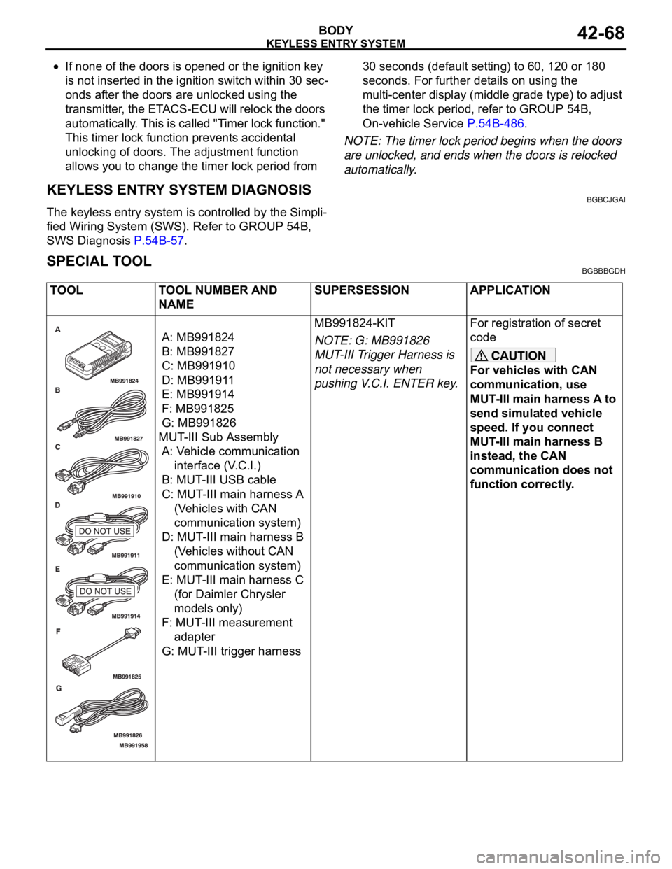
SPECIAL TOOLBGBBBGDH
TOOL TOOL NUMBER AND
NAMESUPERSESSION APPLICATION
A: MB991824
B: MB991827
C: MB991910
D: MB991911
E: MB991914
F: MB991825
G: MB991826
MUT-III Sub Assembly
A: Vehicle communication
interface (V.C.I.)
B: MUT-III USB cable
C: MUT-III main harness A
(Vehicles with CAN
communication system)
D: MUT-III main harness B
(Vehicles without CAN
communication system)
E: MUT-III main harness C
(for Daimler Chrysler
models only)
F: MUT-III measurement
adapter
G: MUT-III trigger harnessMB991824-KIT
NOTE: G: MB991826
MUT-III Trigger Harness is
not necessary when
pushing V.C.I. ENTER key.For registration of secret
code
For vehicles with CAN
communication, use
MUT-III main harness A to
send simulated vehicle
speed. If you connect
MUT-III main harness B
instead, the CAN
communication does not
function correctly.
Page 1291 of 1500
TRACTION CONTROL SYSTEM (TCL) DIAGNOSIS
TRACTION CONTROL SYSTEM (TCL)13C-12
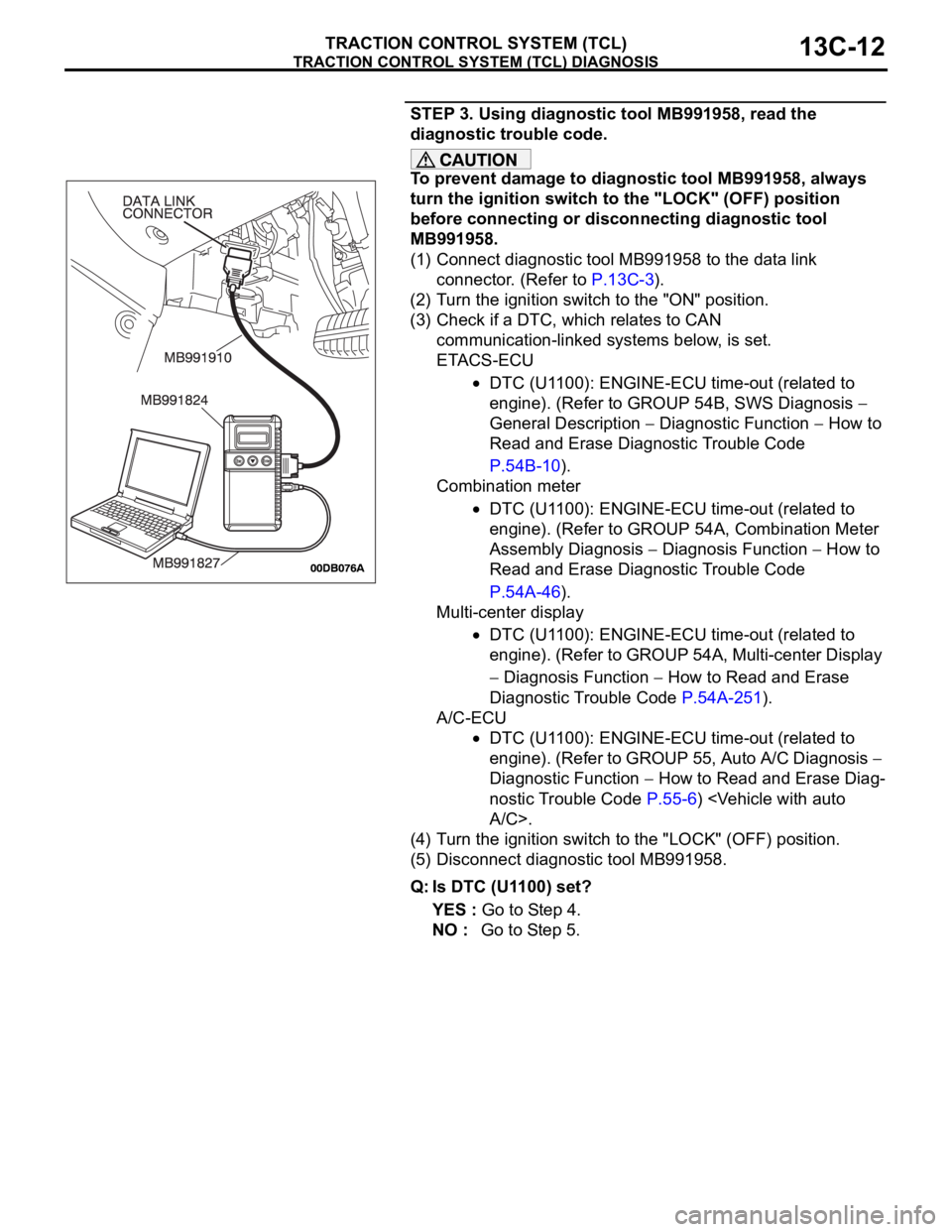
STEP 3. Using diagnostic tool MB991958, read the
diagnostic trouble code.
To prevent damage to diagnostic tool MB991958, always
turn the ignition switch to the "LOCK" (OFF) position
before connecting or disconnecting diagnostic tool
MB991958.
(1) Connect diagnostic tool MB991958 to the data link
connector. (Refer to P.13C-3).
(2) Turn the ignition switch to the "ON" position.
(3) Check if a DTC, which relates to CAN
communication-linked systems below, is set.
ETACS-ECU
DTC (U1100): ENGINE-ECU time-out (related to
engine). (Refer to GROUP 54B, SWS Diagnosis
General Description
Diagnostic Function How to
Read and Erase Diagnostic Trouble Code
P.54B-10).
Combination meter
DTC (U1100): ENGINE-ECU time-out (related to
engine). (Refer to GROUP 54A, Combination Meter
Assembly Diagnosis
Diagnosis Function How to
Read and Erase Diagnostic Trouble Code
P.54A-46).
Multi-center display
DTC (U1100): ENGINE-ECU time-out (related to
engine). (Refer to GROUP 54A, Multi-center Display
Diagnosis Function How to Read and Erase
Diagnostic Trouble Code P.54A-251).
A/C-ECU
DTC (U1100): ENGINE-ECU time-out (related to
engine). (Refer to GROUP 55, Auto A/C Diagnosis
Diagnostic Function
How to Read and Erase Diag-
nostic Trouble Code P.55-6)
(4) Turn the ignition switch to the "LOCK" (OFF) position.
(5) Disconnect diagnostic tool MB991958.
Q: Is DTC (U1100) set?
YES : Go to Step 4.
NO : Go to Step 5.
Page 1295 of 1500
TRACTION CONTROL SYSTEM (TCL) DIAGNOSIS
TRACTION CONTROL SYSTEM (TCL)13C-16
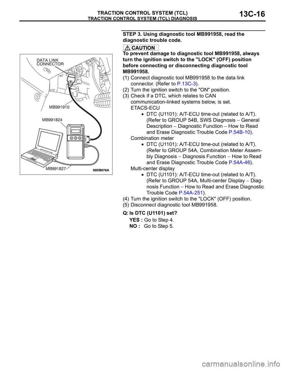
STEP 3. Using diagnostic tool MB991958, read the
diagnostic trouble code.
To prevent damage to diagnostic tool MB991958, always
turn the ignition switch to the "LOCK" (OFF) position
before connecting or disconnecting diagnostic tool
MB991958.
(1) Connect diagnostic tool MB991958 to the data link
connector. (Refer to P.13C-3).
(2) Turn the ignition switch to the "ON" position.
(3) Check if a DTC, which relates to CAN
communication-linked systems below, is set.
ETACS-ECU
DTC (U1101): A/T-ECU time-out (related to A/T).
(Refer to GROUP 54B, SWS Diagnosis
General
Description
Diagnostic Function How to Read
and Erase Diagnostic Trouble Code P.54B-10).
Combination meter
DTC (U1101): A/T-ECU time-out (related to A/T).
(Refer to GROUP 54A, Combination Meter Assem-
bly Diagnosis
Diagnosis Function How to Read
and Erase Diagnostic Trouble Code P.54A-46).
Multi-center display
DTC (U1101): A/T-ECU time-out (related to A/T).
(Refer to GROUP 54A, Multi-center Display
Diag-
nosis Function
How to Read and Erase Diagnostic
Trouble Code P.54A-251).
(4) Turn the ignition switch to the "LOCK" (OFF) position.
(5) Disconnect diagnostic tool MB991958.
Q: Is DTC (U1101) set?
YES : Go to Step 4.
NO : Go to Step 5.