trunk release MITSUBISHI 380 2005 Workshop Manual
[x] Cancel search | Manufacturer: MITSUBISHI, Model Year: 2005, Model line: 380, Model: MITSUBISHI 380 2005Pages: 1500, PDF Size: 47.87 MB
Page 876 of 1500
DUCTS
HEATER, AIR CONDITIONING AND VENTILATION55-175
DUCTS
REMOVAL AND INSTALLATIONM1553001000275
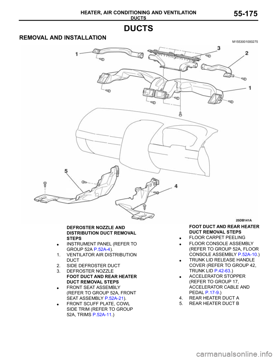
DEFROSTER NOZZLE AND
DISTRIBUTION DUCT REMOVAL
STEPS
INSTRUMENT PANEL (REFER TO
GROUP 52A P.52A-4).
1. VENTILATOR AIR DISTRIBUTION
DUCT
2. SIDE DEFROSTER DUCT
3. DEFROSTER NOZZLE
FOOT DUCT AND REAR HEATER
DUCT REMOVAL STEPS
FRONT SEAT ASSEMBLY
(REFER TO GROUP 52A, FRONT
SEAT ASSEMBLY P.52A-21).
FRONT SCUFF PLATE, COWL
SIDE TRIM (REFER TO GROUP
52A, TRIMS P.52A-11.)
FLOOR CARPET PEELING
FLOOR CONSOLE ASSEMBLY
(REFER TO GROUP 52A, FLOOR
CONSOLE ASSEMBLY P.52A-10.)
TRUNK LID RELEASE HANDLE
COVER (REFER TO GROUP 42,
TRUNK LID P.42-63.)
ACCELERATOR STOPPER
(REFER TO GROUP 17,
ACCELERATOR CABLE AND
PEDAL P.17-9.)
4. REAR HEATER DUCT A
5. REAR HEATER DUCT BFOOT DUCT AND REAR HEATER
DUCT REMOVAL STEPS
Page 1026 of 1500
CROSSMEMBER
POWER PLANT MOUNT32-9
CROSSMEMBER
REMOVAL AND INSTALLATIONM1321003200551
Before removing the steering wheel and air bag module assembly, always refer to GROUP 52B -
Service Precautions (P.52B-16), Air bag Module and Clock Spring (P.52B-237). Also, set the front
wheels so that they are facing straight forward, and remove the ignition key. If you fail to do this,
the SRS clock spring will be damaged, causing the SRS air bag to be inoperative and serious
injury.
*1: Indicates parts which should be initially tightened, and then fully tightened after placing the
vehicle horizontally and loading the full weight of the engine on the vehicle body.
*2: Indicates parts which should be temporarily tightened, and then fully tightened with the vehicle
on the ground in the unladen condition.
Pre-removal Operation
Power Steering Fluid Draining (Refer to GROUP 37,
On-vehicle Service Fluid Replacement P.37-18).
Power Steering Hoses Removal and Installation (Refer to
GROUP 37, Power Steering Hoses P.37A-57).
Air Bag Module and Steering Wheel Assembly Removal
(Refer to GROUP 37, Steering Wheel P.37-23).
Clock Spring Removal (Refer to GROUP 52B, Air Bag
Module and Clock Spring P.52B-237).
Floor Console Assembly Removal (Refer to GROUP 52A,
Floor Console Assembly P.52A-10).
Front Scuff Plate (LH) and Cowl Side Trim (LH) Removal
(Refer to GROUP 52A, Trims P.52A-11).
Trunk Lid Release Handle Cover Removal (Refer to
GROUP 42, Trunk Lid P.42-63).
Accelerator Stopper Removal (Refer to GROUP 17,
Accelerator Pedal P.17-9).
Front Floor Carpet Removal
Centremember Removal (Refer to P.32-7).Post-installation Operation
Centremember Installation (Refer to P.32-7).
Front Floor Carpet Installation
Accelerator Stopper Installation (Refer to GROUP 17,
Accelerator Pedal P.17-9).
Trunk Lid Release Handle Cover Installation (Refer to
GROUP 42, Trunk Lid P.42-63).
Front Scuff Plate (LH) and Cowl Side Trim (LH) Installa-
tion (Refer to GROUP 52A, Trims P.52A-11).
Floor Console Assembly Installation (Refer to GROUP
52A, Floor Console Assembly P.52A-10).
Clock Spring Installation (Refer to GROUP 52B, Air Bag
Module and Clock Spring P.52B-237).
Steering Wheel Assembly and Air Bag Module Installation
(Refer to P.37-23).
Check the dust cover for cracks or damage by pushing it
with your finger.
Power Steering Fluid Supplying (Refer to GROUP 37,
On-vehicle Service Fluid Replacement P.37-18).
Power Steering Fluid Line Bleeding (Refer to P.37-18).
Checking Steering Wheel Position with Wheels Straight
Ahead.
Front Wheel Alignment Adjustment (Refer to GROUP 33,
On-vehicle Service
Front Wheel Alignment Check and
Adjustment P.33-6).
Page 1128 of 1500
TRUNK LID
BODY42-61
STEP 2. Retest the system.
Q: Are the clearances between the body panels even?
YES :
The procedure is complete.
NO : Return to Step 1.
INSPECTION PROCEDURE 3: Uneven Height
DIAGNOSIS
STEP 1. Check the trunk lid bumper height.
Q: Is the trunk lid bumper height proper?
YES :
Then go to Step 2.
NO : Adjust the trunk lid bumper. Refer to
P.42-62.
STEP 2. Retest the system.
Q: Are the trunk lid and body height even?
YES :
The procedure is complete.
NO : Return to Step 1.
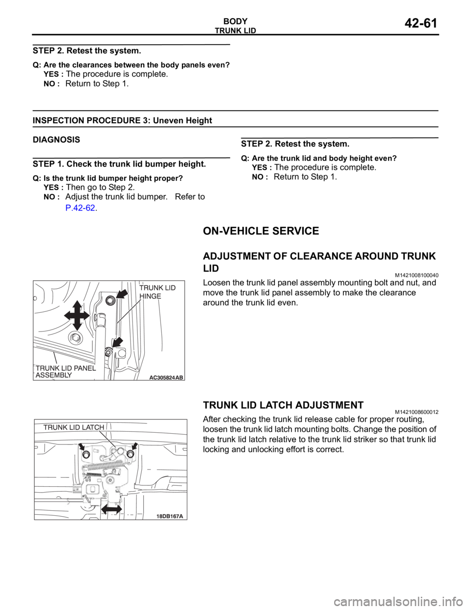
ON-VEHICLE SERVICE
ADJUSTMENT OF CLEARANCE AROUND TRUNK
LID
M1421008100040
Loosen the trunk lid panel assembly mounting bolt and nut, and
move the trunk lid panel assembly to make the clearance
around the trunk lid even.
TRUNK LID LATCH ADJUSTMENTM1421008600012
After checking the trunk lid release cable for proper routing,
loosen the trunk lid latch mounting bolts. Change the position of
the trunk lid latch relative to the trunk lid striker so that trunk lid
locking and unlocking effort is correct.
Page 1130 of 1500
TRUNK LID
BODY42-63
TRUNK LID
REMOVAL AND INSTALLATIONM1421002200191
Do not disassemble or throw the trunk lid gas spring into fire.
Punch a hole in the trunk lid gas spring before disposal to release the gas inside.
Ensure the trunk lid gas spring piston rod does not come into contact with foreign material.
Post-installation Operation
Adjustment of Clearance Around Trunk Lid (Refer to
P.42-61).
Trunk Lid Latch Adjustment (Refer to P.42-61).
Trunk Lid Height Adjustment (Refer to P.42-62).
Page 1131 of 1500
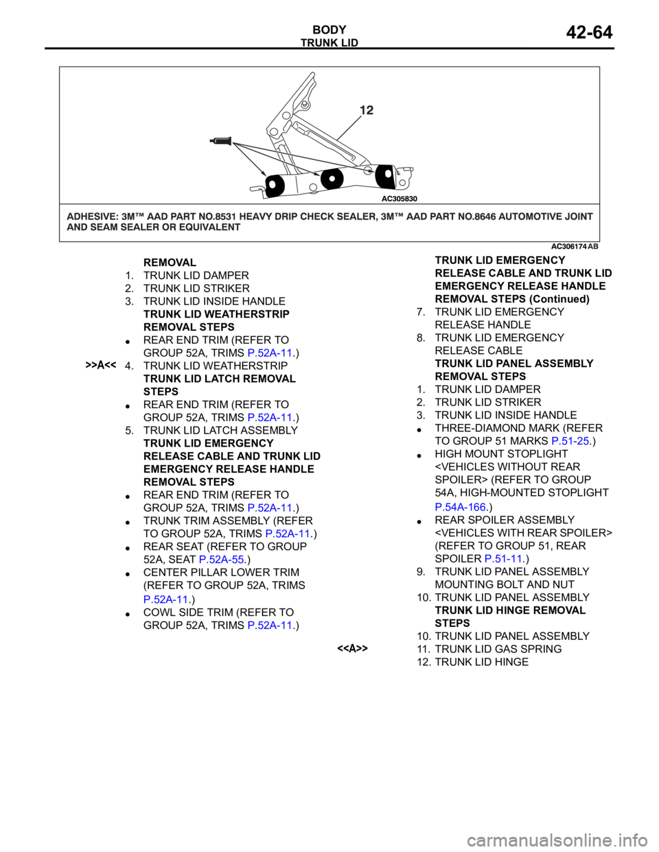
TRUNK LID
BODY42-64
REMOVAL
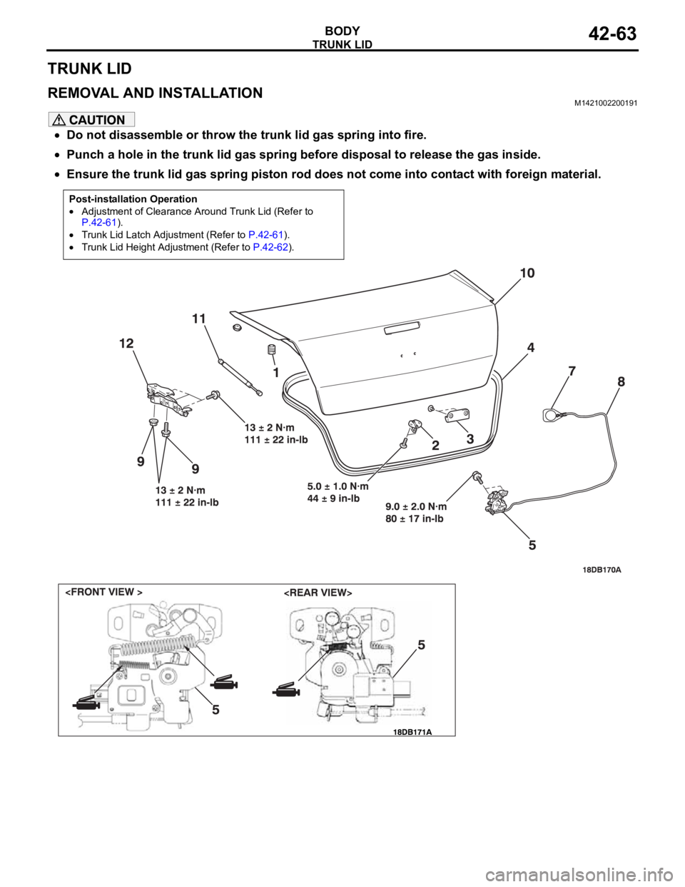
1. TRUNK LID DAMPER
2. TRUNK LID STRIKER
3. TRUNK LID INSIDE HANDLE
TRUNK LID WEATHERSTRIP
REMOVAL STEPS
REAR END TRIM (REFER TO
GROUP 52A, TRIMS P.52A-11.)
>>A<<4. TRUNK LID WEATHERSTRIP
TRUNK LID LATCH REMOVAL
STEPS
REAR END TRIM (REFER TO
GROUP 52A, TRIMS P.52A-11.)
5. TRUNK LID LATCH ASSEMBLY
TRUNK LID EMERGENCY
RELEASE CABLE AND TRUNK LID
EMERGENCY RELEASE HANDLE
REMOVAL STEPS
REAR END TRIM (REFER TO
GROUP 52A, TRIMS P.52A-11.)
TRUNK TRIM ASSEMBLY (REFER
TO GROUP 52A, TRIMS P.52A-11.)
REAR SEAT (REFER TO GROUP
52A, SEAT P.52A-55.)
CENTER PILLAR LOWER TRIM
(REFER TO GROUP 52A, TRIMS
P.52A-11.)
COWL SIDE TRIM (REFER TO
GROUP 52A, TRIMS P.52A-11.)7. TRUNK LID EMERGENCY
RELEASE HANDLE
8. TRUNK LID EMERGENCY
RELEASE CABLE
TRUNK LID PANEL ASSEMBLY
REMOVAL STEPS
1. TRUNK LID DAMPER
2. TRUNK LID STRIKER
3. TRUNK LID INSIDE HANDLE
THREE-DIAMOND MARK (REFER
TO GROUP 51 MARKS P.51-25.)
HIGH MOUNT STOPLIGHT
54A, HIGH-MOUNTED STOPLIGHT
P.54A-166.)
REAR SPOILER ASSEMBLY
(REFER TO GROUP 51, REAR
SPOILER P.51-11.)
9. TRUNK LID PANEL ASSEMBLY
MOUNTING BOLT AND NUT
10. TRUNK LID PANEL ASSEMBLY
TRUNK LID HINGE REMOVAL
STEPS
10. TRUNK LID PANEL ASSEMBLY
<>11. TRUNK LID GAS SPRING
12. TRUNK LID HINGETRUNK LID EMERGENCY
RELEASE CABLE AND TRUNK LID
EMERGENCY RELEASE HANDLE
REMOVAL STEPS (Continued)