ESP MITSUBISHI ASX 2017 Owner's Manual (in English)
[x] Cancel search | Manufacturer: MITSUBISHI, Model Year: 2017, Model line: ASX, Model: MITSUBISHI ASX 2017Pages: 458, PDF Size: 22.98 MB
Page 2 of 458
Foreword
E09200106591
Thank you for selecting an ASX as your new vehicle.
This owner’s
manual will add to your understanding and full enjoyment of
the many fine features of this vehicle.
It contains information prepared to acquaint you with the proper way to oper-
ate and maintain your vehicle for the utmost in driving pleasure.
MITSUBISHI MOTORS Europe B.V. reserves the right to make changes in
design and specifications and/or to make additions to or improvements in
this product without obligation to install them on products previously manu- factured.
It is an absolute requirement for the driver to strictly observe all laws and
regulations concerning vehicles.
This owner’s manual has been written in compliance with such laws and reg-
ulations, but some of the contents may become contradictory with later amendment of the laws and regulations.
Please leave this owner’s manual in this vehicle at time of resale. The next
owner will appreciate having access to the information contained in this
owner’s manual.
Repairs to your vehicle:
Vehicles in the warranty period:
All warranty repairs must be carried out by a MITSUBISHI MOTORS Au- thorized Service Point.
Vehicles outside the warranty period:
Where the vehicle is repaired is at the discretion of the owner. Throughout this owner’s manual the words
WARNING and CAUTION
appear.
These
serve as reminders to be especially careful. Failure to follow instruc-
tions could result in personal injury or damage to your vehicle. WARNING
indicates a strong possibility of severe personal injury or death if in- structions are not followed. CAUTION
means hazards or unsafe practices that could cause minor personal in-
jury or damage to your vehicle.
You will see another important symbol: NOTE: gives helpful information.
*: indicates optional equipment.It may
differ according to the sales classification; refer
to the sales catalogue.
Abbreviations used in this owner’s manual:
LHD: Left-Hand Drive
RHD: Right-Hand Drive
M/T : Manual Transmission
A/T: Automatic Transmission
CVT: Continuously Variable Transmission
The symbol used on the vehicles: : See owner’s manual Information for station service
E09300104149 Fuel Capacity
Petrol-powered vehicles 2WD models
58 litres
*1
63 litres *2
4WD models 60 litres
Diesel-powered vehicles 60 litres Fuel requirements
Petrol-powered vehicles
Unleaded petrol octane number (EN228)1600 models, 1800 models: 95 RON or higher
2000 models: 90 RON or higher
Diesel-powered vehicles Cetane number (EN590): 51 or higher
Refer to the “General information” section for the fuel selection. Engine oil
Refer to the “Maintenance” section for the selection of engine oil. Tyre inflation pressure
Refer to the “Maintenance” section for the tyre inflation pressure.
*1 : For vehicles with vehicle identification numbers that begin with “4”
*2 : For vehicles with vehicle identification numbers that begin with “J” CAUTION
l Diesel-powered vehicles are designed to use only diesel fuel that meets the EN 590 standard.
Use of any other type of diesel fuel can adversely affect the engine. NOTE
l
For the location of the vehicle identification number, refer to “Vehicle identification number” on page 11-02. © 2016 Mitsubishi Motors Corporation
17 OGAE17E2
BLO-16-000906
Page 21 of 458
CAUTIONlYour vehicle is equipped with a diagnosis
connector for checking and servicing theelectronic control system.
Do not connect a device other than a diagno-
sis tool for inspections and service to this
connector. Otherwise, the battery could be discharged, the electronic devices of the ve- hicle could malfunction, or other unexpected
problems could result.
In addition, malfunctions caused by connect-
ing a device other than a diagnosis tool may not be covered under warranty.
l The installation of accessories, optional
parts, etc., should only be carried out
within the limits prescribed by law in your country, and in accordance with the
guidelines and warnings contained with-
in the documents accompanying this ve- hicle.
l Installing electric components incorrect-
ly could lead to a fire. See the “Modifi- cation/ alterations to the electrical or fuel
systems” section within this owner’s
manual.
l When installing the radio, for the re-
quired information (frequency, transmis-
sion output, installing procedure), con-
sult a MITSUBISHI MOTORS Author-
ized Service Point.
If the frequency, transmission output and
installing condition are not appropriate, it can adversely affect the electronic de-vices and could lead to unsafe vehicle
operation.
l Using a cellular phone or radio set inside
the vehicle without an external antenna
may cause electrical system interference,
which could lead to unsafe vehicle oper- ation.
l Tyres and wheels which do not meet
specifications must not be used.
Refer to the “Specifications” section for information regarding wheel and tyre
sizes.
Important points!
Due to large number of accessory and re- placement parts of different manufactures
available in the market, it is not possible, not
only for MITSUBISHI MOTORS , but also
for a MITSUBISHI MOTORS Authorized
Service Point, to check whether the attach- ment or installation of such parts affects theoverall safety of your MITSUBISHI-vehicle.
Even when such parts are officially author-
ized, for example by a “general operators permit” (an appraisal for the part) or throughthe execution of the part in an officially ap-
proved manner of construction, or when a single operation permit following the attach-
ment or installation of such parts, it cannot be deduced from that alone, that the driving
safety of your vehicle has not been affected.
Consider also that there basically exists no li- ability on the part of the appraiser or the offi- cial. Maximum safety can only be ensured
with parts recommended, sold and fitted or
installed by a MITSUBISHI MOTORS Au-
thorized Service Point ( MITSUBISHI
MOTORS genuine replacement parts and
MITSUBISHI MOTORS accessories). The
same also pertains to modifications of
MITSUBISHI vehicles with respect to the
production specifications. For safety reasons, do not attempt any modifications other than
those that follow the recommendations of a MITSUBISHI MOTORS Authorized Service
Point.
Installation of accessories
2-05OGAE17E2General information2
Page 30 of 458
NOTElThe outside rear-view mirrors cannot be fol-
ded or extended using the remote control
switch in the following conditions:
• The key is left in the ignition switch.
• A door or the tailgate is open or ajar.
l The remote control switch will operate with-
in approximately 4 m from the vehicle.
However, the operating range of the remote control switch may change if the vehicle is located near a power station, or radio/TV
broadcasting station.
l If either of the following problems occurs,
the battery may be exhausted.
• The remote control switch is operated at
the correct distance from the vehicle, but
the doors and tailgate are not locked/ unlocked in response.
• The indication lamp (3) is dim or does not
come on.
For further information, please contact your MITSUBISHI MOTORS Authorized
Service Point.
If you replace the battery yourself, refer to
“Procedure for replacing the remote con-
trol switch battery” on page 3-06.
l If your remote control switch is lost or dam-
aged, please contact your MITSUBISHI
MOTORS Authorized Service Point for a re-
placement remote control switch.NOTEl If you wish to add a remote control switch,
we recommend you to contact a
MITSUBISHI MOTORS Authorized Serv-
ice Point.
A maximum of 8 remote control switches
are available for your vehicle.Setting of door and tailgate un-
lock function (Except for vehi- cles equipped with a Dead
Lock System)
E00310300257
The door and tailgate unlock function can be set to the following two conditions.
Each time the door and tailgate unlock func-
tion is set, a chime will sound to tell you the
condition of the door and tailgate unlock function.
Number of
chimesConditionOne chimeAll doors and the tailgate un-lockTwo chimesDriver’s door unlock only
1. Remove the key from the ignition
switch.
2. Place the combination headlamps and
dipper switch in the “OFF” position, and leave the driver’s door open.
3. Press and hold the LOCK switch (1) for
4 to 10 seconds and then also press the
UNLOCK switch (2) during this time.
4. Release in sequence the LOCK and UN-
LOCK switches within 10 seconds of pressing the LOCK switch in step 3.Procedure for replacing the re-
mote control switch battery
E00309501692
Before replacing the battery, remove static electricity from your body by touching a met-
al part such as doorknob of the room.
WARNINGl Danger of explosion if battery is incor-
rectly replaced.
Replace only with the same battery or an
equivalent type.CAUTIONl When the remote control switch case is
opened, be careful to keep water, dust, etc. out. Also, do not touch the internal compo-
nents.NOTEl You may purchase a replacement battery at
an electric appliance store.
Keyless entry system*
3-06OGAE17E2Locking and unlocking3
Page 47 of 458
Operation of the outside rear-view mirrors (Vehicles equip- ped with mirror retractorswitch)
E00311200325
To fold
Within 30 seconds of locking the doors and tailgate using the LOCK switch (1), press the LOCK switch twice rapidly to fold the out-
side rear-view mirrors.
To extend
Within 30 seconds of unlocking the doors
and tailgate using the UNLOCK switch (2),
press the UNLOCK switch twice rapidly to return the outside rear-view mirrors to their
extended positions.
The outside rear-view mirrors are not ini-
tially set to work as described above. If you want them to work as described above, youneed to set them so that they do not retract/
extend when the doors and tailgate are
locked/unlocked using the keyless entry sys-
tem or keyless operation system.
Refer to “Starting and driving: Outside rear-
view mirrors” on page 6-10.
For details, please consult a MITSUBISHI
MOTORS Authorized Service Point.NOTEl The outside rear-view mirrors cannot be fol-
ded or extended using the remote control
switch when one of the doors or the tailgate
is open or ajar.
l For vehicles equipped with the mirror retrac-
tor switch, the outside rear-view mirrors au- tomatically retract or extend when all the
doors and tailgate are locked or unlocked us- ing the remote control switches of the key- less entry system.
Refer to “Starting and driving: Outside rear- view mirrors” on page 6-10.
l The remote control switch will operate with-
in approximately 4 m from the vehicle. However, the operating range of the remote
control switch may change if the vehicle is located near a power station, or radio/TVbroadcasting station.
l If either of the following problems occurs,
the battery may be exhausted.
• The remote control switch is operated at
the correct distance from the vehicle, but
the doors and tailgate are not locked/
unlocked in response.
• The indication lamp (3) is dim or does not
come on.
For further information, please contact your MITSUBISHI MOTORS Authorized
Service Point.
If you replace the battery yourself, refer to
“Procedure for replacing the remote con- trol switch battery” on page 3-24.NOTEl If your remote control switch is lost or dam-
aged, please contact your MITSUBISHI
MOTORS Authorized Service Point for a re-
placement remote control switch.
l If you wish to add a remote control switch,
please contact your MITSUBISHI
MOTORS Authorized Service Point. A max-
imum of 4 remote control switches are avail- able for your vehicle.Setting of door and tailgate un-
lock function (Except for vehi- cles equipped with a Dead LockSystem)
E00310400304
The door and tailgate unlock function can be set to the following two conditions.
Each time the door and tailgate unlock func-
tion is set, a chime will sound to tell you the
condition of the door and tailgate unlock function.
Number of
chimesConditionOne chimeAll doors and the tailgate un-lockTwo chimesDriver’s door unlock only
1. Put the operation mode in OFF.
Keyless operation system*
3-23OGAE17E2Locking and unlocking3
Page 63 of 458
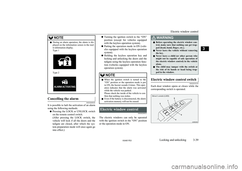
NOTElDuring an alarm operation, the alarm is dis-
played on the information screen in the mul-
ti-information display.
Type 1
Type 2
Cancelling the alarm
E00302000428
It is possible to halt the activation of an alarm
using the following methods:
l Pressing the LOCK or UNLOCK switch
on the remote control switch.
(After pressing the LOCK switch, the vehicle will lock if all the doors and the
tailgate are closed, after which the sys- tem preparation mode will once again go
into effect.)
l Turning the ignition switch to the “ON”
position (except for vehicles equipped
with the keyless operation system).
l Putting the operation mode in ON (vehi-
cles equipped with the keyless operation
system).
l Holding the keyless operation key and
locking and unlocking the doors and the
tailgate using the keyless operation func- tion (vehicles equipped with the keylessoperation system).NOTEl When the ignition switch is turned to the
“ON” position or the operation mode is put in ON, the buzzer sounds 4 times. This oper-
ation indicates that the alarm was activated while the vehicle was parked.
Please check the inside of the vehicle to con-
firm that nothing was stolen.
l Even if the battery is disconnected, the alarm
activation memory will not be erased.Electric window control
E00302200521
The electric windows can only be operatedwith the ignition switch in the “ON” position
or the operation mode in ON.
WARNINGl Before operating the electric window con-
trol, make sure that nothing can get trap-
ped (head, hand, finger, etc.).
l Never leave the vehicle without removing
the key.
l Never leave a child (or other person who
might not be capable of safe operation of
the electric window control) in the vehicle alone.
l The child may tamper with the switch at
the risk of its hands or head being trap- ped in the window.Electric window control switch
E00302301558
Each door window opens or closes while the
corresponding switch is operated.
Driver’s switch (LHD)
Electric window control
3-39OGAE17E2Locking and unlocking3
Page 64 of 458
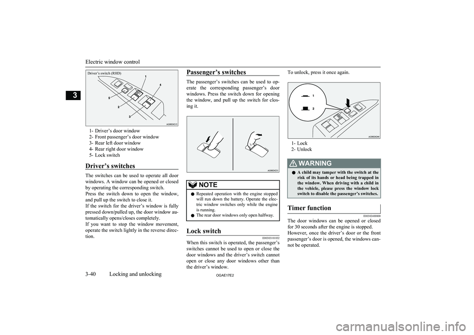
Driver’s switch (RHD)
1- Driver’s door window
2- Front passenger’s door window
3- Rear left door window
4- Rear right door window
5- Lock switch
Driver’s switches
The switches can be used to operate all door
windows. A window can be opened or closed by operating the corresponding switch.Press the switch down to open the window, and pull up the switch to close it.
If the switch for the driver’s window is fully
pressed down/pulled up, the door window au-
tomatically opens/closes completely.
If you want to stop the window movement,
operate the switch lightly in the reverse direc-
tion.
Passenger’s switches
The passenger’s switches can be used to op-
erate the corresponding passenger’s door
windows. Press the switch down for opening the window, and pull up the switch for clos-
ing it.
NOTEl Repeated operation with the engine stopped
will run down the battery. Operate the elec-
tric window switches only while the engine is running.
l The rear door windows only open halfway.Lock switch
E00303101032
When this switch is operated, the passenger’s
switches cannot be used to open or close the door windows and the driver’s switch cannot
open or close any door windows other than
the driver’s window.
To unlock, press it once again.
1- Lock
2- Unlock
WARNINGl A child may tamper with the switch at the
risk of its hands or head being trapped in the window. When driving with a child in
the vehicle, please press the window lock switch to disable the passenger’s switches.Timer function
E00302400800
The door windows can be opened or closed
for 30 seconds after the engine is stopped.
However, once the driver’s door or the front passenger’s door is opened, the windows can-
not be operated.
Electric window control
3-40OGAE17E2Locking and unlocking3
Page 65 of 458
Safety mechanism (driver’sdoor window only)
E00302501895
If a hand or head is trapped in the closing
window, it will lower automatically.
Nonetheless, make sure that nobody puts
their head or hand out of the window when closing the driver’s door window.
The lowered window will become operation-
al after a few seconds.
WARNINGl If the battery terminals are disconnected
or the fuse for electric window is replaced,
the safety mechanism will be cancelled.
If a hand or head got trapped, a serious injury could result.CAUTIONl The safety mechanism is cancelled just be-
fore the window is fully closed. This allows the window to close completely. Therefore be especially careful that no fingers are trap-
ped in the window.
l The safety mechanism is deactivated while
the switch is pulled up. Therefore be espe-
cially careful that fingers are not trapped in the door window opening.NOTEl The safety mechanism can be activated if the
driving conditions or other circumstancescause the driver’s door window to be subjec- ted to a physical shock similar to that caused
by a trapped hand or head.
l If the battery terminals are disconnected or
the fuse for electric window is replaced, the
safety mechanism will be cancelled and the door window will not automatically open/ close completely.
If the window is open, repeatedly raise the
driver’s door window switch until the win-
dow has been fully closed.
Following this, release the switch, raise the switch once again and hold it in this condi- tion for at least 1 second, then release it.
You should now be able to operate the driv- er’s door window in the normal fashion.Sunshade*
E00302800279WARNINGlNever leave a child (or other person who
might not be capable of safe operation ofthe sunshade switch) in the vehicle alone.
l Before operating the sunshade, make sure
that nothing can be trapped (head, hand, finger, etc.).WARNINGl Do not bring your head, hand, finger, etc.
near the opening edge of the sunshade re-
ceptacle while the vehicle is in motion.
It may cause injury to your head, hand, finger, etc. in the event of sudden braking.CAUTIONl Do not place heavy luggage on the panoram-
ic glass roof. Doing so could damage the glass roof.
l Do not hang heavy luggage from, allow a
person to hang onto, or apply any other strong force to the opening of the sunshade receptacle or the parts between the ceiling
and the sunshade opening on either side. Do- ing so could damage the sunshade.NOTEl Release the switch as soon as the sunshade
reaches the fully open or fully closed posi-
tion.
l If the sunshade does not operate when the
sunshade switch is operated, release the
switch and check whether something is trap- ped by the sunshade. If nothing is trapped,
we recommend you to have the sunshade checked.
l Operating the sunshade repeatedly with the
engine stationary will run down the battery.
Operate the sunshade while the engine is running.
Sunshade*
3-41OGAE17E2Locking and unlocking3
Page 66 of 458
NOTElClose the sunshade when parking the vehicle
for a long time. Parking in the hot sun with
the sunshade open will make the vehicle in-
side extremely hot.
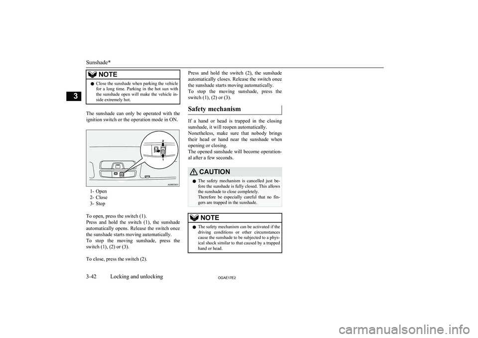
The sunshade can only be operated with the
ignition switch or the operation mode in ON.
1- Open
2- Close
3- Stop
To open, press the switch (1).
Press and hold the switch (1), the sunshade automatically opens. Release the switch once
the sunshade starts moving automatically.
To stop the moving sunshade, press the
switch (1), (2) or (3).
To close, press the switch (2).
Press and hold the switch (2), the sunshade
automatically closes. Release the switch once
the sunshade starts moving automatically.
To stop the moving sunshade, press the
switch (1), (2) or (3).
Safety mechanism
If a hand or head is trapped in the closingsunshade, it will reopen automatically.
Nonetheless, make sure that nobody brings
their head or hand near the sunshade when opening or closing.
The opened sunshade will become operation-
al after a few seconds.
CAUTIONl The safety mechanism is cancelled just be-
fore the sunshade is fully closed. This allows the sunshade to close completely.
Therefore be especially careful that no fin-
gers are trapped in the sunshade.NOTEl The safety mechanism can be activated if the
driving conditions or other circumstancescause the sunshade to be subjected to a phys-
ical shock similar to that caused by a trapped
hand or head.
Sunshade*
3-42OGAE17E2Locking and unlocking3
Page 74 of 458
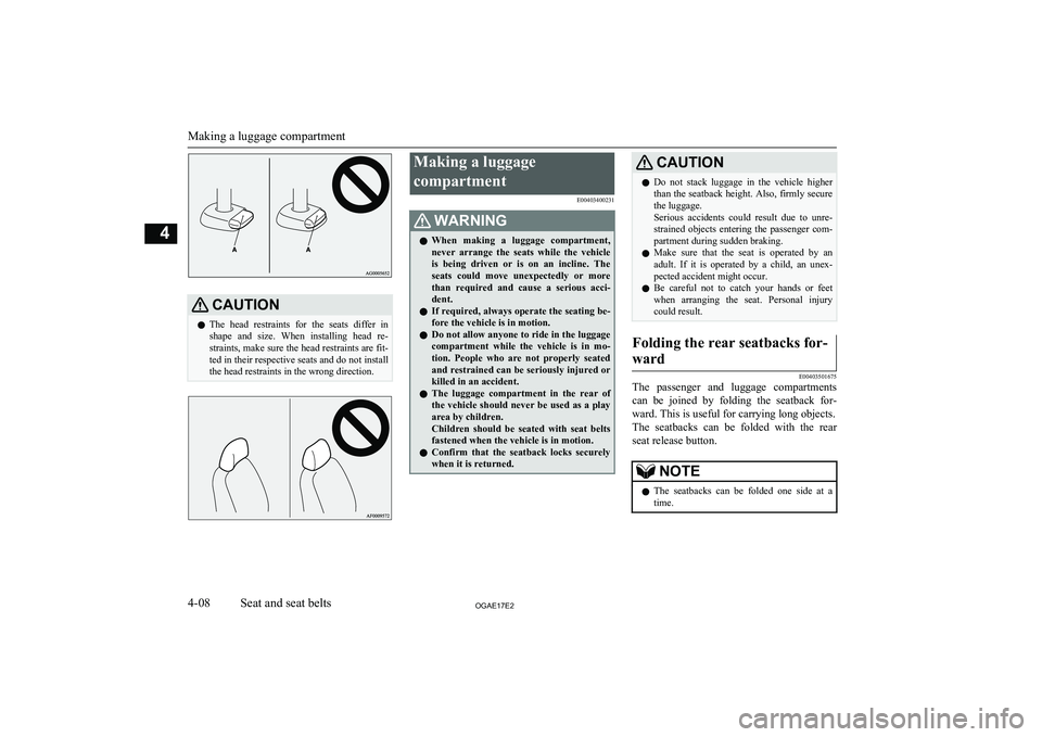
CAUTIONlThe head restraints for the seats differ in
shape and size. When installing head re- straints, make sure the head restraints are fit- ted in their respective seats and do not install
the head restraints in the wrong direction.Making a luggage
compartment E00403400231WARNINGlWhen making a luggage compartment,
never arrange the seats while the vehicle
is being driven or is on an incline. The seats could move unexpectedly or more
than required and cause a serious acci- dent.
l If required, always operate the seating be-
fore the vehicle is in motion.
l Do not allow anyone to ride in the luggage
compartment while the vehicle is in mo-
tion. People who are not properly seated
and restrained can be seriously injured or killed in an accident.
l The luggage compartment in the rear of
the vehicle should never be used as a play area by children.
Children should be seated with seat belts fastened when the vehicle is in motion.
l Confirm that the seatback locks securely
when it is returned.CAUTIONl Do not stack luggage in the vehicle higher
than the seatback height. Also, firmly securethe luggage.
Serious accidents could result due to unre-
strained objects entering the passenger com-
partment during sudden braking.
l Make sure that the seat is operated by an
adult. If it is operated by a child, an unex-
pected accident might occur.
l Be careful not to catch your hands or feet
when arranging the seat. Personal injury could result.Folding the rear seatbacks for-
ward
E00403501675
The passenger and luggage compartments can be joined by folding the seatback for-
ward. This is useful for carrying long objects. The seatbacks can be folded with the rear seat release button.
NOTEl The seatbacks can be folded one side at a
time.
Making a luggage compartment
4-08OGAE17E2Seat and seat belts4
Page 75 of 458
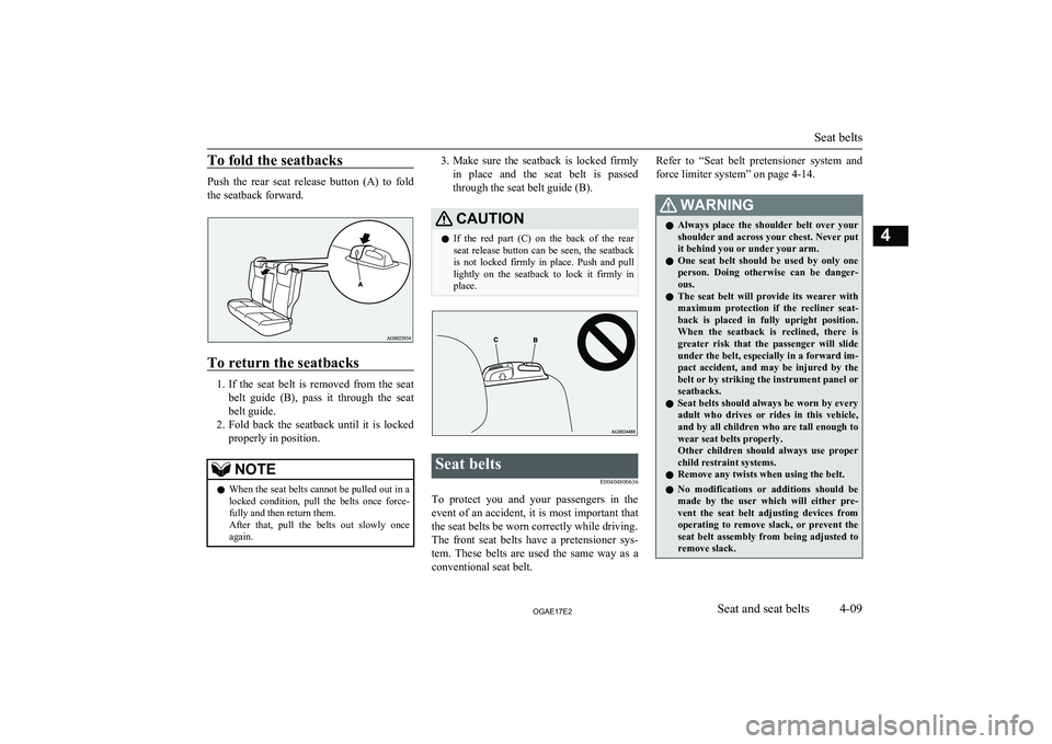
To fold the seatbacks
Push the rear seat release button (A) to fold
the seatback forward.
To return the seatbacks
1. If the seat belt is removed from the seat
belt guide (B), pass it through the seat belt guide.
2. Fold back the seatback until it is locked
properly in position.
NOTEl When the seat belts cannot be pulled out in a
locked condition, pull the belts once force-
fully and then return them.
After that, pull the belts out slowly once again.3. Make sure the seatback is locked firmly
in place and the seat belt is passed
through the seat belt guide (B).CAUTIONl If the red part (C) on the back of the rear
seat release button can be seen, the seatback is not locked firmly in place. Push and pulllightly on the seatback to lock it firmly inplace.Seat belts
E00404800636
To protect you and your passengers in theevent of an accident, it is most important thatthe seat belts be worn correctly while driving.
The front seat belts have a pretensioner sys- tem. These belts are used the same way as a
conventional seat belt.
Refer to “Seat belt pretensioner system and
force limiter system” on page 4-14.WARNINGl Always place the shoulder belt over your
shoulder and across your chest. Never put it behind you or under your arm.
l One seat belt should be used by only one
person. Doing otherwise can be danger- ous.
l The seat belt will provide its wearer with
maximum protection if the recliner seat- back is placed in fully upright position.
When the seatback is reclined, there is
greater risk that the passenger will slide under the belt, especially in a forward im-
pact accident, and may be injured by the
belt or by striking the instrument panel or seatbacks.
l Seat belts should always be worn by every
adult who drives or rides in this vehicle, and by all children who are tall enough towear seat belts properly.
Other children should always use proper child restraint systems.
l Remove any twists when using the belt.
l No modifications or additions should be
made by the user which will either pre-
vent the seat belt adjusting devices from operating to remove slack, or prevent the
seat belt assembly from being adjusted to remove slack.
Seat belts
4-09OGAE17E2Seat and seat belts4