MITSUBISHI COLT 2006 Service Owner's Guide
Manufacturer: MITSUBISHI, Model Year: 2006, Model line: COLT, Model: MITSUBISHI COLT 2006Pages: 364, PDF Size: 11.65 MB
Page 31 of 364
HEATER CONTROL
HEATER, AIR CONDITIONER AND VENTILATION55-7
HEATER CONTROL
M2551000900346
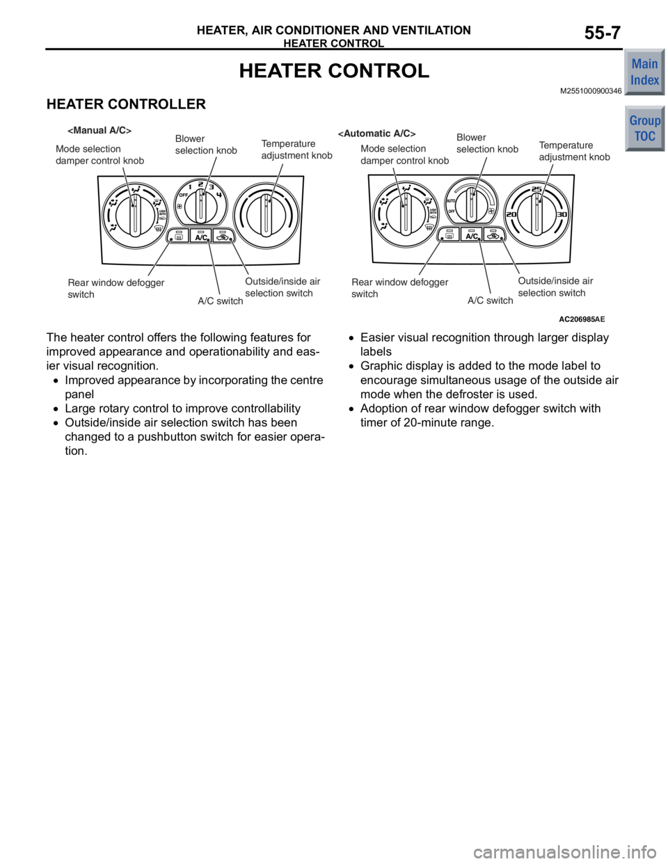
HEATER CONTROLLER
AC206985AE
Mode selection
damper control knob Blower
selection knob
Temperature
adjustment knob
Mode selection
damper control knobBlower
selection knob
Temperature
adjustment knob
Outside/inside air
selection switch
A/C switch
Rear window defogger
switch
Outside/inside air
selection switch
A/C switch
Rear window defogger
switch
The hea
ter control of fe rs the following f eatures for
imp
r oved appea rance and o perationabilit y and eas
-
ier visual recognition .
•Improved appea ran c e by in corpo r ati ng th e cen t re
p
anel
•Larg e rot a ry contro l to impr ove contro llab ility
•Outs ide / inside a i r selection switch has bee n
ch
anged to a p u shb u tton switch for ea sie r opera
-
tion .
•Easier visu al recogn ition throug h larg er display
la
bels
•Graphic display is ad ded to the mode label to
encourag
e simult aneo us usa ge o f the out side air
mode when
the de froste r is used .
•Adoption o f rear win dow defo gger switch with
timer of
20-minute range.
Page 32 of 364

A/C-ECU
HEATER, AIR CONDITIONER AND VENTILATION55-8
A/C-ECU
M2551001200179
CONTROL SYSTEM
The manual and automatic A/Cs have the following
control functions.
ControlManual A/CAutomatic A/C
Automatic wind temperature change controlApplicableApplicable
Automatic outside/inside air selection controlApplicableApplicable
Idle-up controlApplicableApplicable
Cooling fun load controlApplicableApplicable
Cooling controlApplicableApplicable
Detection control for refrigerant leaksApplicableApplicable
MAX A/C controlNot applicableApplicable
Estimation control for compressor torqueApplicableApplicable
Defroster linked controlNot applicableApplicable
AUTOMATIC CHANGE CONTROL OF
BLOW WIND TEMPERATURE
(COMPRESSOR
ENERGY-CONSERVATION CONTROL)
Optimum ON/OFF control of the compressor is
achieved according to the outside/inside air mode,
air temperature (air temperature sensor), and insula
-
tion.
OUTSIDE/INSIDE AIR AUTO SWITCHING
CONTROL
When the A/C is turned on in high ambient tempera-
ture, the recirculation function is automatically acti-
vated to cool down the passenger compartment and
improve fuel consumption.
COOLING FUN LOAD CONTROL
Depending on the A/C load, the cooling fan cycle
time is controlled and the exterior noise in the inter
-
mediary stage is decreased. Also, the load of the
alternator is decreased to improve the fuel economy.
COOLING CONTROL
If air temperature is high, the CVT rotates at a high
speed to prevent deterioration in cooling perform
-
ance.
DETECTION CONTROL FOR
REFRIGERANT LEAKS
When it is judged from the air temperature (air tem-
perature sensor) and the refrigerant pressure (A/C
pressure sensor) that the refrigerant amount is the
specified value or less, or the refrigerant pressure is
abnormal, the compressor is forced to be cut off to
protect the A/C system.
MAX A/C CONTROL
When MAX COOL position is set, automatically the
mode is changed to the inside air mode before the
A/C is turned ON, thereby facilitating the operation
for obtaining maximum cooling performance.
ESTIMATION CONTROL FOR
COMPRESSOR TORQUE
Communication between the engine⋅CVT-ECU and
A/C-ECU is made to control the engine according to
the compressor torque for higher drivability and
reduction in fuel consumption.
FORCIBLE DEFROSTER CONTROL
When the defroster vents are selected, the A/C is
automatically turned ON. At this time, the out
-
side/inside air selection damper is operated to the
fresh-air position to defrost the windshield glass
quickly.
Page 33 of 364

A/C-ECU
HEATER, AIR CONDITIONER AND VENTILATION55-9
COMMUNICATION
The A/C receives the following kinds of signals
through CAN communication.
SignalTransmitter ECU
Engine coolant
temperature signalEngine-CVT-ECU
or Engine-ECU
NOTE: . For further details on CAN, refer to GROUP
54C, CAN
P.54C-2.
DIAGNOSTIC FUNCTION
Code No.Diagnostic itemService data display
contents when
diagnosis code is set
B1011Ambient temperature sensor system (short circuit)20°C
B1012Ambient temperature sensor system (open circuit)
B1021Air thermo sensor system (short circuit)−6°C
B1022Air thermo sensor system (open circuit)
B1082Automatic/manual types abnormal error−
U1073Bus off error−
U1100Engine-CVT-ECU time-out
U1101
U1102ABS-ECU time-out
U1106EPS-ECU time-out
U1109ETACS-ECU time-out
U1120Failure information on engine-CVT-ECU (related to engine)
U1206Flag invalid
Page 34 of 364

A/C-ECU
HEATER, AIR CONDITIONER AND VENTILATION55-10
SERVICE DATA OUTPUT
Item No.Check items
02Ambient temperature sensor
03Air thermo sensor
04A/C pressure sensor
05Water temperature sensor
07Set temperature
08Set temperature (control part set value)
15Outside/Inside air selection damper
20Blower motor
21Blower motor (Target)
30A/C switch
31A/C switch (control part set value)
35Rear window defogger switch (control part set value)
36Blower switch
37Outside/Inside air selection switch
40Abnormal low pressure judgement
41Refrigerant leaks judgement
42DEF position flag
43Forcible DEF position flag
44Forcible DEF DRY flag
ACTUATOR TEST
Item No.Check items
30Outside/Inside air selection damper control motor
31
40Rear defogger switch
41
09Condenser fan
0B
50Idle-up requirement
51
52
Page 35 of 364
DUCTS
HEATER, AIR CONDITIONER AND VENTILATION55-11
DUCTS
M2551001300110
AC313959AB
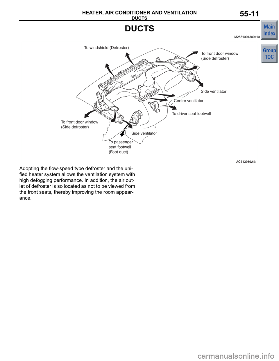
To windshield (Defroster)To front door window
(Side defroster)
Side ventilator
Side ventilator Centre ventilator
To passenger
seat footwell
(Foot duct)
To front door window
(Side defroster)
To driver seat footwell
Ad
optin g the f l ow-sp eed type de froste r and th e uni-
fied heate r syst em allows th e ventilation system with
high
defogg ing p e rformance . In ad dition, the air ou t
-
let of defroster is so located as no t to be vie w e d from
the fron
t sea t s, there b y impro v ing the ro om ap pear
-
ance.
Page 36 of 364
VENTILATION SYSTEM
HEATER, AIR CONDITIONER AND VENTILATION55-12
VENTILATION SYSTEM
M2551002000305
AC206030AB
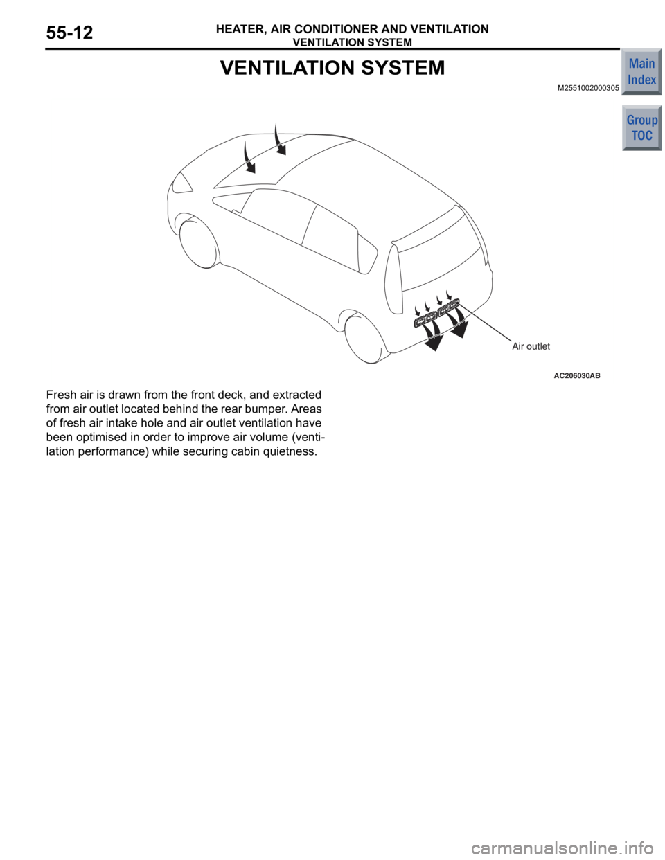
Air outlet
Fresh ai r is drawn fro m the f r ont deck, a nd extracte d
fro
m air ou tlet lo cate d be hind th e re ar bu mp er . Area s
of fresh
air int a ke h o le and a i r outlet vent ilat i on have
been o
p timise d in order to imp r ove air volume (venti
-
lation perfo rman ce) while secu ring cabin quietness.
Page 37 of 364
GROUP 15
INTAKE AND EXHAUST
CONTENTS
AIR INTAKE SYSTEM . . . . . . . . . . . .15-2
AIR DUCT AND AIR CLEANER . . . . . . . . . 15-2
INTERCOOLER <4G1> . . . . . . . . . . . . . . . 15-3
INLET MANIFOLD <4A9> . . . . . . . . . . . . . . 15-4
INLET MANIFOLD <4G1> . . . . . . . . . . . . . 15-4
EXHAUST SYSTEM . . . . . . . . . . . . . .15-5
EXHAUST MANIFOLD <4A9> . . . . . . . . . . 15-5
TURBOCHARGER <4G1> . . . . . . . . . . . . . 15-6
EXHAUST PIPE AND MUFFLER <4A9> . . 15-7
EXHAUST PIPE AND MUFFLER <4G1> . . 15-8
Page 38 of 364
AIR INTAKE SYSTEM
INTAKE AND EXHAUST15-2
AIR INTAKE SYSTEM
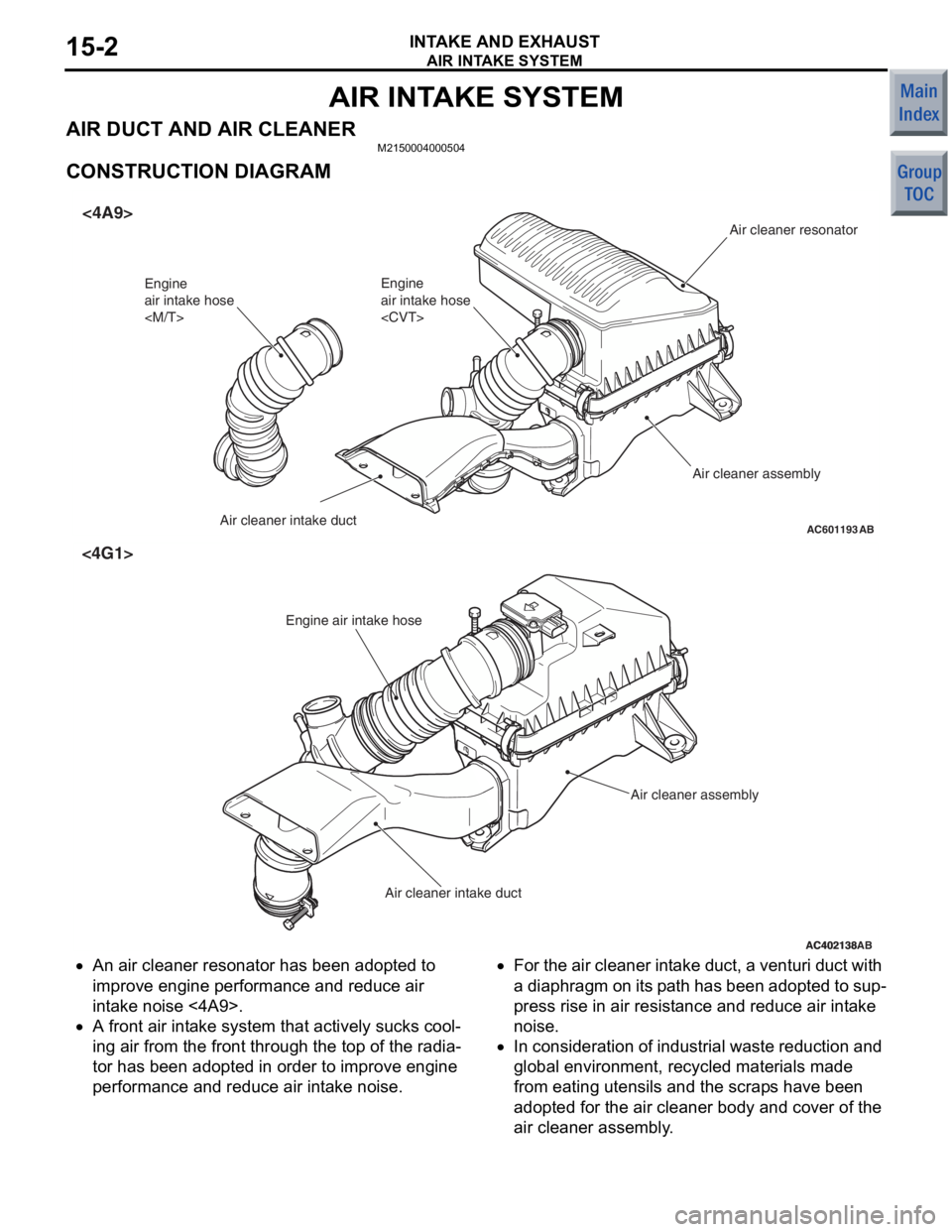
AIR DUCT AND AIR CLEANER M2150004000504
CONSTRUCTION DIAGRAM
AC601193AB
Engine
air intake hose
Air cleaner intake duct
<4A9>
Engine
air intake hose
Air cleaner resonator
AC402138
Engine air intake hose
Air cleaner assembly
Air cleaner intake duct
AB
<4G1>
AC402138
•An air cleaner reson a tor ha s bee n adop ted to
improve eng
ine p e rformance and re duce air
in
t a ke no ise <4A9>.
•A front air int a ke system that actively su cks co ol-
ing air from th e front throug h the to p of th e radia-
tor ha s b een ad opted in ord e r to improve en gine
perf
o rman ce a nd redu ce air int a ke noise.
•For the air clea ner int a ke duct, a ve ntur i d u ct with
a diaphra
g m on it s p a th has been adopte d to su p
-
press rise in air resist ance and reduce air int a ke
noise.
•In considerat ion of ind u strial waste red u ction an d
global environment, re
cyc led mate rials made
from eating ut
ensils and th e scrap s ha ve be en
ado
pted for t he air clean er body and cover of t he
air cleaner a
sse mbly .
Page 39 of 364
AIR INTAKE SYSTEM
INTAKE AND EXHAUST15-3
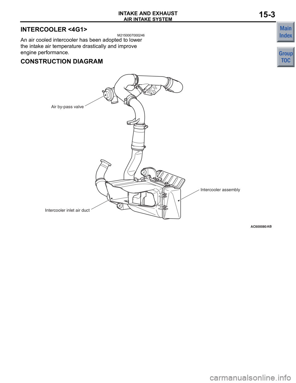
INTERCOOLER <4G1>
M2150007000246
An air cooled intercooler has been adopted to lower
the intake air temperature drastically and improve
engine performance.
CONSTRUCTION DIAGRAM
AC600080AB
Intercooler inlet air ductAir by-pass valve
Intercooler assembly
Page 40 of 364
AIR INTAKE SYSTEM
INTAKE AND EXHAUST15-4
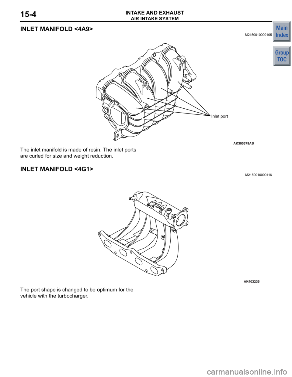
INLET MANIFOLD <4A9>
M2150010000105
AK305379
Inlet port
AB
The inlet manifold is made o f resin. Th e inlet por t s
are cu
rled f o r size a nd weig ht redu ctio n.
INLET MANIFOLD <4G1>
M215001 00001 1 6
AK403235
The port sha pe is ch anged to be o p timum f o r the
vehicle
with th e turbo c harg e r .