MITSUBISHI COLT 2006 Service Owner's Manual
Manufacturer: MITSUBISHI, Model Year: 2006, Model line: COLT, Model: MITSUBISHI COLT 2006Pages: 364, PDF Size: 11.65 MB
Page 21 of 364
WIPER AND WASHER
EXTERIOR51-9
WIPER AND WASHER
WINDSHIELD WIPER AND WASHERM2510007000358
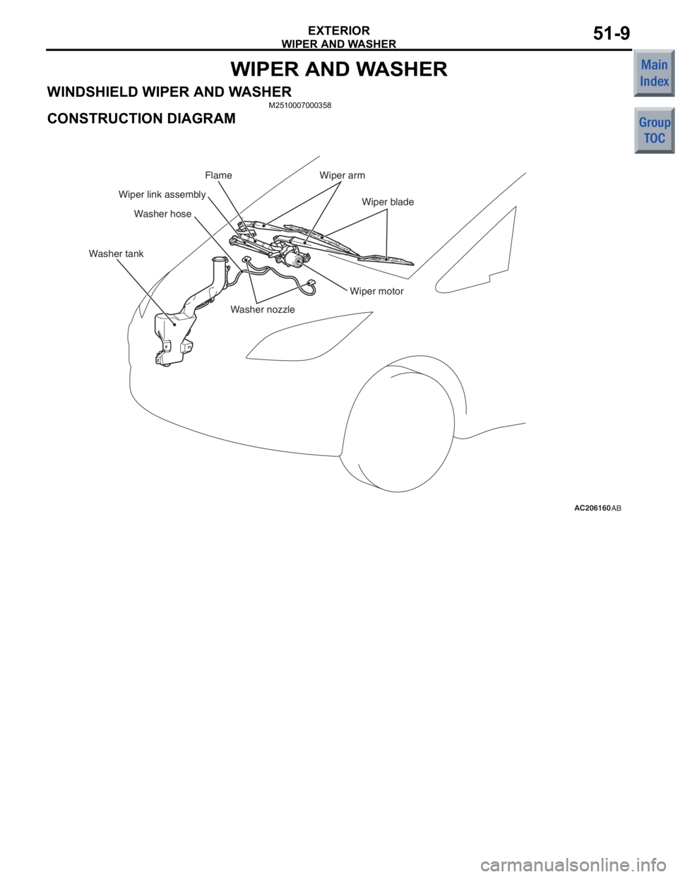
CONSTRUCTION DIAGRAM
AC206160AB
Washer nozzle
Washer hose
Wiper motor
Wiper arm
Wiper blade
Wiper link assembly
Washer tank Flame
Page 22 of 364
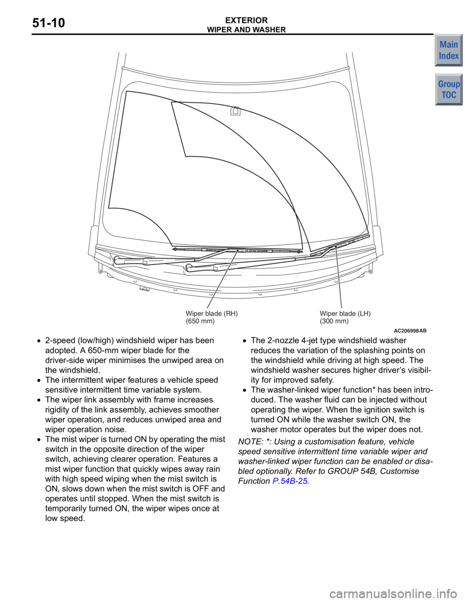
AC206998AB
Wiper blade (RH)
(650 mm)Wiper blade (LH)
(300 mm)
WIPE
R AN D W A SHER
EXTERIOR51-10
•2-speed (low/high) wind shield wip e r has been
ado
pted. A 6 50-mm wipe r blad e for th e
driver-side
wiper minimises the unwiped are a on
the
windshield.
•The intermitte nt wipe r feature s a vehicle spe ed
se
nsitive inte rmit tent time varia b le system.
•The wiper link assemb ly with frame in creases
rig
i dit y of t he link a s sembly , achieves smo o ther
wipe
r operat ion, a nd red u ces unwip ed area and
wipe
r operat ion n o ise.
•The mist wip e r is tu rned ON by o pera t ing the mist
switch in the
opposite direction of the wiper
switch,
achieving cleare r operat ion. F eatures a
mist wiper fun
c tio n that quickly wipe s away rain
with
high spee d wiping when t he mist switch is
ON,
slows down whe n th e mist switch is OFF and
ope
rates until sto pped. When th e mist switch is
temporarily turned
ON, the wiper wip e s o n ce a t
lo
w speed .
•The 2-nozzle 4-je t type windshield wash er
redu
ces the varia t ion of the spla shing point s on
the
windshield while dr iving at high speed. The
wind
shield washer secu res h i gher driver ’ s visibil
-
ity for impro v ed safe ty .
•The washer-linke d wiper function * has b een int r o-
duced. The wash er flu i d can be injected withou t
ope
rating the wip e r . Whe n the ignition switch is
turn
ed ON while t he wash er switch ON, the
washer mo
tor ope rates but th e wiper d oes not.
NOTE: *: Using a cust omisation fea t ure, vehicle
spee
d sen s it ive intermitte nt time variab le wip e r and
wa
sher
-lin ked wiper fun c tio n ca n be e nable d or disa
-
bled optio nally . Refer to GROUP 54 B, Cu stomise
Funct
i on
P.54B-25.
Page 23 of 364
WIPER AND WASHER
EXTERIOR51-11
REAR WIPER AND WASHER
M2510008000403
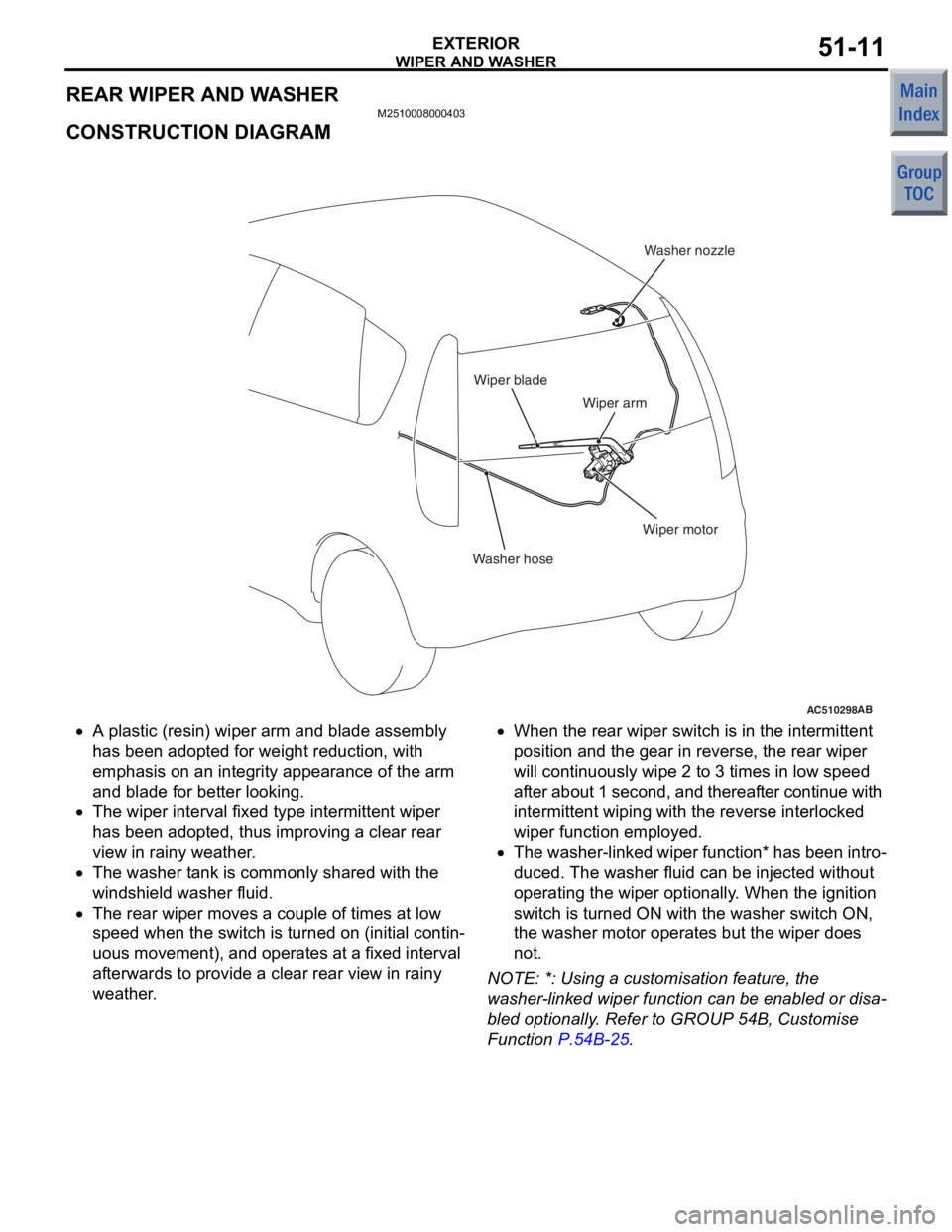
CONSTRUCTION DIAGRAM
AC510298AB
Washer hoseWasher nozzle
Wiper motor
Wiper arm
Wiper blade
•A plastic (resin) wiper arm and
blade assemb ly
has bee
n adop ted for we ight re duct i on, with
emphasis on
an integ r ity appea rance of the arm
and
blad e for be tter looking.
•The wiper interval fixed type intermitte nt wiper
has bee
n adop ted, th us improving a clear re ar
view in
rainy weather .
•The wa sher t a n k is co mmonly sha r ed with the
wind
shield washer fluid.
•The rear wipe r moves a co uple of times at low
sp
eed whe n the switch is turned on (in i tia l contin
-
uous moveme nt), and opera t es at a fixe d interval
af
terwards to pr ovid e a clear rear view in rainy
weathe
r .
•When the re ar wiper switch is in the in termittent
position an
d the g ear in reve rse, th e rear wiper
will co
ntinu ously wipe 2 to 3 times in low spee d
af
ter about 1 second, and thereaf ter contin ue with
in
termittent wiping with the reve rse interlocked
wipe
r function employe d .
•The washer-linke d wiper function * has b een int r o-
duced. The wash er flu i d can be injected withou t
ope
rating the wip e r optionally . Wh en the ignition
switch is tu
rned ON with th e washe r switch ON,
the
wa sher moto r operate s bu t the wiper doe s
not
.
NO TE: *: Using a cust omisation fea t ure, th e
wa
sher
-lin ked wiper fun c tio n ca n be e nable d or disa
-
bled optio nally . Refer to GROUP 54 B, Cu stomise
Funct
i on
P.54B-25.
Page 24 of 364
DOOR MIRROR
EXTERIOR51-12
DOOR MIRROR
M2510008100154
The door mirror is a folded type and has the following
characteristics.
•Features an electric retractable remote controlled
mirror.
•Vehicle speed-dependent automatic return func-
tion.
•A vertically-enlarged mirror has been used for
easy confirmation of safety around the vehicle.
•Aerodynamic door mirror shape have been devel-
oped so that the door glasses and mirrors do not
easily get wet with raindrops while driving in a
rainy day.
•Flag type door mirror shape which secures suffi-
cient distance between the door mirror and delta
pillar has been adopted to reduce the blind spot
area of the forward view.
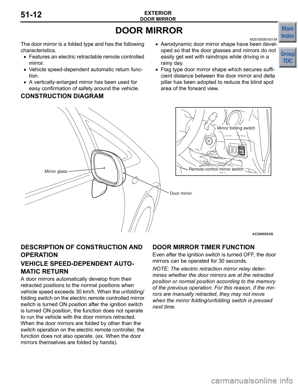
CONSTRUCTION DIAGRAM
AC206693AB
Door mirror
Mirror glass
Remote control mirror switchMirror folding switch
DESCRIPTION OF CONSTRUCTION AND
OPERA
T ION
VEHICLE SPEED-DEPENDENT AUT O-
MATIC RETURN
A d oor mirrors automatically d e velop fro m the i r
retract
ed positions to the norma l positions wh en
ve
h i cle spe e d exce ed s 3 0 km/ h . Wh en t h e un fo ldin g/
fold
in g switch on t h e e l ectr ic re mo te co nt ro lled mirr or
switch is turned
ON po sition af ter the ig nition switch
is tu
rned ON positio n, the funct i on d oes n o t ope rate
to run th
e ve hicle with the do or mirrors retracted.
When th
e door mirro rs are fold ed by other t han th e
s
w itc h ope rat i on o n th e ele c t r i c rem o t e c o n t rol l er , th e
funct
i on d oes n o t also op erate. (ex. W hen the door
mirro
rs the m selve s are fold ed by hands).
DOOR MIRROR TIMER FUNCTION
Even after the ignition swit ch is turned OFF , the d oor
mirro
rs can be operate d for 30 seconds.
NOTE: The electric retraction mirror rela y de ter-
mine s whet her the door mirrors are a t the re tracte d
position
or normal p o sition accordin g to the memory
of the p
r evious operation. F o r this reason, if the mir
-
rors ar e man ually ret r acte d, they ma y not move
wh
en the mirro r fold ing/u n fold ing switch is pressed
next time
.
Page 25 of 364
GROUP 55
HEATER, AIR
CONDITIONER AND
VENTILATION
CONTENTS
GENERAL INFORMATIO N . . . . . . . .55-2
HEATER UNIT . . . . . . . . . . . . . . . . . .55-5
HEATER CONTROL . . . . . . . . . . . . .55-7
A/C-ECU . . . . . . . . . . . . . . . . . . . . . . .55-8
DUCTS . . . . . . . . . . . . . . . . . . . . . . . .55-11
VENTILATION SYSTEM . . . . . . . . . . .55-12
Page 26 of 364

GENERAL INFORMATION
HEATER, AIR CONDITIONER AND VENTILATION55-2
GENERAL INFORMATION
M2551000100759
For the heater and A/C system, the heater, the
blower and the cooling unit are integrated as one unit
to reduce weight and size. For A/C system, the man
-
ual A/C has been adopted.
FEATURES
IMPROVEMENTS IN COMFORT
•Adoption of low noise, large air volume heater
and A/C system
•Adoption of smaller air intake box for larger pas-
senger leg space.
•Optimising the areas of the outside air induction
hole and the air outlet improves ventilation per
-
formance as well as the quietness of the room
•Adoption of clean air filter with deodorant function
for cleaner air in the compartment.
IMPROVEMENTS IN OPERATION
PERFORMANCE
•Inside/outside air selection switch has been
changed to a pushbutton switch.
•Improved operation ability by the enlarged tab on
the dial knob
•Air amount and temperature only are controlled
automatically for easier operation.
RELIABLE VISUAL FIELD
(IMPROVEMENT IN SAFETY)
•Current type defroster nozzle has been adopted
to improve defogging performance (Shortens
windshield fogging time).
•Defroster vents have been integrated to secure
better defogging pattern.
•Black coin drop prevention ribs are used on the
defroster to prevent its reflection on the wind
-
shield, providing sufficient field of vision for safety
IMPROVEMENTS IN FUEL ECONOMY
•Wider condenser area reduces load to the A/C
and improves fuel consumption.
•Energy conservation control using outside air
temperature sensor is adopted for vehicles with
manual A/C as well.
•A small-size, highly-efficient compressor has
been adopted.
•Simpler wiring and weight reduction are achieved
by installation of CAN communication system
GLOBAL ENVIRONMENT PROTECTION
Adoption of HFC134a for refrigerant.
IMPROVEMENTS IN SERVICE QUALITY
•Reduction of refrigerant gas leakage and
improvement in serviceability by incorporating
condenser and receiver
•The layout of refrigerant line for better workability
is adopted.
RESPONSIBILITY IMPROVEMENT
Reliable information transmission is achieved by
connecting A/C-ECU and each ECU via CAN com
-
munication.
Page 27 of 364

GENERAL INFORMATION
HEATER, AIR CONDITIONER AND VENTILATION55-3
SPECIFICATION
ItemSpecification
Heater unit typeTwo-layer full blow air mix method
Heater control typeDial type
A/C switch typePush button type
Compressor typeMSC60CA
RefrigerantTy p eHFC134a
Charge quantity g550 ± 20
PART MANUFACTURER
ItemManufacturer
A/C controller amplifierMitsubishi Heavy Industries Ltd.
Liquid pipe A
Liquid pipe B
Discharge flexible hose
Suction flexible hose
Compressor
Heater control panelAnsei Co., Ltd.
Heater unitDenso Corporation
Air intake box
CondenserZexel Valeo Climate Control
Corporation
Page 28 of 364
GENERAL INFORMATION
HEATER, AIR CONDITIONER AND VENTILATION55-4
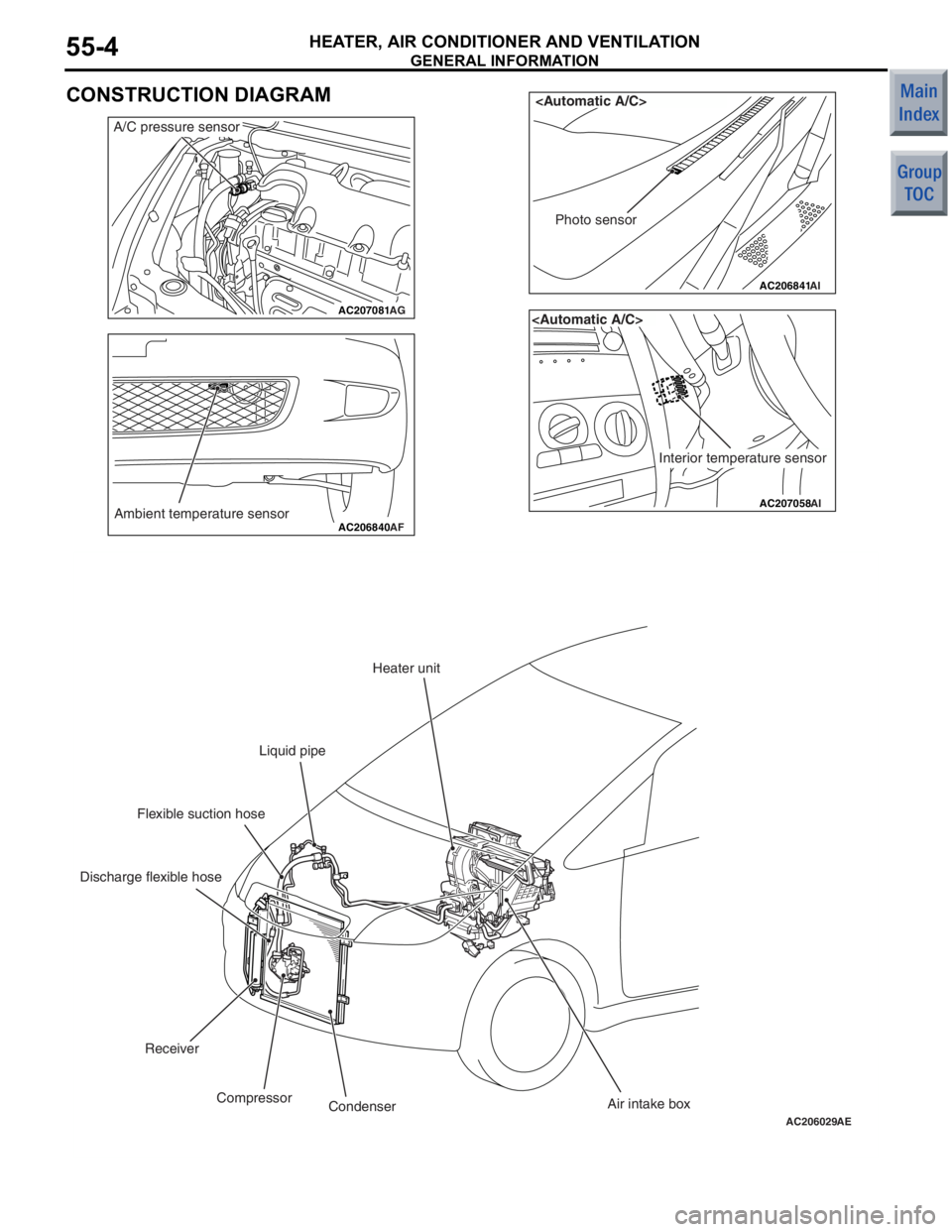
CONSTRUCTION DIAGRAM
AC207081AG
A/C pressure sensor
AC206840Ambient temperature sensorAF
AC206841
AI
Photo sensor
AC207058
Interior temperature sensor
AI
AC206029AE
Heater unit
Liquid pipe
Flexible suction hose
Discharge flexible hose
Receiver Compressor Condenser Air intake box
Page 29 of 364
HEATER UNIT
HEATER, AIR CONDITIONER AND VENTILATION55-5
HEATER UNIT
M2551000800219
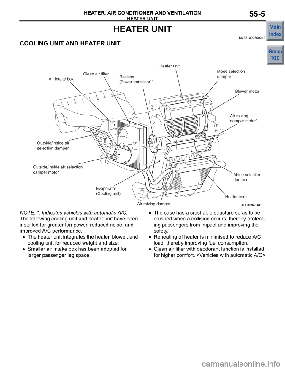
COOLING UNIT AND HEATER UNIT
AC313940AB
Air intake boxResistor
(Power transistor)*Heater unit
Mode selection
damper
Blower motor
Air mixing
damper motor*
Mode selection
damper
Heater core
Air mixing damper
Evaporator
(Cooling unit)
Outside/Inside air
selection damper
Outside/Inside air selection
damper motor
Clean air filter
NO TE: *: Indicat e s vehicles with a u tomatic A/C.
The following co oling unit and heate r unit have been
inst
alled for grea ter fan p o wer , red u ced noise, an d
imp
r oved A/C p e rformance .
•The h eat er unit int egra t es t he hea ter , b l owe r , and
co
oling unit for re duce d weigh t and size.
•Smaller air int a ke b o x ha s be en ado pted fo r
la
rger p a ssenge r leg sp ace .
•The case has a crush able structure so as to be
crushe
d when a collision occurs, t hereby prote c t
-
ing p a ssenger s from imp a ct an d improving t he
safety
.
•Rehea ting of heat er is minimise d to red u ce A/ C
lo
ad, the r eby imp r oving fue l co nsumption.
•Clean air filter with deod orant function is inst alled
for h
i ghe r comfort.
Page 30 of 364
HEATER UNIT
HEATER, AIR CONDITIONER AND VENTILATION55-6
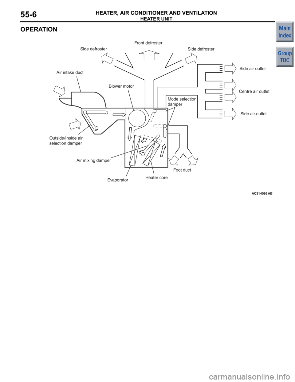
OPERATION
AC314092AB
Front defrosterSide defroster
Side defroster
Side air outlet
Centre air outlet Side air outlet
Air intake duct
Blower motor
Outside/Inside air
selection damper Air mixing damper
Evaporator Heater coreFoot duct
Mode selection
damper