MITSUBISHI COLT 2011 Owner's Manual (in English)
Manufacturer: MITSUBISHI, Model Year: 2011, Model line: COLT, Model: MITSUBISHI COLT 2011Pages: 274, PDF Size: 17.88 MB
Page 141 of 274
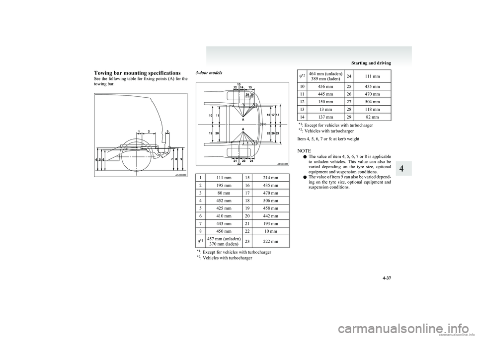
Towing bar mounting specifications
See the following table for fixing points (A) for the
towing bar.3-door models1111 mm15214 mm2195 mm16435 mm380 mm17470 mm4452 mm18506 mm5425 mm19458 mm6410 mm20442 mm7443 mm21193 mm8450 mm2210 mm9 *1457 mm (unladen)
370 mm (laden)23222 mm*1 : Except for vehicles with turbocharger
*2 : Vehicles with turbocharger9*2464 mm (unladen)
389 mm (laden)24111 mm10456 mm25435 mm11445 mm26470 mm12150 mm27504 mm1313 mm28118 mm14137 mm2982 mm*1 : Except for vehicles with turbocharger
*2 : Vehicles with turbocharger
Item 4, 5, 6, 7 or 8: at kerb weight
NOTE l The value of item 4, 5, 6, 7 or 8 is applicable
to unladen vehicles. This value can also be
varied depending on the tyre size, optional
equipment and suspension conditions.
l The value of item 9 can also be varied depend-
ing on the tyre size, optional equipment and
suspension conditions.
Starting and driving
4-37
4
Page 142 of 274
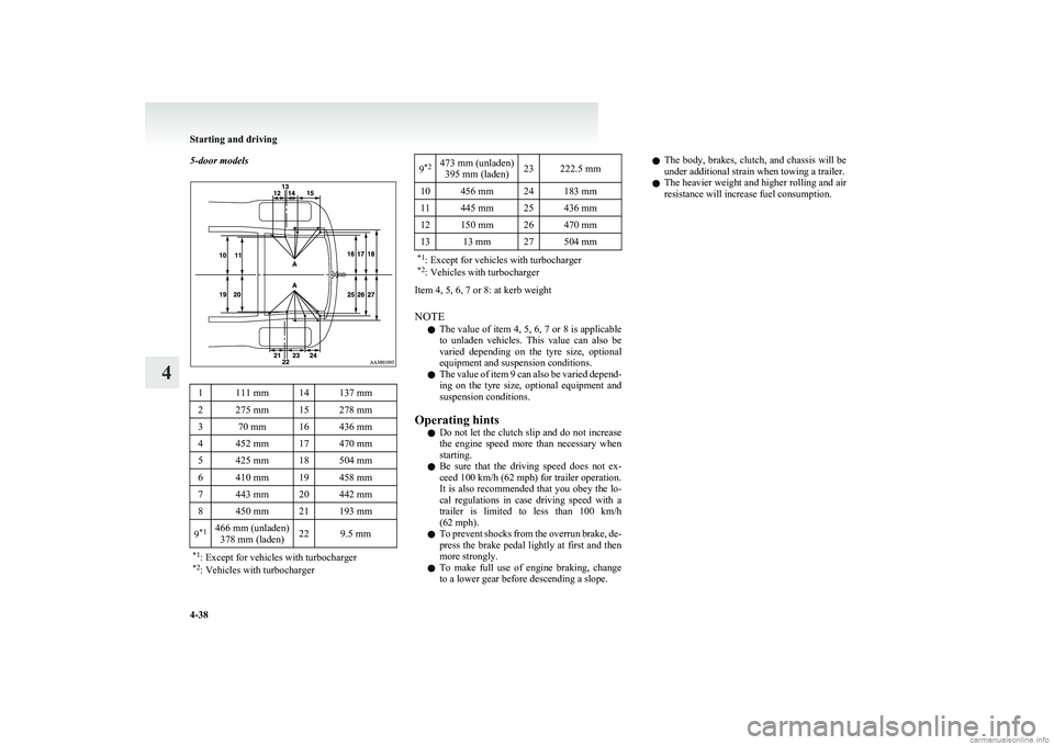
5-door models1111 mm14137 mm2275 mm15278 mm370 mm16436 mm4452 mm17470 mm5425 mm18504 mm6410 mm19458 mm7443 mm20442 mm8450 mm21193 mm9*1466 mm (unladen)
378 mm (laden)229.5 mm*1 : Except for vehicles with turbocharger
*2 : Vehicles with turbocharger9*2473 mm (unladen)
395 mm (laden)23222.5 mm10456 mm24183 mm11445 mm25436 mm12150 mm26470 mm1313 mm27504 mm*1 : Except for vehicles with turbocharger
*2 : Vehicles with turbocharger
Item 4, 5, 6, 7 or 8: at kerb weight
NOTE l The value of item 4, 5, 6, 7 or 8 is applicable
to unladen vehicles. This value can also be
varied depending on the tyre size, optional
equipment and suspension conditions.
l The value of item 9 can also be varied depend-
ing on the tyre size, optional equipment and
suspension conditions.
Operating hints l Do not let the clutch slip and do not increase
the engine speed more than necessary when
starting.
l Be sure that the driving speed does not ex-
ceed 100 km/h (62 mph) for trailer operation.
It is also recommended that you obey the lo-
cal regulations in case driving speed with a
trailer is limited to less than 100 km/h
(62 mph).
l To prevent shocks from the overrun brake, de-
press the brake pedal lightly at first and then
more strongly.
l To make full use of engine braking, change
to a lower gear before descending a slope.
l The body, brakes, clutch, and chassis will be
under additional strain when towing a trailer.
l The heavier weight and higher rolling and air
resistance will increase fuel consumption.
Starting and driving
4-38
4
Page 143 of 274
Ventilators.................................................................................... 5-02
Heater*..........................................................................................5-04
Automatic air conditioning* ......................................................... 5-07
Important operation tips for the air conditioning..........................5-11
Air purifier .................................................................................... 5-12
LW/MW/FM electronic tuning radio with CD player* ................5-12
To use the external audio input function ......................................5-27
Steering wheel audio remote control switches* ...........................5-28
Error codes .................................................................................... 5-30
Handling of compact discs ........................................................... 5-32
Antenna ......................................................................................... 5-33
Digital clock* ............................................................................... 5-34
Sun visors ..................................................................................... 5-36
Vanity mirror ................................................................................ 5-37
Accessory socket .......................................................................... 5-37
Interior lamps ................................................................................ 5-38
Storage spaces...............................................................................5-39
Cup holder .................................................................................... 5-42
Rear shelf panel* .......................................................................... 5-42
Coat hooks* .................................................................................. 5-43For pleasant driving5
Page 144 of 274
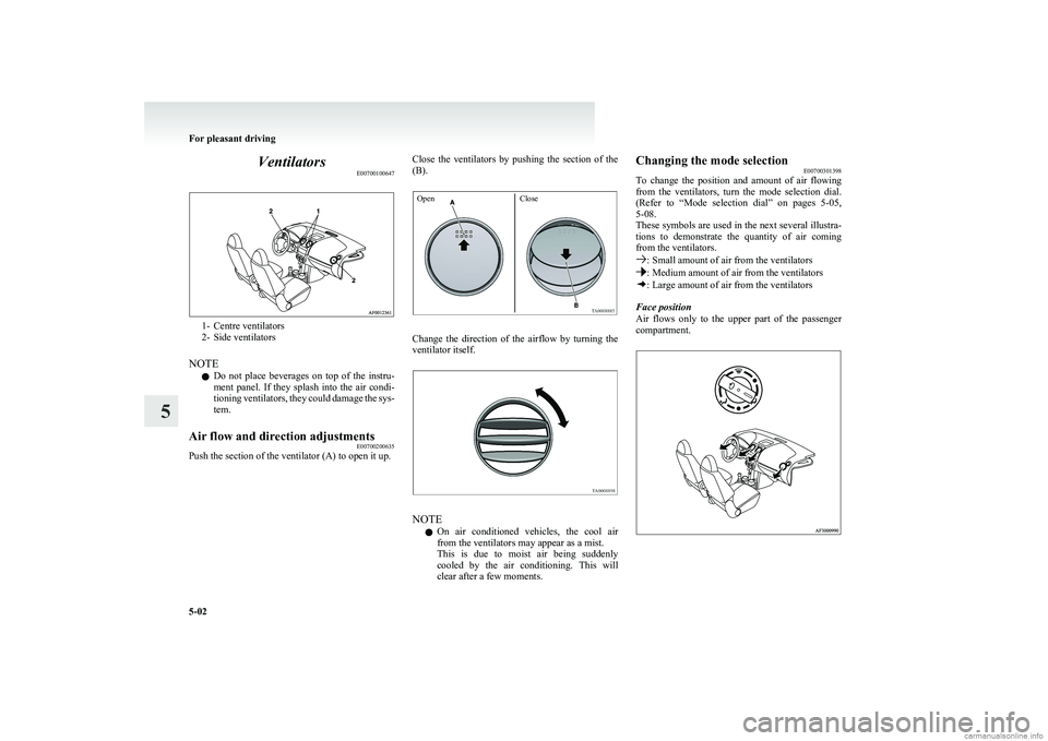
VentilatorsE00700100647
1- Centre ventilators
2- Side ventilators
NOTE l Do not place beverages on top of the instru-
ment panel. If they splash into the air condi-
tioning ventilators, they could damage the sys-
tem.
Air flow and direction adjustments E00700200635
Push the section of the ventilator (A) to open it up.
Close the ventilators by pushing the section of the
(B).OpenClose
Change the direction of the airflow by turning the
ventilator itself.
NOTE
l On air conditioned vehicles, the cool air
from the ventilators may appear as a mist.
This is due to moist air being suddenly
cooled by the air conditioning. This will
clear after a few moments.
Changing the mode selection E00700301398
To change the position and amount of air flowing
from the ventilators, turn the mode selection dial.
(Refer to “Mode selection dial” on pages 5-05,
5-08.
These symbols are used in the next several illustra-
tions to demonstrate the quantity of air coming
from the ventilators.
: Small amount of air from the ventilators: Medium amount of air from the ventilators: Large amount of air from the ventilators
Face position
Air flows only to the upper part of the passenger
compartment.
For pleasant driving
5-02
5
Page 145 of 274
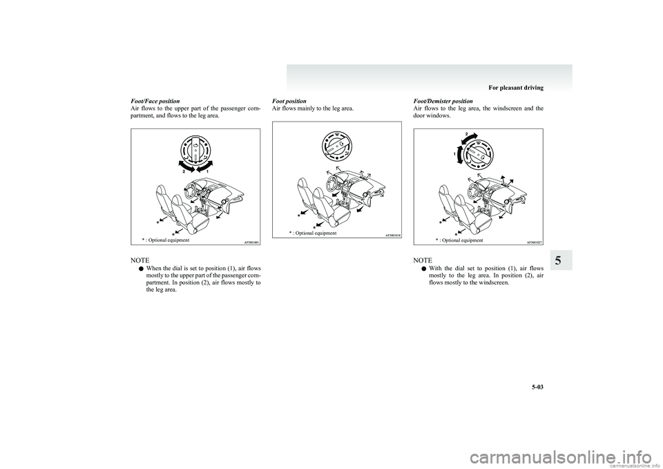
Foot/Face position
Air flows to the upper part of the passenger com-
partment, and flows to the leg area.* : Optional equipment
NOTE
l When the dial is set to position (1), air flows
mostly to the upper part of the passenger com-
partment. In position (2), air flows mostly to
the leg area.
Foot position
Air flows mainly to the leg area.* : Optional equipmentFoot/Demister position
Air flows to the leg area, the windscreen and the
door windows.* : Optional equipment
NOTE
l With the dial set to position (1), air flows
mostly to the leg area. In position (2), air
flows mostly to the windscreen.
For pleasant driving
5-03
5
Page 146 of 274
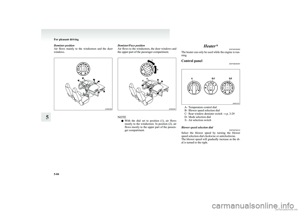
Demister position
Air flows mainly to the windscreen and the door
windows.Demister/Face position
Air flows to the windscreen, the door windows and
the upper part of the passenger compartment.
NOTE
l With the dial set to position (1), air flows
mostly to the windscreen. In position (2), air
flows mostly to the upper part of the passen-
ger compartment.
Heater* E00700500090
The heater can only be used while the engine is run-
ning.Control panel E00700600495
A- Temperature control dial
B- Blower speed selection dial
C- Rear window demister switch ® p. 3-29
D- Mode selection dial E- Air selection switch
Blower speed selection dial E00700700210
Select the blower speed by turning the blower
speed selection dial clockwise or anticlockwise.
The blower speed will gradually increase as the di-
al is turned to the right.
For pleasant driving
5-04
5
Page 147 of 274
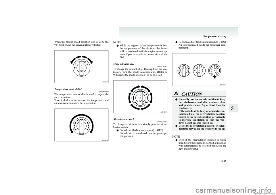
When the blower speed selection dial is set to the
“0” position, all fan-driven airflow will stop.Temperature control dial E00700900300
The temperature control dial is used to adjust the
air temperature.
Turn it clockwise to increase the temperature and
anticlockwise to reduce the temperature.
NOTE
l While the engine coolant temperature is low,
the temperature of the air from the heater
will be cool/cold until the engine warms up,
even if you have selected warm air with the
dial.Mode selection dial E00701100325
To change the amount of air flowing from the ven-
tilators, turn the mode selection dial. (Refer to
“Changing the mode selection” on page 5-02.)
Air selection switch E00701300662
To change the air selection, simply press the air se-
lection switch.
l Outside air {Indication lamp (A) is OFF}
Outside air is introduced into the passenger
compartment.
l Recirculated air {Indication lamp (A) is ON}
Air is recirculated inside the passenger com-
partment.CAUTIONl Normally, use the outside position to keep
the windscreen and side windows clear
and quickly remove fog or frost from the
windscreen.
If the outside air is dusty or otherwise con-
taminated use the recirculation position.
Switch to the outside position periodically
to increase ventilation so that the win-
dows do not become fogged up.
l Use of the recirculation position for exten-
ded time may cause the windows to fog up.
NOTE
l Even if the recirculation position is being
used before the engine is stopped, outside air
will automatically be selected following the
next engine startup.
For pleasant driving
5-05
5
Page 148 of 274
Operating the heater systemE00701800393
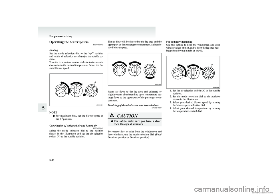
Heating
Set the mode selection dial to the “
” position
and set the air selection switch (A) to the outside po-
sition.
Turn the temperature control dial clockwise or anti-
clockwise to the desired temperature. Select the de-
sired blower speed.
NOTE
l For maximum heat, set the blower speed at
the 3 rd
position.
Combination of unheated air and heated air
E00702000389
Select the mode selection dial to the position
shown in the illustration and set the air selection
switch (A) to the outside position.
The air flow will be directed to the leg area and the
upper part of the passenger compartment. Select de-
sired blower speed.
Warm air flows to the leg area and unheated or
slightly warm air (depending upon temperature set-
ting) flows to the upper part of the passenger com-
partment.
Demisting of the windscreen and door windows E00702100683CAUTIONlFor safety, make sure you have a clear
view through all windows.
To remove frost or mist from the windscreen and
door windows, use the mode selection dial. (Foot/
Demister position or Demister position)
For ordinary demisting
Use this setting to keep the windscreen and door
windows clear of mist, and to keep the leg area heat-
ing (when driving in rain or snow).
1. Set the air selection switch (A) to the outside
position.
2. Set the mode selection dial to the position
shown in the illustration.
3. Select your desired blower speed by turning
the blower speed selection dial.
4. Select your desired temperature by turning
the temperature control dial.
For pleasant driving
5-06
5
Page 149 of 274
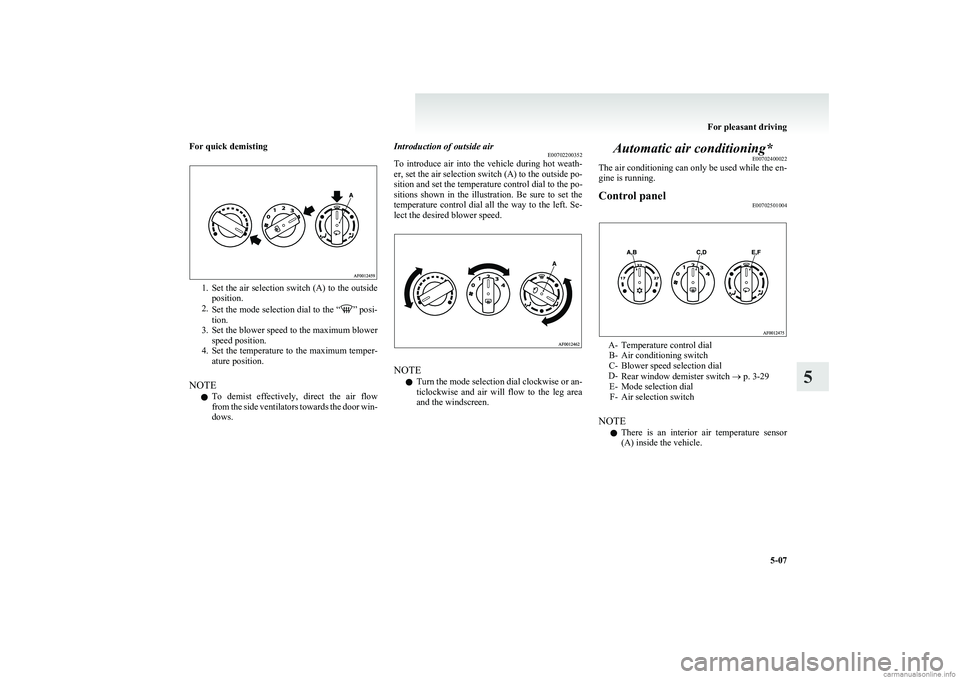
For quick demisting
1.Set the air selection switch (A) to the outside
position.
2. Set the mode selection dial to the “
” posi-
tion.
3. Set the blower speed to the maximum blower
speed position.
4. Set the temperature to the maximum temper-
ature position.
NOTE l To demist effectively, direct the air flow
from the side ventilators towards the door win-
dows.
Introduction of outside air E00702200352
To introduce air into the vehicle during hot weath-
er, set the air selection switch (A) to the outside po-
sition and set the temperature control dial to the po-
sitions shown in the illustration. Be sure to set the
temperature control dial all the way to the left. Se-
lect the desired blower speed.
NOTE
l Turn the mode selection dial clockwise or an-
ticlockwise and air will flow to the leg area
and the windscreen.
Automatic air conditioning* E00702400022
The air conditioning can only be used while the en-
gine is running.Control panel E00702501004
A- Temperature control dial
B- Air conditioning switch
C- Blower speed selection dial
D- Rear window demister switch ® p. 3-29
E- Mode selection dial F- Air selection switch
NOTE l There is an interior air temperature sensor
(A) inside the vehicle.
For pleasant driving
5-07
5
Page 150 of 274
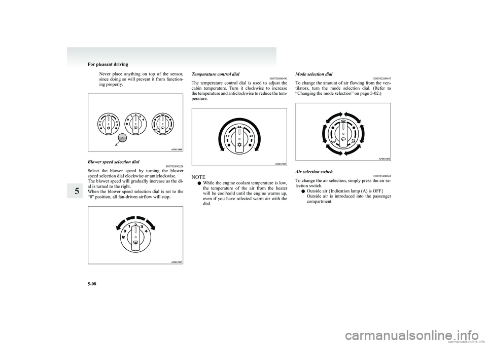
Never place anything on top of the sensor,
since doing so will prevent it from function-
ing properly.Blower speed selection dial E00702800329
Select the blower speed by turning the blower
speed selection dial clockwise or anticlockwise.
The blower speed will gradually increase as the di-
al is turned to the right.
When the blower speed selection dial is set to the
“0” position, all fan-driven airflow will stop.
Temperature control dial E00703000490
The temperature control dial is used to adjust the
cabin temperature. Turn it clockwise to increase
the temperature and anticlockwise to reduce the tem-
perature.
NOTE
l While the engine coolant temperature is low,
the temperature of the air from the heater
will be cool/cold until the engine warms up,
even if you have selected warm air with the
dial.
Mode selection dial E00703200447
To change the amount of air flowing from the ven-
tilators, turn the mode selection dial. (Refer to
“Changing the mode selection” on page 5-02.)Air selection switch E00703400641
To change the air selection, simply press the air se-
lection switch.
l Outside air {Indication lamp (A) is OFF}
Outside air is introduced into the passenger
compartment.
For pleasant driving
5-08
5