steering MITSUBISHI COLT 2011 (in English) User Guide
[x] Cancel search | Manufacturer: MITSUBISHI, Model Year: 2011, Model line: COLT, Model: MITSUBISHI COLT 2011Pages: 274, PDF Size: 17.88 MB
Page 74 of 274
WARNINGlIf any of the following conditions occurs,
the SRS and/or seat belt pretensioners
are not working properly, and we recom-
mend you to have it inspected by a
MITSUBISHI MOTORS Authorized
Service Point immediately. •The SRS warning lamp does not illu-
minate when you start the vehicle.
• The SRS warning lamp does not go
out after several seconds.
• The SRS warning lamp illuminates
while driving.SRS servicing E00407900784WARNINGlWe recommend any maintenance per-
formed on or near the components of the
SRS to be performed by a MITSUBISHI
MOTORS Authorized Service Point.
Improper work on the SRS components
or wiring could result in inadvertent de-
ployment of the airbags, or could render
the SRS inoperative; either situation
could result in serious injury.
l Do not modify your steering wheel, seat
belt retractor or any other SRS compo-
nents. For example, replacement of the
steering wheel, or modifications to the
front bumper or body structure can ad-
versely affect SRS performance and lead
to possible injury.WARNINGl If your vehicle has received any damage,
we recommend you to have the SRS in-
spected to ensure it is in proper working
order.
l On vehicles with the side airbags, do not
modify your front seats, centre pillar and
centre console.
It can adversely affect SRS performance
and lead to possible injury.
Also, if you have found any tear or open
seam in the seat fabric at the portion near
the side airbag, we recommend you to
have the seat inspected.
l On vehicles with the curtain airbags, if
you have found any scratch, crack or dam-
age to the portion of the front and rear pil-
lars and roof side rail, we recommend
you to have the SRS inspected by a
MITSUBISHI MOTORS Authorized
Service Point.
NOTE
l When you transfer ownership of the vehicle
to some other person, we urge you to alert
the new owner that it is equipped with the
SRS and refer that owner to the applicable
section in this owner’s manual.
l If you junk or scrap the vehicle, we urge you
to first take the vehicle to a MITSUBISHI
MOTORS Authorized Service Point so that
the SRS can be rendered safe.
Seat and seat belts
2-34
2
Page 90 of 274
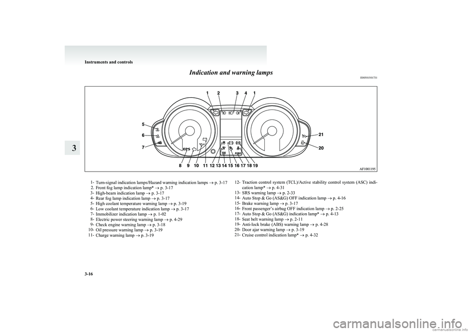
Indication and warning lampsE005015017311-Turn-signal indication lamps/Hazard warning indication lamps ® p. 3-17
2. Front fog lamp indication lamp* ® p. 3-17
3- High-beam indication lamp ® p. 3-17
4- Rear fog lamp indication lamp ® p. 3-17
5- High coolant temperature warning lamp ® p. 3-19
6- Low coolant temperature indication lamp ® p. 3-17
7- Immobilizer indication lamp ® p. 1-02
8- Electric power steering warning lamp ® p. 4-29
9- Check engine warning lamp ® p. 3-18
10- Oil pressure warning lamp ® p. 3-19
11- Charge warning lamp ® p. 3-1912- Traction control system (TCL)/Active stability control system (ASC) indi-
cation lamp* ® p. 4-31
13- SRS warning lamp ® p. 2-33
14- Auto Stop & Go (AS&G) OFF indication lamp ® p. 4-16
15- Brake warning lamp ® p. 3-17
16- Front passenger’s airbag OFF indication lamp ® p. 2-25
17- Auto Stop & Go (AS&G) indication lamp* ® p. 4-13
18- Seat belt warning lamp ® p. 2-11
19- Anti-lock brake (ABS) warning lamp ® p. 4-28
20- Door ajar warning lamp ® p. 3-19
21- Cruise control indication lamp* ® p. 4-32
Instruments and controls
3-16
3
Page 97 of 274
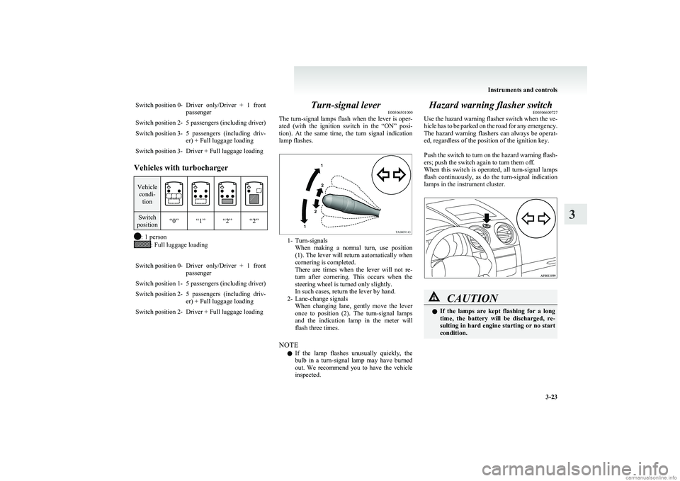
Switch position 0-Driver only/Driver + 1 front
passengerSwitch position 2-5 passengers (including driver)Switch position 3-5 passengers (including driv-
er) + Full luggage loadingSwitch position 3-Driver + Full luggage loading
Vehicles with turbocharger
Vehicle condi- tionSwitch
position“0”“1”“2”“2”
: 1 person: Full luggage loading
Switch position 0-Driver only/Driver + 1 front
passengerSwitch position 1-5 passengers (including driver)Switch position 2-5 passengers (including driv-
er) + Full luggage loadingSwitch position 2-Driver + Full luggage loadingTurn-signal lever E00506501000
The turn-signal lamps flash when the lever is oper-
ated (with the ignition switch in the “ON” posi-
tion). At the same time, the turn signal indication
lamp flashes.
1- Turn-signals When making a normal turn, use position
(1). The lever will return automatically when
cornering is completed.
There are times when the lever will not re-
turn after cornering. This occurs when the
steering wheel is turned only slightly.
In such cases, return the lever by hand.
2- Lane-change signals When changing lane, gently move the lever
once to position (2). The turn-signal lamps
and the indication lamp in the meter will
flash three times.
NOTE l If the lamp flashes unusually quickly, the
bulb in a turn-signal lamp may have burned
out. We recommend you to have the vehicle
inspected.
Hazard warning flasher switch E00506600727
Use the hazard warning flasher switch when the ve-
hicle has to be parked on the road for any emergency.
The hazard warning flashers can always be operat-
ed, regardless of the position of the ignition key.
Push the switch to turn on the hazard warning flash-
ers; push the switch again to turn them off.
When this switch is operated, all turn-signal lamps
flash continuously, as do the turn-signal indication
lamps in the instrument cluster.CAUTIONl If the lamps are kept flashing for a long
time, the battery will be discharged, re-
sulting in hard engine starting or no start
condition.
Instruments and controls
3-23
3
Page 104 of 274
CAUTIONlTo avoid unnecessary discharge of the bat-
tery, do not use the rear window demister
during starting of the engine or when the
engine is not running. Turn the demister
off immediately after the window is clear.
l When cleaning the inside of the rear win-
dow, use a soft cloth and wipe gently
along the heater wires, being careful not
to damage the wires.
l Do not allow objects to touch the inside of
the rear window glass, damaged or bro-
ken wires may result.Horn switch E00508000581
Pressing the “
” mark on the steering wheel, cau-
ses the horn to sound.Instruments and controls
3-30
3
Page 105 of 274
Economical driving.......................................................................4-02
Driving, alcohol and drugs ........................................................... 4-02
Safe driving techniques ................................................................ 4-03
Running-in recommendations.......................................................4-04
Parking brake ................................................................................ 4-06
Parking .......................................................................................... 4-07
Steering wheel height adjustment .................................................4-07
Inside rear-view mirror ................................................................. 4-08
Outside rear-view mirrors ............................................................. 4-08
Ignition switch .............................................................................. 4-10
Steering wheel lock ...................................................................... 4-11
Starting..........................................................................................4-11
Auto Stop & Go (AS&G) system* ...............................................4-13
Manual transmission ..................................................................... 4-16
Automated manual transmission ..................................................4-19
How to drive a vehicle with an automated manual trans- mission......................................................................................4-22
Braking ......................................................................................... 4-25
Emergency stop signal system ...................................................... 4-26
Brake assist system ....................................................................... 4-27
Anti-lock brake system (ABS) ..................................................... 4-27
Electric power steering system ..................................................... 4-29
Traction control system (TCL)/Active stability control system (ASC)* ......................................................................... 4-30
Cruise control* ............................................................................. 4-32
Cargo loads ................................................................................... 4-36
Trailer towing ............................................................................... 4-36Starting and driving4
Page 111 of 274
ParkingE00600601521
Parking on a hill
To prevent the vehicle from rolling, follow these
procedures:
Parking on a downhill slope
Turn the front wheels towards the kerb and move
the vehicle forward until the kerb side wheel gently
touches the kerb.
Apply the parking brake and place the gearshift lev-
er into the “R” (Reverse) position (with manual
transmission) or the allshift lever into the “R” (Re-
verse) position (with automated manual transmis-
sion).
If necessary, apply chocks to wheels.
Parking on an uphill slope
Turn the front wheels away from the kerb and
move the vehicle back until the kerb side wheel gen-
tly touches the kerb.
Apply the parking brake and place the gearshift lev-
er into the 1 st
position (with manual transmission)
or the allshift lever into the “S” (Stand by) position
(with automated manual transmission).
If necessary, apply chocks to wheels.
NOTE l If your vehicle has an automated manual trans-
mission, place the allshift lever in the “S”
(Stand by) position or “R” (Reverse) position
before stopping the engine.
If you move the allshift lever after stopping
the engine, a gearshift will not take place.Parking with the engine running
Never leave the engine running while you take a
short sleep/rest. Also, never leave the engine run-
ning in a closed or poorly ventilated place.WARNINGl Leaving the engine running risks injury
or death from accidentally moving the
gearshift lever (manual transmission) or
the allshift lever (automated manual trans-
mission) or the accumulation of toxic ex-
haust fumes on the passenger compart-
ment.
Where you park
Your front bumper can be damaged if you scrape it
over kerbs or parking stop blocks. Be careful when
travelling up or down steep slopes where your bump-
er can scrape the road.
WARNINGl Do not park your vehicle in areas where
combustible materials such as dry grass
or leaves can come in contact with a hot
exhaust, since a fire could occur.
When leaving the vehicle
Always remove the key from the ignition switch
and lock all doors and the tailgate when leaving the
vehicle unattended.
Always try to park your vehicle in a well lit area.
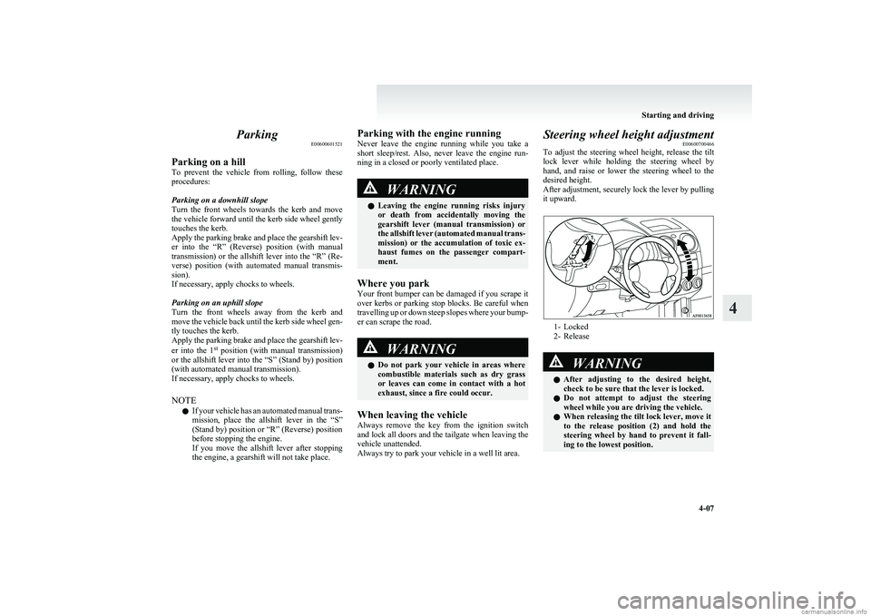
Steering wheel height adjustment E00600700466
To adjust the steering wheel height, release the tilt
lock lever while holding the steering wheel by
hand, and raise or lower the steering wheel to the
desired height.
After adjustment, securely lock the lever by pulling
it upward.
1- Locked
2- Release
WARNINGl After adjusting to the desired height,
check to be sure that the lever is locked.
l Do not attempt to adjust the steering
wheel while you are driving the vehicle.
l When releasing the tilt lock lever, move it
to the release position (2) and hold the
steering wheel by hand to prevent it fall-
ing to the lowest position.
Starting and driving
4-07
4
Page 114 of 274
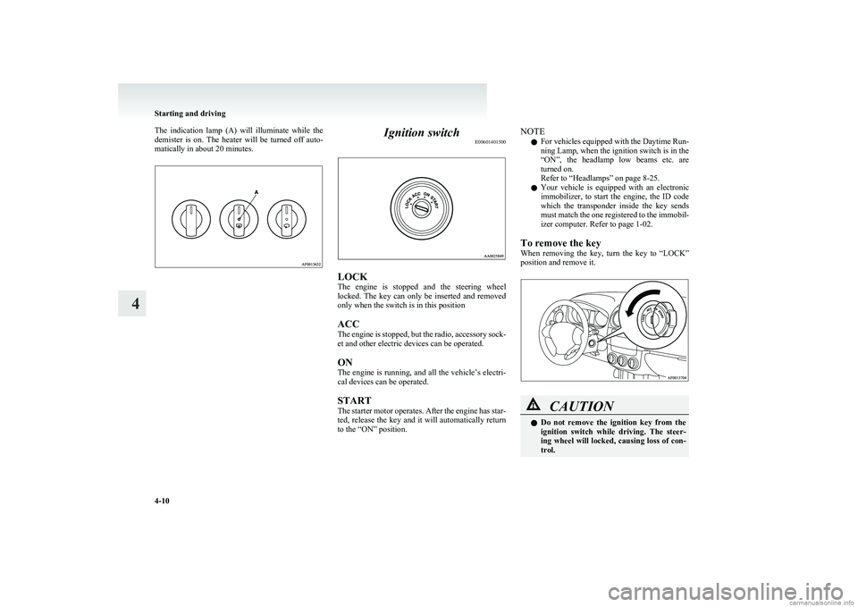
The indication lamp (A) will illuminate while the
demister is on. The heater will be turned off auto-
matically in about 20 minutes.Ignition switch E00601401500
LOCK
The engine is stopped and the steering wheel
locked. The key can only be inserted and removed
only when the switch is in this position
ACC
The engine is stopped, but the radio, accessory sock-
et and other electric devices can be operated.
ON
The engine is running, and all the vehicle’s electri-
cal devices can be operated.
START
The starter motor operates. After the engine has star-
ted, release the key and it will automatically return
to the “ON” position.
NOTE
l For vehicles equipped with the Daytime Run-
ning Lamp, when the ignition switch is in the
“ON”, the headlamp low beams etc. are
turned on.
Refer to “Headlamps” on page 8-25.
l Your vehicle is equipped with an electronic
immobilizer, to start the engine, the ID code
which the transponder inside the key sends
must match the one registered to the immobil-
izer computer. Refer to page 1-02.
To remove the key
When removing the key, turn the key to “LOCK”
position and remove it.CAUTIONl Do not remove the ignition key from the
ignition switch while driving. The steer-
ing wheel will locked, causing loss of con-
trol.
Starting and driving
4-10
4
Page 115 of 274
CAUTIONlIf the engine is stopped while driving, the
brake servomechanism will cease to func-
tion and braking efficiency will deterio-
rate. Also, the power steering system will
not function and it will require greater
manual effort to operate the steering.
l Do not leave the key in the “ON” position
for a long time when the engine is not run-
ning, doing so will cause the battery to be
discharged.
l Do not turn the key to the “START” posi-
tion when the engine is running, doing so
could damage the starter motor.Steering wheel lock E00601500605
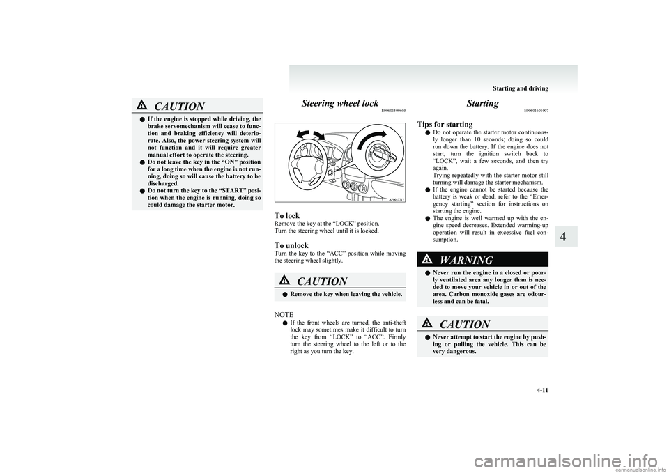
To lock
Remove the key at the “LOCK” position.
Turn the steering wheel until it is locked.
To unlock
Turn the key to the “ACC” position while moving
the steering wheel slightly.
CAUTIONl Remove the key when leaving the vehicle.
NOTE
l If the front wheels are turned, the anti-theft
lock may sometimes make it difficult to turn
the key from “LOCK” to “ACC”. Firmly
turn the steering wheel to the left or to the
right as you turn the key.
Starting E00601601007
Tips for starting l Do not operate the starter motor continuous-
ly longer than 10 seconds; doing so could
run down the battery. If the engine does not
start, turn the ignition switch back to
“LOCK”, wait a few seconds, and then try
again.
Trying repeatedly with the starter motor still
turning will damage the starter mechanism.
l If the engine cannot be started because the
battery is weak or dead, refer to the “Emer-
gency starting” section for instructions on
starting the engine.
l The engine is well warmed up with the en-
gine speed decreases. Extended warming-up
operation will result in excessive fuel con-
sumption.WARNINGl Never run the engine in a closed or poor-
ly ventilated area any longer than is nee-
ded to move your vehicle in or out of the
area. Carbon monoxide gases are odour-
less and can be fatal.CAUTIONl Never attempt to start the engine by push-
ing or pulling the vehicle. This can be
very dangerous.
Starting and driving
4-11
4
Page 119 of 274
lIf the Auto Stop & Go (AS&G) system oper-
ates while the air conditioner is operating,
both the engine and the air conditioning com-
pressor will stop. Therefore, only the blower
will operate.
l If air is flowing from the demister and the en-
gine is stopped automatically, it is recommen-
ded to set the mode selection dial to the De-
mister/Face or Foot/Demister position.
Refer to “Changing the mode selection” on
pages 5-02, 5-02.
l If the air conditioner is operating, set the tem-
perature control dial to 22°C or higher to
lengthen the time that the engine is stopped
automatically.
l If the air conditioner is operating when the
ambient temperature is high, such as during
the summer, change the air selection from out-
side air to recirculated air to lengthen the
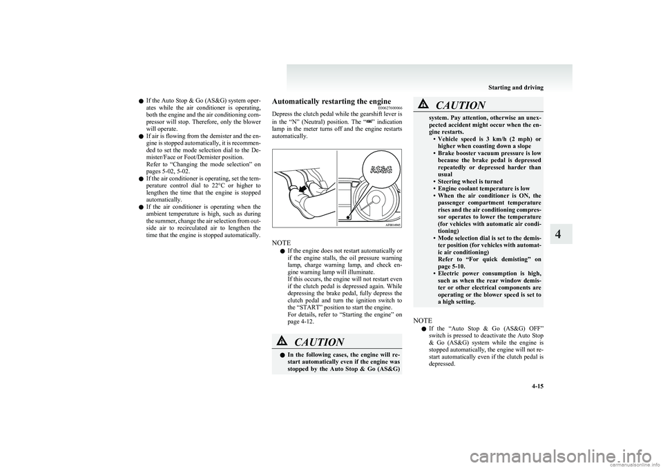
time that the engine is stopped automatically.Automatically restarting the engine E00627600066
Depress the clutch pedal while the gearshift lever is
in the “N” (Neutral) position. The “
” indication
lamp in the meter turns off and the engine restarts
automatically.
NOTE
l If the engine does not restart automatically or
if the engine stalls, the oil pressure warning
lamp, charge warning lamp, and check en-
gine warning lamp will illuminate.
If this occurs, the engine will not restart even
if the clutch pedal is depressed again. While
depressing the brake pedal, fully depress the
clutch pedal and turn the ignition switch to
the “START” position to start the engine.
For details, refer to “Starting the engine” on
page 4-12.
CAUTIONl In the following cases, the engine will re-
start automatically even if the engine was
stopped by the Auto Stop & Go (AS&G)CAUTIONsystem. Pay attention, otherwise an unex-
pected accident might occur when the en-
gine restarts. •Vehicle speed is 3 km/h (2 mph) or
higher when coasting down a slope
• Brake booster vacuum pressure is low
because the brake pedal is depressed
repeatedly or depressed harder than
usual
• Steering wheel is turned
• Engine coolant temperature is low
• When the air conditioner is ON, the
passenger compartment temperature
rises and the air conditioning compres-
sor operates to lower the temperature
(for vehicles with automatic air condi-
tioning)
• Mode selection dial is set to the demis-
ter position (for vehicles with automat-
ic air conditioning)
Refer to “For quick demisting” on
page 5-10.
• Electric power consumption is high,
such as when the rear window demis-
ter or other electrical components are
operating or the blower speed is set to
a high setting.
NOTE
l If the “Auto Stop & Go (AS&G) OFF”
switch is pressed to deactivate the Auto Stop
& Go (AS&G) system while the engine is
stopped automatically, the engine will not re-
start automatically even if the clutch pedal is
depressed.
Starting and driving
4-15
4
Page 131 of 274
Brake assist systemE00627000262
The brake assist system is a device assisting drivers
who cannot depress the brake pedal firmly when it
is necessary to do so (such as in emergency stop sit-
uations) and provides greater braking force.
If the brake pedal is depressed suddenly, the brakes
will be applied with more force than usual.CAUTIONl The brake assist system is not a device de-
signed to exercise braking force greater
than its capacity. Make sure to always
keep a sufficient distance between vehi-
cles in front of you without relying too
much on the brake assist system.
NOTE
l Once the brake assist system is operational,
it maintains great braking force even if the
brake pedal is lightly released.
To stop its operation, completely remove
your foot from the brake pedal.
l The brake assist system may become opera-
tional when the brake pedal is fully de-
pressed even if it has not been depressed sud-
denly.
l When the brake assist system is in use, you
may feel as if the depressed brake pedal is
soft, the pedal moves in small motions in con-
junction with the sound of the ABS opera-
tion, or the vehicle body and the steering
wheel vibrate. This occurs when the brake as-
sist system is operating normally and does
not indicate faulty operation. Continue to
firmly depress the brake pedal.
l You may hear an operation noise when the
brake pedal is depressed suddenly while sta-
tionary. This does not indicate a malfunction
and the brake assist system is operating nor-
mally.Anti-lock brake system (ABS) E00607100791
Environmental conditions can have an effect on
braking. During sudden braking when there is
snow, ice, oil, water etc. on the road surface, a skid
may occur. In this situation, steering control and
braking effectiveness is reduced and the stopping
distance is increased. The vehicle may also go into
an uncontrolled spin.
The ABS helps prevent the wheels from locking dur-
ing braking, thus maintaining directional stability,
ensuring controllability and providing optimum
braking force.
Driving hints l When using the anti-lock brake system (sud-
den braking), steering is slightly different
from normal driving conditions. Use the steer-
ing wheel carefully.
l Always maintain the same distance from the
vehicle in front of you as you would for a ve-
hicle not equipped with ABS.
Compared with vehicles not fitted with ABS,
your vehicle may require a longer stopping
distance in the following cases: • Driving on gravel or snow-covered roads.
• Driving with tyre chains installed.
• Driving on roads where the road surface
is pitted or has other differences in sur-
face height.
• Driving on bumpy roads or other poor driv-
ing surfaces.
Starting and driving
4-27
4