display MITSUBISHI COLT 2011 (in English) Service Manual
[x] Cancel search | Manufacturer: MITSUBISHI, Model Year: 2011, Model line: COLT, Model: MITSUBISHI COLT 2011Pages: 274, PDF Size: 17.88 MB
Page 176 of 274
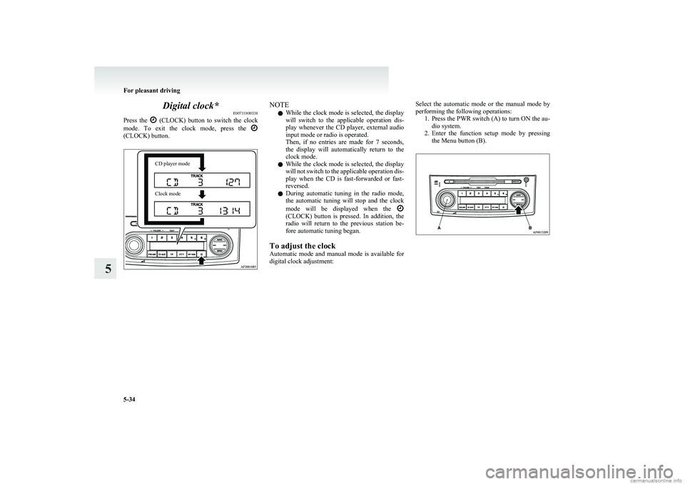
Digital clock*E00711800338
Press the
(CLOCK) button to switch the clock
mode. To exit the clock mode, press the
(CLOCK) button.
CD player modeClock modeNOTE
l While the clock mode is selected, the display
will switch to the applicable operation dis-
play whenever the CD player, external audio
input mode or radio is operated.
Then, if no entries are made for 7 seconds,
the display will automatically return to the
clock mode.
l While the clock mode is selected, the display
will not switch to the applicable operation dis-
play when the CD is fast-forwarded or fast-
reversed.
l During automatic tuning in the radio mode,
the automatic tuning will stop and the clock
mode will be displayed when the
(CLOCK) button is pressed. In addition, the
radio will return to the previous station be-
fore automatic tuning began.
To adjust the clock
Automatic mode and manual mode is available for
digital clock adjustment:
Select the automatic mode or the manual mode by
performing the following operations: 1.Press the PWR switch (A) to turn ON the au-
dio system.
2. Enter the function setup mode by pressing
the Menu button (B).
For pleasant driving
5-34
5
Page 177 of 274
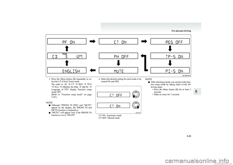
3.Press the Menu button (B) repeatedly to se-
lect the CT (Clock Time) mode.
The order is: AF
CT REG TP-S PI-S PHONE IN (PH) MUTE Language of PTY display Function setup
mode OFF
( Refer to “Function setup mode” on page
5-20.)
NOTE l Although “PHONE IN (PH)” and “MUTE”
appear on the display, the PHONE IN and
MUTE function is inoperative.
l “
MUTE” will appear only if the PHONE IN
function is set to “PH ON”.
4. Select the desired setting for each mode to be turned ON and OFF.
CT ON- Automatic mode
CT OFF- Manual mode
NOTE
l After selecting a mode, you can leave the func-
tion setup mode by taking either of the fol-
lowing steps: •Press the Menu button (B) for at least 2
seconds.
• Make no entry for 7 seconds.
For pleasant driving
5-35
5
Page 178 of 274
Automatic mode
The automatic mode can set the local time automat-
ically by using the signal from the local RDS sta-
tions. Refer to “Radio data system (RDS)” on page
5-17.
Manual mode
The manual mode is also available in case the “Au-
tomatic mode” shows the incorrect time when the
adjacent local RDS stations are located in a differ-
ent time zone. Refer to “Radio data system (RDS)”
on page 5-17.
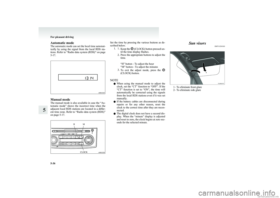
HMCLOCKSet the time by pressing the various buttons as de-
scribed below. 1. 1. Keep the
(CLOCK) button pressed un-
til the time display flashes.
2. Press the appropriate buttons to adjust the
time.
“H” button - To adjust the hour
“M” button - To adjust the minutes
3. To exit the adjust mode, press the
(CLOCK) button.
NOTE l When using the manual mode to adjust the
clock, set the “CT” function to “OFF”. If the
“CT” function is set to “ON”, the time will
automatically be corrected using the signals
from the local RDS stations even if it was set
manually.
l If the battery cables are disconnected during
repairs or for any other reason, reset the
clock to the correct time after they are recon-
nected.
l The digital clock does not have a second dis-
play. When the “minute” display is adjusted
and reset to zero, the clock begins at zero sec-
onds for the selected minute.
Sun visors E00711201010
1- To eliminate front glare
2- To eliminate side glare
For pleasant driving
5-36
5
Page 188 of 274
If the vehicle breaks downE00800101254
If the vehicle breaks down on the road, move it to
the shoulder and use the hazard warning flashers and/
or the warning triangle etc.
Refer to “Hazard warning flasher switch” on page
3-23.
If the engine stops/fails
Vehicle operation and control are affected if the en-
gine stops.
Before moving the vehicle to a safe area, be aware
of the following:
l The brake booster becomes inoperative and
the pedal effort will increase. Press down the
brake pedal harder than usual.
l Since the power steering system is no longer
operative, the steering wheel feels heavy
when turning it.Emergency starting E00800501900
If the engine cannot be started because the battery
is weak or dead, the battery from another vehicle
can be used with jumper cables to start the engine.WARNINGl To start the engine using jumper cables
connected to another vehicle, perform the
correct procedures according to the in-
struction below. Incorrect procedures
could result in a fire or explosion or dam-
age to the vehicles.
1. Get the vehicles close enough so the jumper
cables can reach, but be sure the vehicles
aren’t touching each other.
If they are, it could cause a ground connec-
tion you don’t want. The vehicle will not
start, and the bad grounding could damage
the electrical systems.
CAUTIONl Check the other vehicle. It must have a 12-
volt battery.
If the other system isn’t 12-volt, shorting
can damage both vehicles.2. You could be injured if the vehicles move.
Set the parking brake firmly on each vehicle.
Put an automatic transmission in “P”
(PARK) or a manual transmission and an au-
tomated manual transmission in “N” (Neu-
tral). With an automated manual transmis-
sion vehicle, confirm that “N” is shown by
the allshift indicator display. Turn off the ig-
nition switch.WARNINGl Turn off the ignition on both vehicles be-
forehand. Make sure that the cables or
your clothes cannot be caught by the fan
or drive belt. Personal injury could result.
NOTE
l Turn off all lamps, heater and other electrical
loads. This will avoid sparks and help save
both batteries.
3. Make sure battery electrolyte is at the proper
level. Refer to “Battery” on page 8-10.
WARNINGl If electrolyte fluid is not visible, or ap-
pears to be frozen, Do Not Attempt Jump
Starting!
A battery might rupture or explode if the
temperature is below the freezing point
or if it is not filled to the proper level.
For emergencies
6-02
6
Page 194 of 274
3.On vehicles with manual transmission, turn
the ignition key to the “LOCK” position,
move the gearshift lever to the “R” (Reverse)
position.
On vehicles with automated manual transmis-
sion, move the allshift lever to the “R” (Re-
verse) position, turn the ignition key to the
“LOCK” position.
With an automated manual transmission ve-
hicle, confirm that that “R” is shown by the
allshift indicator display.
4. Turn on the hazard warning flashers and set
up a warning triangle, flashing signal lamp,
etc., at an adequate distance from the vehi-
cle, and have all your passengers leave the ve-
hicle.
5. Take out the tyre sealant bottle and the com-
pressor.
NOTE l In cold conditions (when the ambient temper-
ature is 0 °C or lower). Warm the bottle in-
side the vehicle.
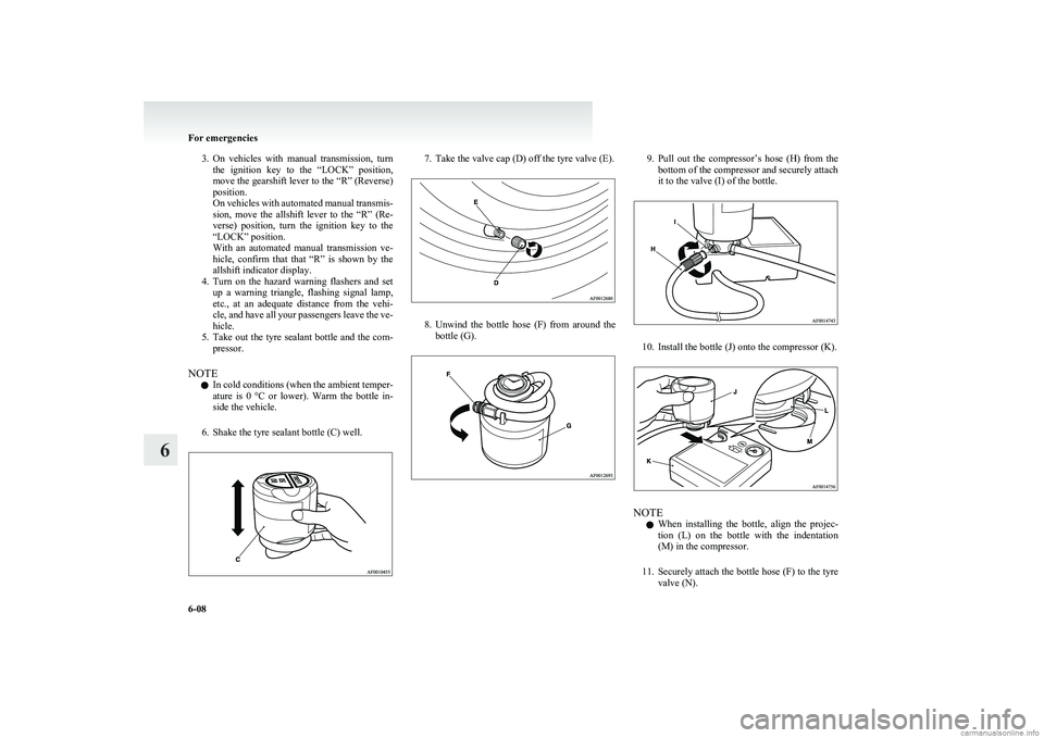
6. Shake the tyre sealant bottle (C) well.7. Take the valve cap (D) off the tyre valve (E).
8. Unwind the bottle hose (F) from around the
bottle (G).
9. Pull out the compressor’s hose (H) from the
bottom of the compressor and securely attach
it to the valve (I) of the bottle.
10. Install the bottle (J) onto the compressor (K).
NOTE
l When installing the bottle, align the projec-
tion (L) on the bottle with the indentation
(M) in the compressor.
11. Securely attach the bottle hose (F) to the tyre
valve (N).
For emergencies
6-08
6
Page 195 of 274
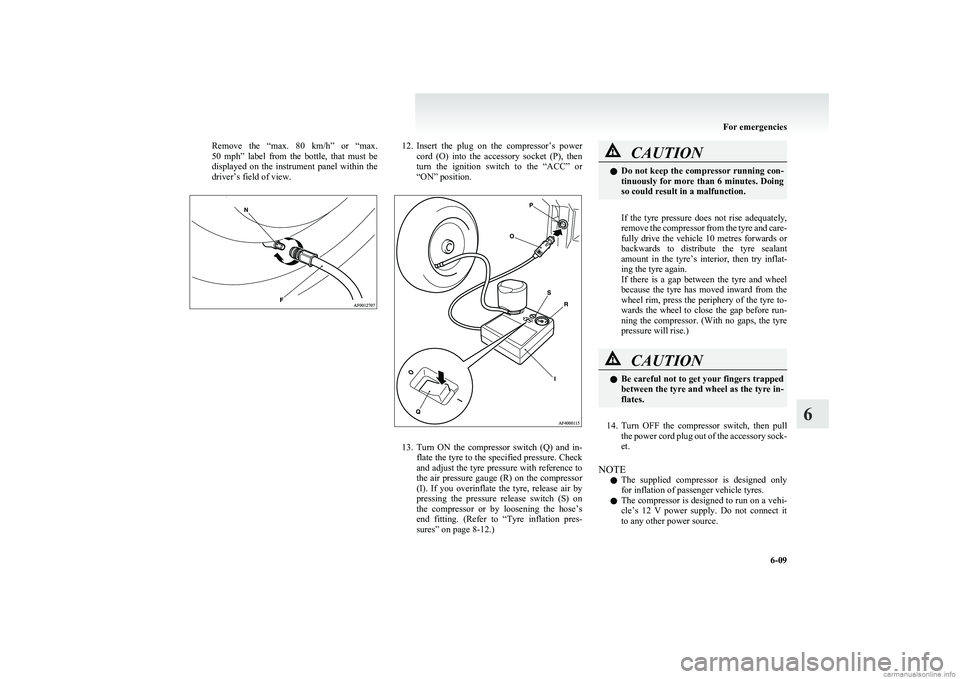
Remove the “max. 80 km/h” or “max.
50 mph ” label from the bottle, that must be
displayed on the instrument panel within the
driver’s field of view.12. Insert the plug on the compressor’s power
cord (O) into the accessory socket (P), then
turn the ignition switch to the “ACC” or
“ON” position.
13. Turn ON the compressor switch (Q) and in-
flate the tyre to the specified pressure. Check
and adjust the tyre pressure with reference to
the air pressure gauge (R) on the compressor
(I). If you overinflate the tyre, release air by
pressing the pressure release switch (S) on
the compressor or by loosening the hose’s
end fitting. (Refer to “Tyre inflation pres-
sures” on page 8-12.)
CAUTIONl Do not keep the compressor running con-
tinuously for more than 6 minutes. Doing
so could result in a malfunction.
If the tyre pressure does not rise adequately,
remove the compressor from the tyre and care-
fully drive the vehicle 10 metres forwards or
backwards to distribute the tyre sealant
amount in the tyre’s interior, then try inflat-
ing the tyre again.
If there is a gap between the tyre and wheel
because the tyre has moved inward from the
wheel rim, press the periphery of the tyre to-
wards the wheel to close the gap before run-
ning the compressor. (With no gaps, the tyre
pressure will rise.)
CAUTIONl Be careful not to get your fingers trapped
between the tyre and wheel as the tyre in-
flates.
14. Turn OFF the compressor switch, then pull
the power cord plug out of the accessory sock-
et.
NOTE l The supplied compressor is designed only
for inflation of passenger vehicle tyres.
l The compressor is designed to run on a vehi-
cle’s 12 V power supply. Do not connect it
to any other power source.
For emergencies
6-09
6
Page 196 of 274
lThe surface of the compressor will get hot
while the compressor is running. Do not
keep the compressor running continuously
for more than 6 minutes. After using the com-
pressor, wait for the compressor to cool be-
fore using it again.
l If the tyre pressure does not rise to the neces-
sary of at least 1.8 bar level within 5 mi-
nutes, the tyre may be so severely damaged
that the tyre sealant cannot be used to effect
an emergency repair. Please contact a
MITSUBISHI MOTORS Authorized Service
Point or another specialist in this event.
l Simply putting sealant and air into the tyre us-
ing the tyre repair kit does not seal the punc-
ture hole. Air will leak through the puncture
hole until the emergency repair procedure is
completed (through step 17 of these instruc-
tions).
15. When you have inflated the tyre to the speci-
fied pressure, stow the compressor and bottle
in the vehicle and promptly start driving the
vehicle so that the tire sealant can spread even-
ly in the tyre. Drive with great care. Do not
exceed a speed of 80 km/h (50 mph). Ob-
serve local speed limits.
Remove the “max. 80 km/h ” or “max.
50 mph ” label from the bottle, that must be
displayed on the instrument panel within the
driver’s field of view.CAUTIONl If you sense any abnormality while driv-
ing, stop the vehicle and contact a
MITSUBISHI MOTORS Authorized
Service Point or another specialist. Other-
wise the tyre pressure may drop before
the emergency repair procedure is com-
pleted, rendering the vehicle unsafe.
NOTE
l Driving faster than 80 km/h
(50 mph) can
make the vehicle vibrate.
16. After driving for 10 minutes, check the tyre
pressure using the air pressure gauge on the
compressor.
If the tyre pressure is not sufficient, inflate
the tyre to the specified pressure again and
drive the vehicle carefully without exceeding
a speed of 80 km/h (50 mph).
CAUTIONl If the tyre pressure is lower than the min-
imum permitted pressure (1.3 bar
{ 130 kPa}), the tyre cannot successfully
be repaired with the tyre sealant. Do not
drive the vehicle any further. Contact a
MITSUBISHI MOTORS Authorized
Service Point or another specialist.
17. After driving for 10 minutes, check the tyre
pressure using the air pressure gauge on the
compressor. (Refer to “Tyre inflation pres-
sures” on page 8-12.) If the tyre pressure
has apparently not dropped, the emergency re-
pair procedure is complete. You must still
not exceed a speed of 80 km/h (50 mph).
Observe local speed limits.
NOTE l If the tyre pressure has dropped below the
specified level when you check it at the end
of the repair procedure, do not drive the vehi-
cle any further. Contact a MITSUBISHI
MOTORS Authorized Service Point or anoth-
er specialist.
l In cold conditions (when the ambient temper-
ature is 0 °C or lower), the time and driving
distance necessary until completion of the re-
pair can be longer than in warmer conditions,
meaning that the tyre pressure can drop be-
low the specified level even when you have
inflated the tyre a second time and subsequent-
ly driven the vehicle. If this happens, inflate
the tyre to the specified pressure once more,
drive for about 10 minutes or 5 km (3 miles),
then check the tyre pressure again. If the tyre
pressure has again dropped below the speci-
fied level, stop driving the vehicle and con-
tact a MITSUBISHI MOTORS Authorized
Service Point or another specialist.
18. Then immediately drive with great care to a
MITSUBISHI MOTORS Authorized Service
Point or another specialist and have tyre re-
pair/replacement performed.
For emergencies
6-10
6
Page 198 of 274
Jacking up the vehicleE00801001218
1. Park the vehicle on level and stable ground.
2. Set the parking brake firmly.
3. On vehicles with manual transmission, turn
the ignition key to the “LOCK” position,
move the gearshift lever to the “R” (Reverse)
position.
On vehicles with automated manual transmis-
sion, move the allshift lever to the “R” (Re-
verse) position, turn the ignition key to the
“LOCK” position.
With an automated manual transmission ve-
hicle, confirm that there is a “A” or “1” in
the allshift indicator display.
4. Turn on the hazard warning flashers and set
up a warning triangle, flashing signal lamp,
etc., at an adequate distance from the vehi-
cle, and have all your passengers leave the ve-
hicle.
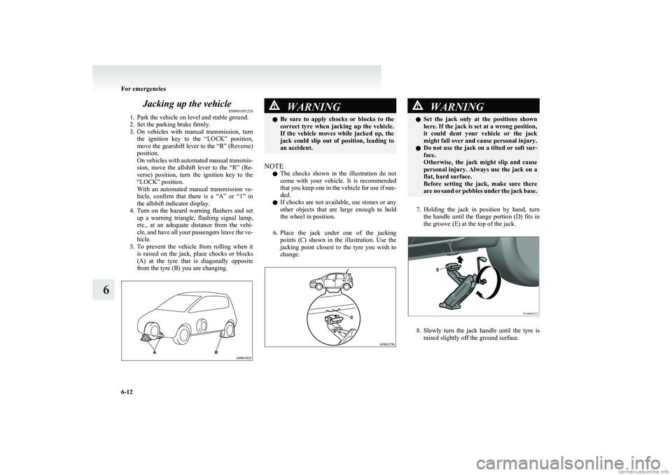
5. To prevent the vehicle from rolling when it
is raised on the jack, place chocks or blocks
(A) at the tyre that is diagonally opposite
from the tyre (B) you are changing.WARNINGl Be sure to apply chocks or blocks to the
correct tyre when jacking up the vehicle.
If the vehicle moves while jacked up, the
jack could slip out of position, leading to
an accident.
NOTE
l The chocks shown in the illustration do not
come with your vehicle. It is recommended
that you keep one in the vehicle for use if nee-
ded.
l If chocks are not available, use stones or any
other objects that are large enough to hold
the wheel in position.
6. Place the jack under one of the jacking
points (C) shown in the illustration. Use the
jacking point closest to the tyre you wish to
change.
WARNINGl Set the jack only at the positions shown
here. If the jack is set at a wrong position,
it could dent your vehicle or the jack
might fall over and cause personal injury.
l Do not use the jack on a tilted or soft sur-
face.
Otherwise, the jack might slip and cause
personal injury. Always use the jack on a
flat, hard surface.
Before setting the jack, make sure there
are no sand or pebbles under the jack base.
7. Holding the jack in position by hand, turn
the handle until the flange portion (D) fits in
the groove (E) at the top of the jack.
8. Slowly turn the jack handle until the tyre is
raised slightly off the ground surface.
For emergencies
6-12
6
Page 201 of 274
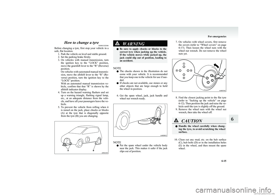
How to change a tyreE00801202086
Before changing a tyre, first stop your vehicle in a
safe, flat location. 1. Park the vehicle on level and stable ground.
2. Set the parking brake firmly.
3. On vehicles with manual transmission, turn
the ignition key to the “LOCK” position,
move the gearshift lever to the “R” (Reverse)
position.
On vehicles with automated manual transmis-
sion, move the allshift lever to the “R” (Re-
verse) position, turn the ignition key to the
“LOCK” position.
With an automated manual transmission ve-
hicle, confirm that that “R” is shown by the
allshift indicator display.
4. Turn on the hazard warning flashers and set
up a warning triangle, flashing signal lamp,
etc., at an adequate distance from the vehi-
cle, and have all your passengers leave the ve-
hicle.
5. To prevent the vehicle from rolling when it
is raised on the jack, place chocks or blocks
(A) at the tyre that is diagonally opposite
from the tyre (B) you are changing.WARNINGl Be sure to apply chocks or blocks to the
correct tyre when jacking up the vehicle.
If the vehicle moves while jacked up, the
jack could slip out of position, leading to
an accident.
NOTE
l The chocks shown in the illustration do not
come with your vehicle. It is recommended
that you keep one in the vehicle for use if nee-
ded.
l If chocks are not available, use stones or any
other objects that are large enough to hold
the wheel in position.
6. Get the spare wheel, jack, jack handle and
wheel nut wrench ready.
NOTE
l Put the spare wheel under the vehicle body
near the jack. This makes it safer if the jack
slips out of position.
7. On vehicles with wheel covers, first remove
the covers (refer to “Wheel covers” on page
6-17 ). Then loosen the wheel nuts with the
wheel nut wrench. Do not remove the wheel
nuts yet.
8. Find the closest jacking point to the flat tyre
(refer to “Jacking up the vehicle” on page
6-12 ). Then position the jack and raise the ve-
hicle until the tyre is slightly off the ground.
9. Remove the wheel nuts with the wheel nut
wrench, then take the wheel off.
CAUTIONl Handle the wheel carefully when chang-
ing the tyre, to avoid scratching the wheel
surface.
10. Clean out any mud, etc. on the hub surface
(C), hub bolts (D) or in the installation holes
(E) in the wheel, and then mount the spare
wheel.
For emergencies
6-15
6
Page 205 of 274
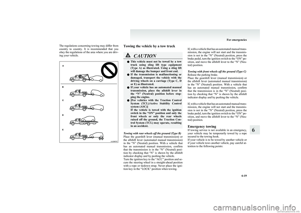
The regulations concerning towing may differ from
country to country. It is recommended that you
obey the regulations of the area where you are driv-
ing your vehicle.Towing the vehicle by a tow truckCAUTIONl This vehicle must not be towed by a tow
truck using sling lift type equipment
(Type A) as illustrated. Using a sling lift
will damage the bumper and front end.
l If the transmission is malfunctioning or
damaged, transport the vehicle with the
driving wheels on a carriage (Type C, D
or E) as illustrated.
l If your vehicle has an automated manual
transmission, place the allshift lever in
the “N” (Neutral) position before stop-
ping the engine.
l [
For vehicles with the Traction Control
System (TCL)/Active Stability Control
system (ASC)]
If the vehicle is towed with the ignition
switch in the “ON” position and only the
front wheels or only the rear wheels
raised off the ground, the Traction Con-
trol System (TCL) may operate, resulting
in an accident.
Towing with rear wheels off the ground (Type B)
Place the gearshift lever (manual transmission) or
the allshift lever (automated manual transmission)
in the “N” (Neutral) position. With a vehicle that
has an automated manual transmission, confirm
that the transmission is in the “N” (Neutral) posi-
tion by checking that “N” is shown by the allshift
indicator display and by pushing the vehicle.
Turn the ignition key to the “ACC” position and se-
cure the steering wheel in a straight-ahead position
with a rope or tiedown strap. Never place the igni-
tion key in the “LOCK” position when towing.
If, with a vehicle that has an automated manual trans-
mission, the engine will not start and the transmis-
sion is not in the “N” (Neutral) position, press the
brake pedal, turn the ignition switch to the “ON” po-
sition, and move the allshift lever to the “N” (Neu-
tral) position.
Towing with front wheels off the ground (Type C)
Release the parking brake.
Place the gearshift lever (manual transmission) or
the allshift lever (automated manual transmission)
in the “N” (Neutral) position. With a vehicle that
has an automated manual transmission, confirm
that the transmission is in the “N” (Neutral) posi-
tion by checking that “N” is shown by the allshift
indicator display and by pushing the vehicle.
If, with a vehicle that has an automated manual trans-
mission, the engine will not start and the transmis-
sion is not in the “N” (Neutral) position, press the
brake pedal, turn the ignition switch to the “ON” po-
sition, and move the allshift lever to the “N” (Neu-
tral) position.
Emergency towing
If towing service is not available in an emergency,
your vehicle may be temporarily towed by a rope
secured to the towing hook.
If your vehicle is to be towed by another vehicle or
if your vehicle tows another vehicle, pay careful at-
tention to the following points:
For emergencies
6-19
6