cooling MITSUBISHI DIAMANTE 1900 Workshop Manual
[x] Cancel search | Manufacturer: MITSUBISHI, Model Year: 1900, Model line: DIAMANTE, Model: MITSUBISHI DIAMANTE 1900Pages: 408, PDF Size: 71.03 MB
Page 244 of 408
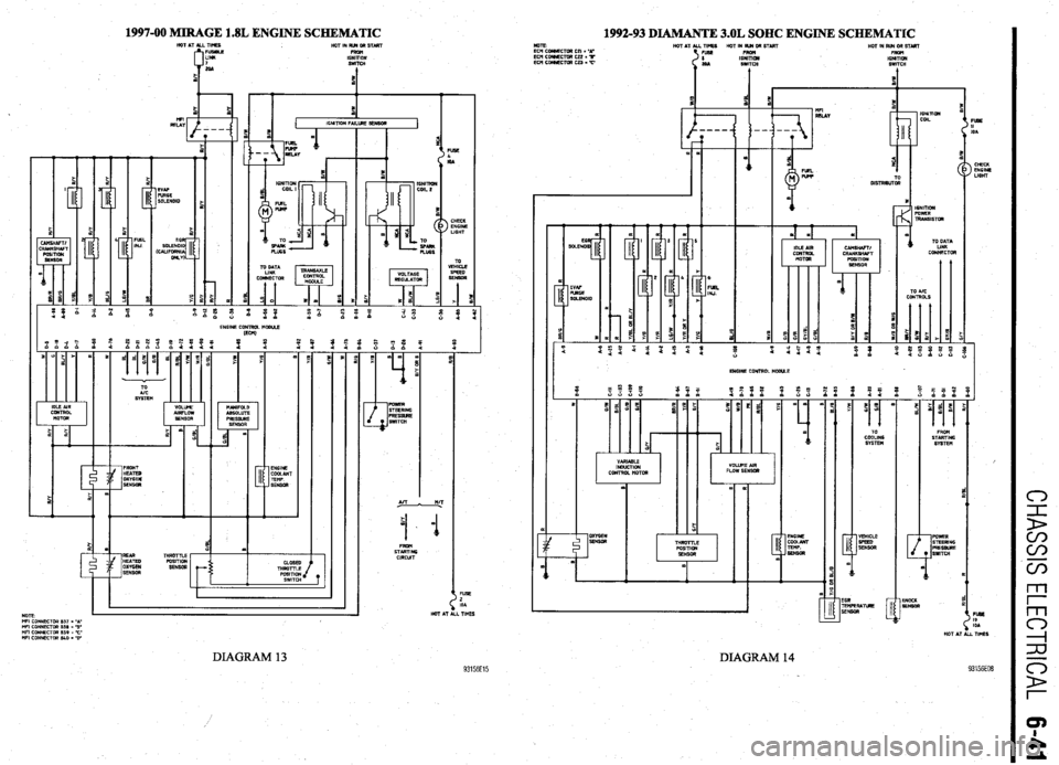
1997-00 MIRAGE 1.8L ENGINE SCHEMATIC
1992-93 DIAMANTE 3.OL SOHC ENGINE SCHEMATIC NOTE
HOT AT ML TIHGS
HOT IN R&S4 OR STbRT
HOT IM RUN OR START
ECM CGNNECTOR CZI = ‘4.
FUSS FROn
ECM COmECTOR CL2 = w
I IGNITIW
Et24 COtWECTOR CZ3 = ‘IT
zG4 SWITCH FROM
IGNlnON
SWITCH
4 HOT AT UL TIMES
HOT IN RiN GR START
FUSIRLE
FRW
LINK
IGNITION
:04 SWITCH
5
1
IGHlnON FAiLUlE SENSOR
FUSE
b
IO4
CHECK
ENGINE
LIGHT
TO
VEHICLG
ENGINE CONTROL MO4M.E
IECH)
II
ENGINE CONTROL MWUE
, 1 TO
COOLING
SYSTlw4
EGR
TEHFRR4TLtGE
SENSOR 1 POWER
STEERIMG
cI>
72
D
cn
c&n
.-
CD NT A NIT
.
5 (I)
I 4 FROM
STARTING
CIRCUT
HOT AT F!u3swE SWITCH
KNOCK
SENM
FLsC
I9
104 POSITION 6
SWITCH
FL&G
2
IOA
TIMES
hl
c3
-i
zu MFI CONNECTOR 8.37 = ‘4.
MFI CONNECTOR 811 - 3’
Hfl CONNECTOR 6.59 = ‘C’
WI CONNECTOR Sk0 g ‘D-
93156E15 DIAGRAM 13
DIAGRAM 14
Page 246 of 408
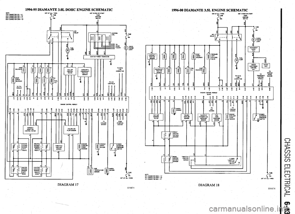
1994-95 DIAMANTE 3.OL DOHC ENGINE SCHEMATIC
1996-00 DIAMANTE 3SL ENGINE SCHEMATIC HOT AT ALL TIMES HOTINRUNORSTART
39 FLBG FRan
IGNITICU NOTE:
HOT AT ML TIMES HOT IN RUN OR START
ECH CONNECTOR CZI . *A’
ECN CONNECTOR C22 * 8’ FUSG FROn
ECN CONNECTOR CZ3 = Kc”
:9A IGNITION
ECH CONNECTOR Cl05 * .O- SWITCH
t CH
TO DATh
LIM
CCNNECTOR TO DATA
LINK
CONNECTOR
- TO
VEHICLE
TR&LE SPEED
SENSOR
TO AIC
CONTROLS
HOT AT TO
SYZ&
NANIFOLO FUEL
DIFFERENTIAL TANK
PRESSURE PRESSURE
SENSOR SENSOR
$. = TO
COOLING
SYSTEM
$5” z
: $g$F
m m 0
1 1
TO FROM
COOLING STARTING
SYSTEM
SYm3
*
HOTP: FUSE
I9
IQA
TIMES I
NOTE:
BFI CONPECTOR RI05 = ‘A’
HFI CONNECTOR BID9 = ‘8’
DIAGRAM 18 93156E16 DIAGRAM 17 93156Ell
Page 338 of 408
9-2 BRAKES
Hydraulic systems are used to actuate the brakes
of all modern automobiles. The system transports the
power required to force the frictional surfaces of the
braking system together from the pedal to the indi-
vidual brake units at each wheel. A hydraulic system
is used for two reasons.
First, fluid under pressure can be carried to all
parts of an automobile by small pipes and flexible
hoses without taking up a significant amount of room
or posing routing problems.
Second, a great mechanical advantage can be
given to the brake pedal end of the system, and the
foot pressure required to actuate the brakes can be
reduced by making the surface area of the master
cylinder pistons smaller than that of any of the pis-
tons in the wheel cylinders or calipers.
The master cylinder consists of a fluid reservoir
along with a double cylinder and piston assembly.
Double type master cylinders are designed to sepa-
rate the front and rear braking systems hydraulically
in case of a leak. The master cylinder converts me-
chanical motion from the pedal into hydraulic pres-
sure within the lines. This pressure is translated back
into mechanical motion at the wheels by either the
wheel cylinder (drum brakes) or the caliper (disc
brakes).
Steel lines carry the brake fluid to a point on the
vehicle’s frame near each of the vehicle’s wheels. The
fluid is then carried to the calipers and wheel cylin-
ders by flexible tubes in order to allow for suspen-
sion and steering movements.
In drum brake systems, each wheel cylinder con-
tains two pistons, one at either end, which push out-
ward in opposite directions and force the brake shoe
into contact with the drum.
In disc brake systems, the cylinders are part of the
calipers. At least one cylinder in each caliper is used
to force the brake pads against the disc.
All pistons employ some type of seal, usually
made of rubber, to minimize fluid leakage. A rubber
dust boot seals the outer end of the cylinder against
dust and dirt. The boot fits around the outer end of
the piston on disc brake calipers, and around the
brake actuating rod on wheel cylinders.
The hydraulic system operates as follows: When at
rest, the entire system, from the piston(s) in the mas-
ter cylinder to those in the wheel cylinders or
calipers, is full of brake fluid. Upon application of the
brake pedal, fluid trapped in front of the master cylin-
der piston(s) is forced through the lines to the wheel
cylinders. Here, it forces the pistons outward, in the
case of drum brakes, and inward toward the disc, in
the case of disc brakes. The motion of the pistons is
opposed by return springs mounted outside the
cylinders in drum brakes, and by spring seals, in disc
brakes.
Upon release of the brake pedal, a spring located
inside the master cylinder immediately returns the
master cylinder pistons to the normal position. The
pistons contain check valves and the master cylinder
I
has compensating ports drilled in it. These are un-
covered as the pistons reach their normal position.
The piston check valves allow fluid to flow toward the
wheel cylinders or calipers as the pistons withdraw.
Then, as the return springs force the brake pads or
shoes into the released position, the excess fluid
reservoir through the compensating ports. It is during the time the pedal is in the released position that any
fluid that has leaked out of the system will be re-
placed through the compensating ports.
Dual circuit master cylinders employ two pistons,
located one behind the other, in the same cylinder.
The primary piston is actuated directly by mechanical
linkage from the brake pedal through the power
booster. The secondary piston is actuated by fluid
trapped between the two pistons. If a leak develops in
front of the secondary piston, it moves forward until it
bottoms against the front of the master cylinder, and
the fluid trapped between the pistons will operate the
rear brakes. If the rear brakes develop a leak, the pri-
mary piston will move forward until direct contact
with the secondary piston takes place, and it will
force the secondary piston to actuate the front brakes.
In either case, the brake pedal moves farther when the
brakes are applied, and less braking power is avail-
able.
All dual circuit systems use a switch to warn the
driver when only half of the brake system is opera-
tional. This switch is usually located in a valve body
which is mounted on the firewall or the frame below
the master cylinder. A hydraulic piston receives pres-
sure from both circuits, each circuits pressure being
applied to one end of the piston. When the pressures
are in balance, the piston remains stationary. When
one circuit has a leak, however, the greater pressure
in that circuit during application of the brakes will
push the piston to one side, closing the switch and
activating the brake warning light.
In disc brake systems, this valve body also con-
tains a metering valve and, in some cases, a propor-
tioning valve. The metering valve keeps pressure
from traveling to the disc brakes on the front wheels
until the brake shoes on the rear wheels have con-
tacted the drums, ensuring that the front brakes will
never be used alone. The proportioning valve con-
trols the pressure to the rear brakes to lessen the
chance of rear wheel lock-up during very hard brak-
ing.
Warning lights may be tested by depressing the
brake pedal and holding it while opening one of the
wheel cylinder bleeder screws. If this does not cause
the light to go on, substitute a new lamp, make conti-
nuity checks, and, finally, replace the switch as nec-
essary.
The hydraulic system may
be checked for leaks by applying pressure to the pedal gradually and steadily.
If the pedal sinks very slowly to the floor, the system
has a leak. This is not to be confused with a springy
or spongy feel due to the compression of air within
the lines. If the system leaks, there will be a gradual
change in the position of the pedal with a constant
pressure.
Check for leaks along all lines and at wheel cylin-
ders. If no external leaks are apparent, the problem is
inside the master cylinder,
DISC BRAKES
Instead of the traditional expanding brakes that
press outward against a circular drum, disc brake
systems utilize a disc (rotor) with brake pads posi-
tioned on either side of it. An easily-seen analogy is
the hand brake arrangement on a bicycle. The pads
squeeze onto the rim of the bike wheel, slowing its
motion. Automobile disc brakes use the identical principle but apply the braking effort to a separate
disc instead of the wheel.
The disc (rotor) is a casting, usually equipped with
cooling fins between the two braking surfaces. This
enables air to circulate between the braking surfaces
making them less sensitive to heat buildup and more
resistant to fade. Dirt and water do not drastically af-
fect braking action since contaminants are thrown off
by the centrifugal action of the rotor or scraped off
the by the pads. Also, the equal clamping action of
the two brake pads tends to ensure uniform, straight
line stops. Disc brakes are inherently self-adjusting.
There are three general types of disc brake:
1. A fixed caliper.
2. A floating caliper.
3. A sliding caliper.
The fixed caliper design uses two pistons
mounted on either side of the rotor (in each side of
the caliper). The caliper is mounted rigidly and does
not move.
The sliding and floating designs are quite similar.
In fact, these two types are often lumped together. In
both designs, the pad on the inside of the rotor is
moved into contact with the rotor by hydraulic force.
The caliper, which is not held in a fixed position,
moves slightly, bringing the outside pad into contact
with the rotor. There are various methods of attaching
floating calipers. Some pivot at the bottom or top,
and some slide on mounting bolts. In any event, the
end result is the same.
DRUM BRAKES
Drum brakes employ two brake shoes mounted on
a stationary backing plate. These shoes are posi-
tioned inside a circular drum which rotates with the
wheel assembly. The shoes are held in place by
springs. This allows them to slide toward the drums
(when they are applied) while keeping the linings and
drums in alignment. The shoes are actuated by a
wheel cylinder which is mounted at the top of the
backing plate. When the brakes are applied, hydraulic
pressure forces the wheel cylinder’s actuating links
outward. Since these links bear directly against the
top of the brake shoes, the tops of the shoes are then
forced against the inner side of the drum. This action
forces the bottoms of the two shoes to contact the
brake drum by rotating the entire assembly slightly
(known as servo action). When pressure within the
wheel cylinder is relaxed, return springs pull the
shoes back away from the drum.
Most modern drum brakes are designed to self-
adjust themselves during application when the vehi-
cle is moving in reverse. This motion causes both
shoes to rotate very slightly with the drum, rocking
an adjusting lever, thereby causing rotation of the ad-
justing screw. Some drum brake systems are de-
signed to self-adjust during application whenever the
brakes are applied. This on-board adjustment system
reduces the need for maintenance adjustments and
keeps both the brake function and pedal feel satisfac-
tory.
POWER BOOSTERS
Virtually all modern vehicles use a vacuum as-
sisted power brake system to multiply the braking
force and reduce pedal effort. Since vacuum is always
available when the engine is operating, the system is
Page 383 of 408

TROUBLESHOOTING INDEX 11-2
SECTION 1: ENGINE 11-2
SECTION 2: DRIVE TRAIN
11-3
SECTION 3:BRAKESYSTEM 11-3
SECTION 4:WHEELS,TIRES, STEERING,
AND SUSPENSION II-4
SECTION 5: ELECTRICAL
ACCESSORIES II-4
SECTION 6:lNSTRUMENTSAND
GAUGES II-5
SECTION 7:CLlMATE CONTROL II-5
DIAGNOSTIC PROCEDURES II-6
SECTION 1: ENGINE II-6
ENGINE STARTING PROBLEMS II-6
ENGINE RUNNING CONDITIONS II-7
ENGINE NOISES,ODORSAND
VIBRATIONS II-8
ENGINE ELECTRICALSYSTEM 11-8
ENGINE COOLING SYSTEM II-8
ENGINE EXHAUSTSYSTEM II-9
SECTION 2: DRIVE TRAIN
II-9
AUTOMATIC TRANSMISSION II-9
MANUALTRANSMISSION II-10
CLUTCH II-10
DIFFERENTIAL AND FINAL
DRIVE II-10
TRANSFER ASSEMBLY II-10
DRIVESHAFT II-10
AXLES II-II
OTHER DRIVE TRAIN
CONDITIONS II-II
SECTION 3:BRAKE SYSTEM II-II
BRAKESYSTEM
TROUBLESHOOTING II-II
SECTION 4:WHEELS, TIRES, STEERING
AND SUSPENSION II-12
WHEELSAND WHEEL
BEARINGS II-12
TIRES II-12
STEERING II-12
SUSPENSION II-12
DRIVING NOISES AND
VIBRATIONS II-13
SECTION 5:ELECTRlCAL
ACCESSORIES II-13 -
HEADLIGHTS II-13
TAIL, RUNNING AND SIDE MARKER
LIGHTS II-13
INTERIOR LIGHTS II-14
BRAKE LIGHTS II-14
WARNING LIGHTS II-14
TURN SlGNALAND4-WAYHAZARD
LIGHTS II-15
WINDSHIELD WIPERS II-15
SECTION 6:lNSTRUMENTSAND
GAUGUES II-15
I
SPEEDOMETER(CABLE
OPERATED) II-15
SPEEDOMETER(ELECTRONICALLY
OPERATED) II-16
FUEL,TEMPERATUREAkJD OIL
PRESSURE GAUGES II-16 SECTION 7:CLlMATECON
AIR CONDITIONER ll-
HEATER II-16 TR(
-16 IL II-16
Page 390 of 408
11-8 TROUBLESHOOTING
Ignition systems may be controlled by, or linked to, the engine fuel management sys-
tem. Similar to the fuel injection system, these ignition systems rely on electronic sen-
sors for information to determine the optimum ignition timing for a given engine speed
and load. Some ignition systems no longer allow the ignition timing to be adjusted.
Feedback from low voltage electrical sensors provide information to the control unit to
determine the amount of ignition advance. On these systems, if a failure occurs the failed
component must be replaced. Before replacing suspected failed electrical components,
carefully inspect the wiring and electrical connectors to the related components. Make
sure the electrical connectors are fully connected, clean and not physically damaged. If
necessary, clean the electrical contacts using electrical contact cleaner. The use of clean-
ing agents not specifically designed for electrical contacts should be avoided, as they
could leave a surface film or damage the insulation of the wiring.
1. Engine makes a knocking or pinging noise when accelerating
a. Check the octane rating of the fuel being used. Depending on the type of driving or
driving conditions, it may be necessary to use a higher octane fuel.
b. Verify the ignition system settings and operation. Improperly adjusted ignition timing
or a failed component, such as a knock sensor, may cause the ignition timing to ad-
vance excessively or prematurely. Check the ignition system operation and adjust, or
replace components as needed.
c. Check the spark plug gap, heat range and condition. If the vehicle is operated in se-
vere operating conditions or at continuous high speeds, use a colder heat range spark
plug. Adjust the spark plug gap to the manufacturer’s recommended specification and
replace worn or damaged spark plugs.
2. Sfarter motor grinds when used
a. Examine the starter pinion gear and the engine ring gear for damage, and replace dam-
aged parts.
b. Check the starter mounting bolts and housing. If the housing is cracked or damaged
replace the starter motor and check the mounting bolts for tightness.
3. Engine makes a screeching noise
a. Check the accessory drive belts for looseness and adjust as necessary.
b. Check the accessory drive belt tensioners for seizing or excessive bearing noises and
replace if loose, binding, or excessively noisy.
c. Check for a seizing water pump. The pump may not be leaking; however, the bearing
may be faulty or the impeller loose and jammed. Replace the water pump.
4. Engine makes a growling noise
a. Check for a loose or failing water pump. Replace the pump and engine coolant.
b. Check the accessory drive belt tensioners for excessive bearing noises and replace if
loose or excessively noisy.
5. Engine makes a ticking or tapping noise
a. On vehicles with hydraulic lash adjusters, check for low or dirty engine oil and top off
or replace the engine oil and filter.
b. On vehicles with hydraulic lash adjusters, check for collapsed lifters and replace failed
components.
c. On vehicles with hydraulic lash adjusters, check for low oil pressure caused by a re-
stricted oil filter, worn engine oil pump, or oil pressure relief valve.
d. On vehicles with manually adjusted valves, check for excessive valve clearance or
worn valve train parts. Adjust the valves to specification or replace worn and defective
parts.
e. Check for a loose or improperly tensioned timing belt or timing chain and adjust or re-
place parts as necessary.
f. Check for a bent or sticking exhaust or intake valve. Remove the engine cylinder head
to access and replace.
6. Engine makes a heavy knocking noise
a. Check for a loose crankshaft pulley or flywheel; replace and torque the mounting
bolt(s) to specification.
b. Check for a bent connecting rod caused by a hydro-lock condition. Engine disassem-
bly is necessary to inspect for damaged and needed replacement parts.
c. Check for excessive engine rod bearing wear or damage. This condition is also asso-
ciated with low engine oil pressure and will require engine disassembly to inspect for
damaged and needed replacement parts,
7. Vehicle has a fuel odor when driven ’ a. Check the fuel gauge level. If the fuel gauge registers full, it is possible that the odor is
caused by being filled beyond capacity, or some spillage occurred during refueling.
The odor should clear after driving an hour, or twenty miles, allowing the vapor canis-
ter to purge.
b. Check the fuel filler cap for looseness or seepage. Check the cap tightness and, if
loose, properly secure. If seepage is noted, replace the filler cap.
c. Check for loose hose clamps, cracked or damaged fuel delivery and return lines, or
leaking components or seals, and replace or repair as necessary. d. Check the vehicle’s fuel economy. If fuel consumption has increased due to a failed
component, or if the fuel is not properly ignited due to an ignition related failure, the
catalytic converter may become contaminated. This condition may also trigger the
check engine warning light. Check the spark plugs for a dark, rich condition or verify
the condition by testing the vehicle’s emissions. Replace fuel fouled spark plugs, and
test and replace failed components as necessary.
5. Vehicle has a rotten egg odor when driven
a. Check for a leaking intake gasket or vacuum leak causing a lean running condition. A
lean mixture may result in increased exhaust temperatures, causing the catalytic con-
verter to run hotter than normal. This condition may also trigger the check engine
warning light. Check and repair the vacuum leaks as necessary.
b. Check the vehicle’s alternator and battery condition. If the alternator is overcharging,
the battery electrolyte can be boiled from the battery, and the battery casing may begin
to crack, swell or bulge, damaging or shorting the battery internally. If this has oc-
curred, neutralize the battery mounting area with a suitable baking soda and water
mixture or equivalent, and replace the alternator or voltage regulator. Inspect, service,
and load test the battery, and replace if necessary.
9. Vehicle has a sweet odor when driven
a. Check for an engine coolant leak caused by a seeping radiator cap, loose hose clamp,
weeping cooling system seal, gasket or cooling system hose and replace or repair as
needed.
b. Check for a coolant leak from the radiator, coolant reservoir, heater control valve or
under the dashboard from the heater core, and replace the failed part as necessary.
c. Check the engine’s exhaust for white smoke in addition to a sweet odor. The presence
of white, steamy smoke with a sweet odor indicates coolant leaking into the combus-
tion chamber. Possible causes include a failed head gasket, cracked engine block or
cylinder head. Other symptoms of this condition include a white paste build-up on the
inside of the oil filler cap, and softened, deformed or bulging radiator hoses.
19. Engine vibraies when idling
a. Check for loose, collapsed, or damaged engine or transmission mounts and repair or
replace as necessary.
b. Check for loose or damaged engine covers or shields and secure or replace as neces-
sary.
11. Engine vibrates during acceleration
a. Check for missing, loose or damaged exhaust system hangers and mounts; replace or
repair as necessary.
b. Check the exhaust system routing and fit for adequate clearance or potential rubbing;
repair or adjust as necessary.
7. Battery goes dead while driving
a. Check the battery condition. Replace the battery if the battery will not hold a charge or
fails a battery load test. If the battery loses fluid while driving, check for an overcharg-
ing condition. If the alternator is overcharging, replace the alternator or voltage regula-
tor. (A voltage regulator is typically built into the alternator, necessitating alternator re-
placement or overhaul.)
b. Check the battery cable condition. Clean or replace corroded cables and clean the bat-
tery terminals.
c. Check the alternator and voltage regulator operation. If the charging system is over or
undercharging, replace the alternator or voltage regulator, or both.
d. Inspect the wiring and wire connectors at the alternator for looseness, a missing .
ground or defective terminal, and repair as necessary.
e. Inspect the alternator drive belt tension, tensioners and condition. Properly tension the
drive belt, replace weak or broken tensioners, and replace the drive belt if worn or
cracked.
2. Battery goes dead overnight
a. Check the battery condition. Replace the battery if the battery will not hold a charge or
fails a battery load test.
b. Check for a voltage draw, such as a trunk light, interior light or glove box light staying
on. Check light switch position and operation, and replace if defective.
c. Check the alternator for an internally failed diode, and replace the alternator if defec-
tive.
1. Engine overheats
a. Check the coolant level. Set the heater temperature to full hot and check for internal air
pockets, bleed the cooling system and inspect for leakage. Top off the cooling system
with the correct coolant mixture.
b. Pressure test the cooling system and radiator cap for leaks. Check for seepage caused
by loose hose clamps, failed coolant hoses, and cooling system components such as
the heater control valve, heater core, radiator, radiator cap, and water pump. Replace
defective parts and fill the cooling system with the recommended coolant mixture.
Page 391 of 408
TROUBLESHOOTING 11-9
c. On vehicles with electrically controlled cooling fans, check the cooling fan operation.
Check for blown fuses or defective fan motors, temperature sensors and relays, and
replace failed components.
d. Check for a coolant leak caused by a failed head gasket, or a porous water jacket cast-
ing in the cylinder head or engine block. Replace defective parts as necessary.
e. Check for an internally restricted radiator. Flush the radiator or replace if the blockage
is too severe for flushing.
f. Check for a damaged water pump. If coolant circulation is poor, check for a loose wa-
ter pump impeller. If the impeller is loose, replace the water pump.
2. Engine loses coolant
a. Pressure test the cooling system and radiator cap for leaks. Check for seepage caused
by loose hose clamps, failed coolant hoses, and cooling system components such as
the heater control valve, heater core, radiator, radiator cap, and water pump. Replace
defective parts and fill the cooling system with the recommended coolant mixture.
b. Check for a coolant leak caused by a failed head gasket, or a porous water jacket cast-
ing in the cylinder head or engine block. Replace defective parts as necessary.
3. Engine temperature remains co/d when driving
a. Check the thermostat operation. Replace the thermostat if it sticks in the open posi-
tion.
b. On vehicles with electrically controlled cooling fans, check the cooling fan operation.
Check for defective temperature sensors and stuck relays, and replace failed compo-
nents.
c. Check temperature gauge operation if equipped to verify proper operation of the
gauge. Check the sensors and wiring for defects, and repair or replace defective com-
ponents.
4. Engine runs hot
a. Check for an internally restricted radiator. Flush the radiator or replace if the blockage
is too severe for flushing.
b. Check for a loose or slipping water pump drive belt. Inspect the drive belt condition.
Replace the belt if brittle, cracked or damaged. Check the pulley condition and prop-
erly tension the belt.
c. Check the cooling fan operation. Replace defective fan motors, sensors or relays as
necessary.
d. Check temperature gauge operation if equipped to verify proper operation of the
gauge. Check the sensors and wiring for defects, and repair or replace defective com-
ponents.
e. Check the coolant level. Set the heater temperature to full hot, check for internal air
pockets, bleed the cooling system and inspect for leakage. Top off the cooling system
with the correct coolant mixture. Once the engine is cool, recheck the fluid level and
top off as needed.
NOTE: The engine cooling system can also be affected by an engine’s me-
chanical condition. A failed head gasket or a porous casting in the engine
block or cylinder head could cause a loss of coolant and result in engine
overheating.
Some cooling systems rely on electrically driven cooling fans to cool the radiator and
use electrical temperature sensors and relays to operate the cooling fan. When diagnos-
ing these systems, check for blown fuses, damaged wires and verify that the electrical
connections are fully connected, clean and not physically damaged. If necessary, clean
the electrical contacts using electrical contact cleaner. The use of cleaning igents not specifically designed for electrical contacts could leave a film or damage the insulation of
the wiring.
1. Exhaust rattles at idle speed
a. Check the engine and transmission mounts and replace mounts showing signs of
damage or wear.
b. Check the exhaust hangers, brackets and mounts. Replace broken, missing or dam-
aged mounts.
c. Check for internal damage to mufflers and catalytic converters. The broken pieces from
the defective component may travel in the direction of the exhaust flow and collect
and/or create a blockage in a component other than the one which failed, causing en-
gine running and stalling problems. Another symptom of a restricted exhaust is low
engine manifold vacuum. Remove the exhaust system and carefully remove any loose
or broken pieces, then replace any failed or damaged parts as necessary.
d. Check the exhaust system clearance, routing and alignment. If the exhaust is making
contact with the vehicle in any manner, loosen and reposition the exhaust system.
2. Exhaust system vibrates when driving
a. Check the exhaust hangers, brackets and mounts. Replace broken, missing or dam-
aged mounts.
b. Check the exhaust system clearance, routing and alignment. If the exhaust is making
contact with the vehicle in any manner, check for bent or damaged components and
replace, then loosen and reposition the exhaust system.
c. Check for internal damage to mufflers and catalytic converters. The broken pieces from
the defective component may travel in the direction of the exhaust flow and collect
and/or create a blockage in a component other than the one which failed, causing en-
gine running and stalling problems. Another symptom of a restricted exhaust is low
engine manifold vacuum. Remove the exhaust system and carefully remove any loose
or broken pieces, then replace any failed or damaged parts as necessary.
3. Exhaust system hangs too low
a. Check the exhaust hangers, brackets and mounts. Replace broken, missing or dam-
aged mounts.
b. Check the exhaust routing and alignment. Check and replace bent or damaged com-
ponents. If the exhaust is not routed properly, loosen and reposition the exhaust sys-
tern.
4. Exhaust sounds loud
a. Check the system for looseness and leaks. Check the exhaust pipes, clamps, flange
bolts and manifold fasteners for tightness. Check and replace any failed gaskets.
b. Check and replace exhaust silencers that have a loss of efficiency due to internally
broken baffles or worn packing material.
c. Check for missing mufflers and silencers that have been replaced with straight pipes
or with non-original equipment silencers.
NOTE: Exhaust system rattles, vibration and proper alignment should not
be overlooked. Excessive vibration caused by collapsed engine mounts,
damaged or missing exhaust hangers and misalignment may cause surface
cracks and broken welds, creating exhaust leaks or internal damage to ex-
haust components such as the catalytic converter, creating a restriction to
exhaust flow and loss of power.
1. Transmission shit& erratically
a. Check and if not within the recommended range, add or remove transmission fluid to
obtain the correct fluid level. Always use the recommended fluid type when adding
transmission fluid.
b. Check the fluid level condition. If the fluid has become contaminated, fatigued from
excessive heat or exhibits a burning odor, change the transmission fluid and filter us-
ing the recommended type and amount of fluid. A fluid which exhibits a burning odor
indicates that the transmission has been slipping internally and may require future re-
pairs.
c. Check for an improperly installed transmission filter, or missing filter gasket, and re-
pair as necessary.
d. Check for loose or leaking gaskets, pressure lines and fittings, and repair or replace as
necessary.
e. Check for loose or disconnected shift and throttle linkages or vacuum hoses, and re-
pair as necessary. ,
2. Transmission will not engage
a. Check the shift linkage for looseness, wear and proper adjustment, and repair as nec-
essary. b. Check for a loss of transmission fluid and top off as needed with the recommended
fluid.
c. If the transmission does not engage with the shift linkage correctly installed and the
proper fluid level, internal damage has likely occurred, requiring transmission removal
and disassembly.
3. Transmission will not downshift during heavy acceleration
a. On computer controlled transmissions, check for failed sensors or control units and
repair or replace defective components.
b. On vehicles with kickdown linkages or vacuum servos, check for proper linkage ad-
justment or leaking vacuum hoses or servo units.
NOTE: Mlany automatic transmissions use an electronic control module,
electrical sensors and solenoids to control transmission shifting. When
troubleshooting a vehicle with this type of system, be sure the electrical
connectors are fully connected, clean and not physically damaged. If nec-
essary, clean the electrical contacts using electrical contact cleaner. The
use of cleaning agents not specifically designed for electrical contacts
could leave a film or damage the insulation of the wiring.
Page 398 of 408
II-16 TROUBLESHOOTING
c. Gauge sending unit defective. Replace gauge sending unit.
d. Gauge or sending unit improperly installed. Verify installation and wiring, and repair
1. Speedometer does not work
a. Check the speed sensor pickup and replace as necessary.
b. Check the wiring between the speed sensor and the speedometer for corroded termi-
nals, loose connections or broken wires and clean or repair as necessary.
c. Install a known good speedometer to test for proper operation. If the substituted
speedometer functions properly, replace the speedometer assembly.
2. Speedometer works intermittently
a. Check the wiring between the speed sensor and the speedometer for corroded termi-
nals, loose connections or broken wires and clean or repair as necessary.
b. Check the speed sensor pickup and replace as necessary. as necessary.
2. Gauge operates enatica//y
a. Checkfor ioose, shorted, damaged or corroded electrical connections or wiring and
repair as necessary.
b. Check gauge sending units and replace as necessary.
3. Gauge operates fully pegged
a. Sending unit-to-gauge wire shorted to ground.
b. Sending unit defective; replace sending unit.
c. Gauge or sending unit not properly grounded.
d. Gauge or sending unit improperly installed. Verify installation and wiring, and repair
as necessary.
I. Gauge does not register
a. Check for a missing or blown fuse and replace as necessary.
b. Check for an open circuit in the gauge wiring. Repair wiring as necessary.
I. No air coming from air conditioner vents
a. Check the air conditioner fuse and replace as necessary.
b. Air conditioner system discharged. Have the system evacuated, charged and leak
tested by an MVAC certified technician, utilizing approved recovery/recycling equip-
ment. Repair as necessary.
c. Air conditioner low pressure switch defective. Replace switch.
d. Air conditioner fan resistor pack defective. Replace resistor pack.
e. Loose connection, broken wiring or defective air conditioner relay in air conditioning*
electrical circuit. Repair wiring or replace relay as necessary.
2. Air conditioner blows warm air
a. Air conditioner system is discharged. Have the system evacuated, charged and leak
tested by an MVAC certified technician, utilizing approved recovery/recycling equip-
ment. Repair as necessary.
b. Air conditioner compressor clutch not engaging. Check compressor clutch wiring,
electrical connections and compressor clutch, and repair or replace as necessary.
3. Water collects on the interior floor when the air conditioner is used
a. Air conditioner evaporator drain hose is blocked. Clear the drain hose where it exits
the passenger compartment.
b. Air conditioner evaporator drain hose is disconnected. Secure the drain hose to the
evaporator drainage tray under the dashboard.
4. Air conditioner has a moldy odor when used
a. The air conditioner evaporator drain hose is blocked or partially restricted, allowing
condensation to build up around the evaporator and drainage tray. Clear the drain
hose where it exits the passenger compartment.
,
1. Blower motor does not operate
a. Check blower motor fuse and replace as necessary.
b. Check blower motor wiring for loose, damaged or corroded contacts and repair as
necessary.
c. Check blower motor switch and resistor pack for open circuits, and repair or replace
as necessary.
d. Check blower motor for internal damage and repair or replace as necessary.
2. Heater blows cool air
a. Check the engine coolant level. If the coolant level is low, top off and bleed the air
from the cooling system as necessary and check for coolant leaks.
b. Check engine coolant operating temperature. If coolant temperature is below specifica-
tion, check for a damaged or stuck thermostat.
c. Check the heater control valve operation. Check the heater control valve cable or vac-
uum hose for proper installation. Move the heater temperature control from hot to cold
several times and verify the operation of the heater control valve. With the engine at
normal operating temperature and the heater temperature control in the full hot posi-
tion, carefully feel the heater hose going into and exiting the control valve. If one
heater hose is hot and the other is much cooler, replace the control valve.
3. Heater steams the windshield when used
a. Check for a loose cooling system hose clamp or leaking coolant hose near the engine
firewall or under the dash area, and repair as necessary.
b. Check for the existence of a sweet odor and fluid dripping from the heater floor vents,
indicating a failed or damaged heater core. Pressure test the cooling system with the
heater set to the fully warm position and check for fluid leakage from the floor vents. If
leakage is verified, remove and replace the heater core assembly.
NOTE: On some vehicles, the dashboard must be disassembled and re-
moved to access the heater core.
Page 402 of 408
II-20 GLOSSARY
SECONDARY CIRCUIT: The high voltage side of the ignition system, usu-
ally above 20,000 volts. The secondary includes the ignition coil, coil wire,
distributor cap and rotor, spark plug wires and spark plugs.
SENDING UNIT: A mechanical, electrical, hydraulic or electromagnetic de-
vice which transmits information to a gauge.
SENSOR: Any device designed to measure engine operating conditions or
ambient pressures and temperatures. Usually electronic in nature and designed
to send a voltage signal to an on-board computer, some sensors may oper-
ate as a simple on/off switch or they may provide a variable voltage signal
(like a potentiometer) as conditions or measured parameters change.
SHIM: Spacers of precise, predetermined thickness used between parts to es-
tablish a proper working relationship.
SLAVE CYLINDER: In automotive use, a device in the hydraulic clutch sys-
tem which is activated by hydraulic force, disengaging the clutch.
SOLENOID: An electrically operated, magnetic switching device.
SPARK PLUG: A device screwed into the combustion chamber of a spark ig-
nition engine. The basic construction is a conductive core inside of a ceramic
insulator, mounted in an outer conductive base. An electrical charge from the
spark plug wire travels along the conductive core and jumps a preset air gap
to a grounding point or points at the end of the conductive base. The resul-
tant spark ignites the fuel/air mixture in the combustion chamber.
SPLINES: Ridges machined or cast onto the outer diameter of a shaft or in-
ner diameter of a bore to enable parts to mate without rotation.
TACHOMETER: A device used to measure the rotary speed of an engine,
shaft, gear, etc., usually in rotations per minute.
THERMOSTAT: A valve, located in the cooling system of an engine, which
is closed when cold and opens gradually in response to engine heating, con-
trolling the temperature of the coolant and rate of coolant flow.
TOP DEAD CENTER (TDC): The point at which the piston reaches the top
of its travel on the compression stroke.
TORQUE: Measurement of turning or twisting force, expressed as foot-pounds
or inch-pounds.
TORQUE CONVERTER: A turbine used to transmit power from a driving
member to a driven member via hydraulic action, providing changes in drive
ratio and torque. In automotive use, it links the driveplate at the rear of the en-
gine to the automatic transmission. TRANSDUCER: A device that changes energy from one form to another. For
example, a transducer in a microphone changes sound energy to electrical en-
ergy. In automotive air-conditioning controls used in automatic temperature
systems, a transducer changes an electrical signal to a vacuum signal, which
operates mechanical doors.
TRANSISTOR: A semi-conductor component which can be actuated by a
small voltage to perform an electrical switching function.
TUNE-UP: A regular maintenance function, usually associated with the re-
placement and adjustment of parts and components in the electrical and fuel
systems of a vehicle for the purpose of attaining optimum performance.
TURBOCHARGER: An exhaust driven pump which compresses intake air
and forces it into the combustion chambers at higher than atmospheric pres-
sures The increased air pressure allows more fuel to be burned and results
in increased horsepower being produced.
.
VACUUM ADVANCE: A device which advances the ignition timing in re-
sponse to increased engine vacuum.
VACUUM GAUGE: An instrument used for measuring the existing vacuum
in a vacuum circuit or chamber. The unit of measure is inches (of mercury in
a barometer).
VALVE: Devices that can open or close fluid passages in a hydraulic system
and are used for directing fluid flow and controlling pressure.
VALVE CLEARANCE: The measured gap between the end of the valve stem
and the rocker arm, cam lobe or follower that activates the valve.
VISCOSITY: The ability of a fluid to flow. The lower the viscosity rating, the
easier the fluid will flow. 10 weight motor oil will flow much easier than 40
weight motor oil.
VOLTMETER: An instrument used for measuring electrical force in units
called volts. Voltmeters are always connected parallel with the circuit being
tested.
WHEEL CYLINDER: Found in the automotive drum brake assembly, it is a
device, actuated by hydraulic pressure, which, through internal pistons, pushes
the brake shoes outward against the drums.
Page 404 of 408
11-22 MASTER INDEX
REMOVAL&INSTALLATION 9-3
BRAKE MASTERCYLINDER I-41
FLUIDRECOMMENDATIONS 1-41
LEVELCHECK I-41
BRAKE OPERATING SYSTEM B-2
BRAKEPADS 9-8
INSPECTION 9-11
REMOVAL & INSTALLATION 9-8
'
BRAKESHOES 9-16
ADJUSTMENTS 9-18
INSPECTION 9-16
REMOVAL&INSTALLATION 9-17
BRAKESHOES 9-23
ADJUSTMENT 9-24
REMOVAL & INSTALLATION 9-23
BUY OR REBUILD? 3-57
CABLE(S) 9-20
ADJUSTMENT 9-22
REMOVAL & INSTALLATION 9-20
CAMSHAFT POSITIONSENSOR 4-14
OPERATION 4-14
REMOVAL &INSTALLATION 4-14
TESTING 4-14
CAMSHAFT, BEARINGSAND LIFTERS 3-48
INSPECTION 3-53
REMOVAL & INSTALLATION 3-48
CENTERBEARING 7-15
REMOVAL & INSTALLATION 7-15
CHARGING SYSTEM 2-8
CHASSISGREASING l-43
CAR WASHING 1-43
INTERIOR CLEANING l-44
WAXING l-43
CIRCUIT BREAKERS 6-28
CIRCUIT PROTECTION 6-27
CLEARING CODES 4-27
CLEARING CODES 4-28
WITHASCANTOOL 4-28
WITHOUTASCANTOOL 4-28
CLUTCH CABLE 7-9
ADJUSTMENT 7-9
REMOVAL AND INSTALLATION 7-9
CLUTCH MASTER CYLINDER 7-9
REMOVALANDINSTALLATION 7-9
CLUTCHSLAVECYLINDER 7-9
HYDRAULIC SYSTEM BLEEDING 7-9
REMOVAL &INSTALLATION 7-9
CLUTCH 7-7
CLUTCHMASTERCYLINDER l-42
FLUIDRECOMMENDATIONS l-42
LEVELCHECK l-42
COMBINATION SWITCH 8-29
REMOVAL &INSTALLATION 8-29
COMPONENTLOCATIONS 4-16
CONTROL CABLES 6-12
ADJUSTMENT 6-12
CONTROL PANEL 6-12
REMOVAL&INSTALLATION 6-12
COOLINGSYSTEM l-39
DRAIN &REFILL I-40
FLUIDRECOMMENDATIONS l-39
FLUSHINGANDCLEANING THESYST
EM-41
LEVELCHECK l-39
TESTING FOR LEAKS l-39
CRANKCASEVENTILATIONSYSTEM 4-2
COMPONENTTESTING 4-2
OPERATION 4-2
REMOVAL &INSTALLATION 4-2
CRANKSHAFTDAMPER 3-36 REMOVAL &INSTALLATION 3-36
CRANKSHAFTANDCAMSHAFTPOSITIONSENSORS 2-7
CRANKSHAFTANDCAMSHAFTPOSITIONSENSORS 2-5
CRANKSHAFTPOSlTlONSENSOR/CRANKANGLESENSOR 4-14
OPERATION 4-14
REMOVAL&INSTALLATION 4-15
TESTING 4-15
CRUISE CONTROL 6-13
CV-BOOTS I-21
INSPECTION I-21
CYLINDER HEAD 3-23
REMOVAL & INSTALLATION 3-23
CYLINDER HEAD 3-60
DETERMINIG ENGINE CONDITION 3-57
COMPRESSION TEST 3-57
OIL PRESSURETEST 3-57
DIAGNOSIS AND TESTING 9-24
DIAGNOSISANDTESTING 2-2
DIAGNOSISANDTESTING 2-5
DIAGNOSTICTROUBLECODES 4-27
DIAGNOSTICTROUBLECODES 4-28
FLASH OUTCODELIST 4-32
DIMMER SWITCH 6-19
REMOVAL &INSTALLATION 6-19
DISC BRAKES 9-8
DISCONNECTING THE CABLES 6-7
DISTRIBUTOR IGNITION SYSTEM 2-2 f
DISTRIBUTOR 2-4
INSTALLATION 2-4
REMOVAL&INSTALLATION 2-4
DISTRIBUTORCAPANDROTOR l-25
INSPECTION l-25
REMOVAL&INSTALLATION l-25
DISTRIBUTORLESS IGNITION SYSTEM 2-5
DO'S l-4
DON'TS l-6
DOORGLASSANDREGULATOR lo-10
REMOVAL &INSTALLATION IO-IO
DOOR HANDLE/LATCHASSEMBLY IO-IO
REMOVAL & INSTALLATION IO-IO
DOORLOCKCYLINDER IO-IO
REMOVAL & INSTALLATION IO-IO
DOOR PANELS IO-7
REMOVAL & INSTALLATION IO-7
DOORS IO-2
REMOVAL &INSTALLATION IO-2
DRlVEAXLE(AWD GALANTONLY) l-10
DRIVELINE 7-14
DRIVEN DISC AND PRESSURE PLATE 7-7
DRIVESHAFTAND U-JOINTS 7-14
DRIVESHAFT BALANCING 7-15
REMOVAL & INSTALLATION 7-14
U-JOINTREPLACEMENT 7-14
DRUM BRAKES 9-15
ELECTRIC WINDOW MOTOR IO-IO
REMOVAL &INSTALLATION IO-IO
ELECTRICALCOMPONENTS 6-2
CONNECTORS 6-4
GROUND 6-3
LOAD 6-3
POWERSOURCE 6-2
PROTECTIVE DEVICES 6-3
SWITCHES&RELAYS 6-3
WIRING & HARNESSES 6-3
ELECTRONIC ENGINE CONTROLS 4-7
EMISSION CONTROLS 4-2
ENGINE BLOCK 3-65
ASSEMBLY 3-67
DISASSEMBLY 3-65