belt MITSUBISHI DIAMANTE 1900 Manual PDF
[x] Cancel search | Manufacturer: MITSUBISHI, Model Year: 1900, Model line: DIAMANTE, Model: MITSUBISHI DIAMANTE 1900Pages: 408, PDF Size: 71.03 MB
Page 333 of 408
SUSPENSION AND STEERING 8-37
19-28 Nm
14-20 klbs.
/
12-18 Nm
9- 13 ft.lbs.
2rd
,
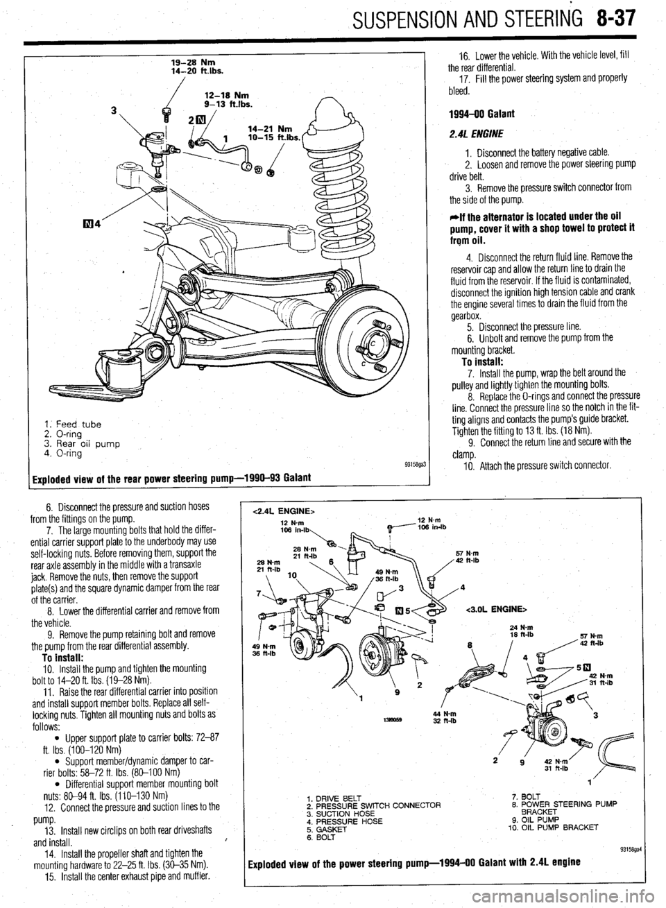
1. Feed tube
2. O-ring
3. Rear oil pump
4. O-ring
93158ga:
Exploded view of the rear power steering pump-1990-93 Galant
6. Disconnect the pressure and suction hoses
from the fittings on the pump.
7. The large mounting bolts that hold the differ-
ential carrier support plate to the underbody may use
self-locking nuts. Before removing them, support the
rear axle assembly in the middle with a transaxle
jack. Remove the nuts, then remove the support
plate(s) and the square dynamic damper from the rear
of the carrier.
8. Lower the differential carrier
and remove from
the vehicle.
9. Remove the pump retaining bolt and remove
the pump from the rear differential assembly.
To install: IO. Install the pump and tighten the mounting
bolt to 14-20 ft. Ibs. (19-28 Nm).
11. Raise the rear differential carrier into position
and install support member bolts. Replace all self-
locking nuts. Tighten all mounting nuts and bolts as
follows:
l Upper support plate to carrier bolts: 72-87
ft. Ibs. (100-120 Nm)
l Support member/dynamic damper to car-
rier bolts: 58-72 ft. Ibs. (80-100 Nm)
l Differential support member mounting bolt
nuts: 80-94 ft. Ibs. (110-130 Nm)
12. Connect the pressure and suction lines to the
pump.
13. Install new circlips on both rear driveshafts
and install. I
14.
Install the propeller shaft and tighten the
mounting hardware to 22-25 ft. Ibs. (30-35 Nm).
15. Install the center exhaust pipe and muffler.
1
16. Lower the vehicle. With the vehicle level, fill
the rear differential.
17. Fill the power steering system and properly
bleed.
1994-00 Galant
2.4L ENGINE
1. Disconnect the battery negative cable.
2. Loosen and remove the power steering pump
drive belt.
3. Remove the pressure switch connector from
the side of the pump.
*If the alternator is located under the oil
pump, cover it with a shop towel to protect it
frqm oil.
4. Disconnect the return fluid line. Remove the
reservoir cap and allow the return line to drain the
fluid from the reservoir. If the fluid is contaminated,
disconnect the ignition high tension cable and crank
the engine several times to drain the fluid from the
gearbox.
5. Disconnect the pressure line.
6. Unbolt and remove the pump from the
mounting bracket.
To install: 7. Install the pump, wrap the belt around the
pulley and lightly tighten the mounting bolts.
8. Replace the O-rings and connect the pressure
line. Connect the pressure line so the notch in the fit-
ting aligns and contacts the pump’s guide bracket.
Tighten the fitting to 13 ft. Ibs. (18 Nm).
9. Connect the return line and secure with the
clamp.
IO. Attach the pressure switch connector.
<2.4L ENGINE> 12 N-m 12 N-m
<3.OL ENGINE>
32 ft-lb
1. DRIVE BELT
2. PRESSURE SWITCH CONNECTOR
3. SUCTION HOSE
; i’;;‘;;RE HOSE 7. BOLT
8. ~O~~~E;TEER’NG PUMP
9. OIL PUMP
10. OIL PUMP BRACKET
6. BOLT
93158gal
Exploded view of the power steering pump-1994-00 Galant with 2.4L engine
Page 334 of 408
- 8-38 SUSPENSION AND STEERING
11. Adjust the power steering belt for proper ten-
sion and tighten the adjusting bolts.
12. Reconnect the negative battery cable.
13. Refill the reservoir and bleed the system.
3. Of EIJGINE
1. Disconnect the battery negative cable. 2. Disconnect the return fluid line. Remove the
reservoir cap and allow the return line to drain the
fluid from the reservoir. If the fluid is contaminated,
disconnect the ignition high tension cable and crank
the engine several times to drain the fluid from the
gear box.
3. Remove the power steering pump drive belt.
4. Remove the pressure switch connector from
the side of the pump.
5. If the alternator is located under the oil pump,
cover it with a shop towel to protect it from oil.
6. Disconnect the high pressure hose and the
return hose from the pump.
7. Remove the pump drive belt and unbolt the
pump from its bracket and remove the pump.
To install: 8. Install the pump, *rap the belt around the
pulley and tighten the bolts that secure the pump to
17 ft. Ibs. (24 Nm).
9. Replace the O-rings and connect the high
pressure hose. Connect the pressure line so the
notch in the fitting aligns and contacts the pump’s
guide bracket. Tighten the mounting nut with lock-
washer to 17 ft. Ibs. (24 Nm).
IO. Using a new hose clamp, connect the return
line.
11. Attach the pressure switch connector.
12. Adjust the belt tension and tighten the
adjust- ing bolts.
13. Refill the reservoir and bleed the system.
Diamante *
FRONT
. 1. Disconnect the battery negative cable. 2. Disconnect the return fluid line. Remove the
reservoir cap and allow the return line to drain the
fluid from the reservoir. If the fluid is contaminated,
disconnect the ignition high tension cable and crank
the engine several times to drain the fluid from the
gearbox.
3. Remove the power steering pump drive belt.
4. Remove the pressure switch connector from
the side of the pump.
5. If the alternator is located under the oil pump,
cover it with a shop towel to protect it from oil.
6. Disconnect the high pressure hose and the
return hose from the pump.
7. Remove the pump drive belt and unbolt the
pump from its bracket and remove the pump.
To install: 8. Install the pump, wrap the belt around the
pulley and tighten the bolts that secure the pump to
17 ft. Ibs. (24 Nm).
9. Replace the O-rings and connect the high
pressure hose. Connect the pressure line so the
notch in the fitting aligns and contacts the pump’s
guide bracket. Tighten the mounting nut with lock-
washer to 17 ft. Ibs. (24 Nm).
10. Using a new hose clamp, connect the return
line.
Il. Attach the pressure switch connector.
12. Adjust the belt tension and tighten the adjust-
ing bolts.
13. Refill the reservoir and bleed the system.
REAR
1. Disconnect the negative battery cable.
2. Drain the power steering fluid.
3. Remove the rear power steering pump heat
protector, located on the engine side of the differen-
tial on the transaxle.
4. Disconnect the pressure line from the pump.
5. Disconnect the suction hose from the pump.
6. Remove the mounting bolts and remove the
pump from the transaxle.
44
33
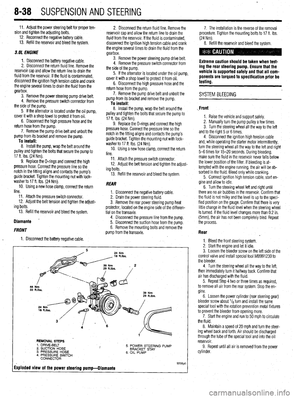
REMOVAL STEPS
5. POWER STEERING PUMP
BRACKET STAY
6. OIL PUMP 1. DRIVE-BELT
2. SUCTION HOSE I ’ 3. PRESSURE HOSE
4. PRESSURE SWITCH
CONNECTOR
Exploded view of the power steering pump-Diamante
. 93158ga5
7. The installation is the reverse of the removal
procedure. Tighten the mounting bolts to 17 ft. Ibs.
(24 Nm).
8. Refill the reservoir and bleed the system.
Extreme caution should be taken when test-
ing the rear steering pump. Ensure that the
vehicle is supported safely and that all com-
ponents are torqued to specification prior be
testing.
. SYSTEM BLEEDING
,Front
1. Raise the vehicle and support safely.
2. Manually turn the pump pulley a few times.
3. Turn the steering wheel all the way to the left
and to the right 5 or 6 times.
4. Disconnect the ignition high tension cable
and, while operating the starter motor intermittently,
turn the steering wheel all the way to the letI and right
5-6 times for 15-20 seconds. During bleeding,
make sure the fluid in the reservoir never falls below
the lower position of the filter. If bleeding is at-
tempted with the engine running, the air will be ab-
sorbed in the fluid. Bleed only while cranking.
5. Connect ignition high tension cable, start en-
gine and allow to idle.
6. Turn the steering wheel left and right until
there are no air bubbles in the reservoir. Confirm that
the fluid is not milky and the level is up to the speci-
fied position on the gauge. Confirm that there is very
little change in the fluid level when the steering wheel
is turned. If the fluid level changes more than 0.2 in.
(5mm), the air has not been completely bled. Repeat
the process.
Rear
.
1. Bleed the front steering system.
2. Start the engine and let it idle.
3. Loosen the bleeder screw on the left side of the
control valve and install special tool MB991230 to
the bleeder.
4. Turn the steering wheel all the way to the left,
then immediately turn it halfway back. Confirm that
air has discharged with the fluid.
5. Repeat Step 4 two or three times as required,
to remove all air from the rear system. Stop the en-
gine.
6. Loosen the power cylinder (rear steering gear)
bleeder screw about I/* turn and install the same
special tool with the rotation prevention metal fixtures
to prevent the bleeder from opening more.
7. Start the engine and run to 50 mph to circulate
the fluid.
8. Maintain a speed of 20 mph and turn the steer-
ing wheel back and forth. Air should be discharged ,
through the tube of the special tool and into the oil
reservoir.
9. Repeat until all air is removed from the power
cylinder.
Page 378 of 408

.
IO-10 BODYANDTRIM
4992 models>
10. Remove the retaining screws and the floor
console from the vehicle.
To
install: 11. Install the floor console in position in the ve-
hicle and secure with the retaining screws.
12. The remainder of installation is the reverse of
removal.
1. Ashtray or floor co
2. Switch or plug
REMOVAL&INSTALLATION
u See Figures 40 thru 49
1. Disconnect the negative battery cable.
2. If equipped with manual windows, insert a
ind the window regulator handle and
9315@38 Fig. 38 Floor console assemblv-1992-96 shop towel beh
Fig. 40 Remove the inside door rele
9315Gq39 Fia. 39 Floor console assemblv-1997-00 die cup retaining screw . . .
Diumante , I ,
r+Dn some models, the seat belts are routed
through the console. Carefully slide the belts
out of the hole.
7. The installation is the reverse of removal.
Front
1. Disconnect the negative battery cable. If
equipped with SRS, wrap the cable in insulated tape,
then wait at least 60 seconds before continuing to al-
low the SRS system time to disable.
9315opO3 Fig. 42 Remove the inside pull handle re-
If equipped with SRS, be careful not to let
the console bump against the SRS-ECU dur-
ing removal and installation. taining screw cover , . .
2. If equipped, remove the rear floor console.
3. If necessary, remove the ashtray and cup
holder assemblies.
4. If equipped, remove the carpet inserts from
the floor console assembly.
5. On manual transaxle equipped models, re-
move the manual transaxle shifter knob.
6. On automatic transaxle equipped models, re-
move the transaxle shift lever trim plate.
7. Remove the screw plugs in the side covers.
Remove the retainer screws and the side covers from
the vehicle.
8. Remove the front mounting screw cover from
the floor console.
9. Label and detach the electrical wire harness
connections for the floor console. Fig. 44 Release the front retaining clips,
and lift the handle and switch assembly
from the door oanel push the retainer clip outward. Once the clip is re-
moved, remove the window glass requlator handle
and escutcheon.
3. If equipped with power windows/locks, re-
move the escutcheon panel (control panel) and de-
tach the electrical connectors.
4. If equipped, remove the door grip/pull handle
mounting screws and the grip from the door panel.
5. Remove the door pull handle cover. Remove
the pull handle, if equipped.
6. Remove the door trim panel retaining screws.
7. Pull the door panel gently from the door. The
panel is retained by spring clips. To separate the
clips from the door, slide a small prytool behind the
clip and carefully pull the clip, with the door panel,
outward. Try not to bend the door panel or damaqe
may occur..
Fig. 41 . . . then remove the inside door re-
lease handle cup
Fig. 43
V . . then remove the inside pull han-
dle retaining screw
Fig. 45 Detach the electrical connectors
from the door lock and window switches
isembly ,,,’ ” then remove the switch plate/handle as-
Page 379 of 408
BODYANDTRiVl 1041
8. llnm all mtainar din!: xc! .wnnratmi rmnnve -.*I-_.. .I._. ..I. -..r-~.--“* -.-.- I( .” .I._._ the dot jr panel assembly.
9. Carefully remove any retainer clips that re-
mained in the door during panel removal. If dam-
aaed. reolace the retainer clios.
- 10. if necessary, remove’the waterproof film from
the door.
To install:
11. If removed, install the waterproof film from
. .
tne aoor.
12. Install and missing or damaged retainer clips
into the door panel.
- .- ” - 13. . - Install the door panel onto the vehicle. Push . - -. ” - ret;liners intn the hnlss in the rlnnr until thev lnck intn . - - - -. -. . . . “, - ” . .- position. If any clips do not lock, replace with new 4. Remove the lock cylinder from the trunk lid,
hatch, or tailgate. T- 1-a-11.
REMOVAL &INSTALLATION
1. Disconnect the r
negative battery cable.
2. If necessary, ren love any trim in on the under-
side of the trunk lid, hz
Itch, or tailgate.
3. Release locking tab retaining the lock cylinder
to outside handle.
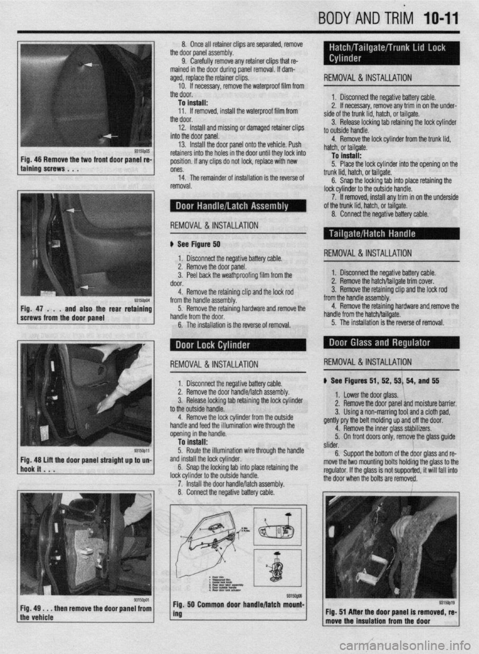
9315opo5 1 Fig. 46 Remove the two front door panel re-
taining screws . , . IU Inrlall; 5. Place the lock cylinder into the opening on the
ones.
14. The remainder of installation is the reverse of
removal. trunk lid, hatch, or tailsate. -
6. Snap the locking tab into place retaining the
lock cylinder to the outside handle.
7. If removed, install any trim in on the underside
of the trunk lid, hatch, or tailgate.
8. Connect the negative battery able:
REMOVAL &INSTALLATION
II See Figurd 50
1‘ &connect the negative battery cable. REMOVAL&INSTALLATION
9315ctpm Fig. 47 . . .
and also the rear retaining
screws from the door panel 2. Remove the door panel.
3. Peel back the weathproofing film from the
door.
4. Remove the retaining clip and the lock rod
from the handle assembly.
5. Remove the retaining hardware and remove the
handle from the door.
6. The installation is the reverse of removal. 1. Disconnect the negative battery cable.
2. Remove the hatch/tailgate trim cover.
3. Remove the retaining clip and the lock rod
from the handle assembly.
4. Remove the retaining hardware and.remove the
handle from the hatch/tailgate.
5. The installation is the reverse of removal.
I 1. Disconnect the neaative batterv cable. ) See Figures 51, 52, 53/ 54, and 55 REMOVAL&INSTALLATION REMOVAL&INSTALLATION
2. Remove the door ~andle/latchassembly.
3. Release locking tab retaining the lock cylinder
to the outside handle.
4. Remove the lock cylinder from the outside
handle and feed the illumination wire through the
opening in the handle.
To install:
5. Route the illumination wire through the handle
and install the lock cylinder.
6. Snap the locking tab into place retaining the
lock cvlinder to the outside handle.
7. ‘Install the door handle/latch assembly.
8. Connect the negative battery cable. 1. Lower the door glass. ‘1,
2. Remove the door panel and moisture barrier.
3. Using a non-marring tool and a cloth pad,
gently pry the belt molding up and off the door.
4. Remove the inner glass sthbilizers.
5. On front doors only, remove the glass guide
/
slider.
6. Support the bottom of the door glass and re-
move the two mounting bolts holdirtg the glass to the
regulator. If the glass is not supporfed, it will fail into
+I%? Ann. . ..hmn hr. l..4+s are remove&.
9315opa Fig, 49 . . . then remove the door panel from
the vehicle 50 Common door handle/latch mount-
I
, Flg. 51 After the door panel is removed, re-
move the Insulation from the door
Page 390 of 408
11-8 TROUBLESHOOTING
Ignition systems may be controlled by, or linked to, the engine fuel management sys-
tem. Similar to the fuel injection system, these ignition systems rely on electronic sen-
sors for information to determine the optimum ignition timing for a given engine speed
and load. Some ignition systems no longer allow the ignition timing to be adjusted.
Feedback from low voltage electrical sensors provide information to the control unit to
determine the amount of ignition advance. On these systems, if a failure occurs the failed
component must be replaced. Before replacing suspected failed electrical components,
carefully inspect the wiring and electrical connectors to the related components. Make
sure the electrical connectors are fully connected, clean and not physically damaged. If
necessary, clean the electrical contacts using electrical contact cleaner. The use of clean-
ing agents not specifically designed for electrical contacts should be avoided, as they
could leave a surface film or damage the insulation of the wiring.
1. Engine makes a knocking or pinging noise when accelerating
a. Check the octane rating of the fuel being used. Depending on the type of driving or
driving conditions, it may be necessary to use a higher octane fuel.
b. Verify the ignition system settings and operation. Improperly adjusted ignition timing
or a failed component, such as a knock sensor, may cause the ignition timing to ad-
vance excessively or prematurely. Check the ignition system operation and adjust, or
replace components as needed.
c. Check the spark plug gap, heat range and condition. If the vehicle is operated in se-
vere operating conditions or at continuous high speeds, use a colder heat range spark
plug. Adjust the spark plug gap to the manufacturer’s recommended specification and
replace worn or damaged spark plugs.
2. Sfarter motor grinds when used
a. Examine the starter pinion gear and the engine ring gear for damage, and replace dam-
aged parts.
b. Check the starter mounting bolts and housing. If the housing is cracked or damaged
replace the starter motor and check the mounting bolts for tightness.
3. Engine makes a screeching noise
a. Check the accessory drive belts for looseness and adjust as necessary.
b. Check the accessory drive belt tensioners for seizing or excessive bearing noises and
replace if loose, binding, or excessively noisy.
c. Check for a seizing water pump. The pump may not be leaking; however, the bearing
may be faulty or the impeller loose and jammed. Replace the water pump.
4. Engine makes a growling noise
a. Check for a loose or failing water pump. Replace the pump and engine coolant.
b. Check the accessory drive belt tensioners for excessive bearing noises and replace if
loose or excessively noisy.
5. Engine makes a ticking or tapping noise
a. On vehicles with hydraulic lash adjusters, check for low or dirty engine oil and top off
or replace the engine oil and filter.
b. On vehicles with hydraulic lash adjusters, check for collapsed lifters and replace failed
components.
c. On vehicles with hydraulic lash adjusters, check for low oil pressure caused by a re-
stricted oil filter, worn engine oil pump, or oil pressure relief valve.
d. On vehicles with manually adjusted valves, check for excessive valve clearance or
worn valve train parts. Adjust the valves to specification or replace worn and defective
parts.
e. Check for a loose or improperly tensioned timing belt or timing chain and adjust or re-
place parts as necessary.
f. Check for a bent or sticking exhaust or intake valve. Remove the engine cylinder head
to access and replace.
6. Engine makes a heavy knocking noise
a. Check for a loose crankshaft pulley or flywheel; replace and torque the mounting
bolt(s) to specification.
b. Check for a bent connecting rod caused by a hydro-lock condition. Engine disassem-
bly is necessary to inspect for damaged and needed replacement parts.
c. Check for excessive engine rod bearing wear or damage. This condition is also asso-
ciated with low engine oil pressure and will require engine disassembly to inspect for
damaged and needed replacement parts,
7. Vehicle has a fuel odor when driven ’ a. Check the fuel gauge level. If the fuel gauge registers full, it is possible that the odor is
caused by being filled beyond capacity, or some spillage occurred during refueling.
The odor should clear after driving an hour, or twenty miles, allowing the vapor canis-
ter to purge.
b. Check the fuel filler cap for looseness or seepage. Check the cap tightness and, if
loose, properly secure. If seepage is noted, replace the filler cap.
c. Check for loose hose clamps, cracked or damaged fuel delivery and return lines, or
leaking components or seals, and replace or repair as necessary. d. Check the vehicle’s fuel economy. If fuel consumption has increased due to a failed
component, or if the fuel is not properly ignited due to an ignition related failure, the
catalytic converter may become contaminated. This condition may also trigger the
check engine warning light. Check the spark plugs for a dark, rich condition or verify
the condition by testing the vehicle’s emissions. Replace fuel fouled spark plugs, and
test and replace failed components as necessary.
5. Vehicle has a rotten egg odor when driven
a. Check for a leaking intake gasket or vacuum leak causing a lean running condition. A
lean mixture may result in increased exhaust temperatures, causing the catalytic con-
verter to run hotter than normal. This condition may also trigger the check engine
warning light. Check and repair the vacuum leaks as necessary.
b. Check the vehicle’s alternator and battery condition. If the alternator is overcharging,
the battery electrolyte can be boiled from the battery, and the battery casing may begin
to crack, swell or bulge, damaging or shorting the battery internally. If this has oc-
curred, neutralize the battery mounting area with a suitable baking soda and water
mixture or equivalent, and replace the alternator or voltage regulator. Inspect, service,
and load test the battery, and replace if necessary.
9. Vehicle has a sweet odor when driven
a. Check for an engine coolant leak caused by a seeping radiator cap, loose hose clamp,
weeping cooling system seal, gasket or cooling system hose and replace or repair as
needed.
b. Check for a coolant leak from the radiator, coolant reservoir, heater control valve or
under the dashboard from the heater core, and replace the failed part as necessary.
c. Check the engine’s exhaust for white smoke in addition to a sweet odor. The presence
of white, steamy smoke with a sweet odor indicates coolant leaking into the combus-
tion chamber. Possible causes include a failed head gasket, cracked engine block or
cylinder head. Other symptoms of this condition include a white paste build-up on the
inside of the oil filler cap, and softened, deformed or bulging radiator hoses.
19. Engine vibraies when idling
a. Check for loose, collapsed, or damaged engine or transmission mounts and repair or
replace as necessary.
b. Check for loose or damaged engine covers or shields and secure or replace as neces-
sary.
11. Engine vibrates during acceleration
a. Check for missing, loose or damaged exhaust system hangers and mounts; replace or
repair as necessary.
b. Check the exhaust system routing and fit for adequate clearance or potential rubbing;
repair or adjust as necessary.
7. Battery goes dead while driving
a. Check the battery condition. Replace the battery if the battery will not hold a charge or
fails a battery load test. If the battery loses fluid while driving, check for an overcharg-
ing condition. If the alternator is overcharging, replace the alternator or voltage regula-
tor. (A voltage regulator is typically built into the alternator, necessitating alternator re-
placement or overhaul.)
b. Check the battery cable condition. Clean or replace corroded cables and clean the bat-
tery terminals.
c. Check the alternator and voltage regulator operation. If the charging system is over or
undercharging, replace the alternator or voltage regulator, or both.
d. Inspect the wiring and wire connectors at the alternator for looseness, a missing .
ground or defective terminal, and repair as necessary.
e. Inspect the alternator drive belt tension, tensioners and condition. Properly tension the
drive belt, replace weak or broken tensioners, and replace the drive belt if worn or
cracked.
2. Battery goes dead overnight
a. Check the battery condition. Replace the battery if the battery will not hold a charge or
fails a battery load test.
b. Check for a voltage draw, such as a trunk light, interior light or glove box light staying
on. Check light switch position and operation, and replace if defective.
c. Check the alternator for an internally failed diode, and replace the alternator if defec-
tive.
1. Engine overheats
a. Check the coolant level. Set the heater temperature to full hot and check for internal air
pockets, bleed the cooling system and inspect for leakage. Top off the cooling system
with the correct coolant mixture.
b. Pressure test the cooling system and radiator cap for leaks. Check for seepage caused
by loose hose clamps, failed coolant hoses, and cooling system components such as
the heater control valve, heater core, radiator, radiator cap, and water pump. Replace
defective parts and fill the cooling system with the recommended coolant mixture.
Page 391 of 408
TROUBLESHOOTING 11-9
c. On vehicles with electrically controlled cooling fans, check the cooling fan operation.
Check for blown fuses or defective fan motors, temperature sensors and relays, and
replace failed components.
d. Check for a coolant leak caused by a failed head gasket, or a porous water jacket cast-
ing in the cylinder head or engine block. Replace defective parts as necessary.
e. Check for an internally restricted radiator. Flush the radiator or replace if the blockage
is too severe for flushing.
f. Check for a damaged water pump. If coolant circulation is poor, check for a loose wa-
ter pump impeller. If the impeller is loose, replace the water pump.
2. Engine loses coolant
a. Pressure test the cooling system and radiator cap for leaks. Check for seepage caused
by loose hose clamps, failed coolant hoses, and cooling system components such as
the heater control valve, heater core, radiator, radiator cap, and water pump. Replace
defective parts and fill the cooling system with the recommended coolant mixture.
b. Check for a coolant leak caused by a failed head gasket, or a porous water jacket cast-
ing in the cylinder head or engine block. Replace defective parts as necessary.
3. Engine temperature remains co/d when driving
a. Check the thermostat operation. Replace the thermostat if it sticks in the open posi-
tion.
b. On vehicles with electrically controlled cooling fans, check the cooling fan operation.
Check for defective temperature sensors and stuck relays, and replace failed compo-
nents.
c. Check temperature gauge operation if equipped to verify proper operation of the
gauge. Check the sensors and wiring for defects, and repair or replace defective com-
ponents.
4. Engine runs hot
a. Check for an internally restricted radiator. Flush the radiator or replace if the blockage
is too severe for flushing.
b. Check for a loose or slipping water pump drive belt. Inspect the drive belt condition.
Replace the belt if brittle, cracked or damaged. Check the pulley condition and prop-
erly tension the belt.
c. Check the cooling fan operation. Replace defective fan motors, sensors or relays as
necessary.
d. Check temperature gauge operation if equipped to verify proper operation of the
gauge. Check the sensors and wiring for defects, and repair or replace defective com-
ponents.
e. Check the coolant level. Set the heater temperature to full hot, check for internal air
pockets, bleed the cooling system and inspect for leakage. Top off the cooling system
with the correct coolant mixture. Once the engine is cool, recheck the fluid level and
top off as needed.
NOTE: The engine cooling system can also be affected by an engine’s me-
chanical condition. A failed head gasket or a porous casting in the engine
block or cylinder head could cause a loss of coolant and result in engine
overheating.
Some cooling systems rely on electrically driven cooling fans to cool the radiator and
use electrical temperature sensors and relays to operate the cooling fan. When diagnos-
ing these systems, check for blown fuses, damaged wires and verify that the electrical
connections are fully connected, clean and not physically damaged. If necessary, clean
the electrical contacts using electrical contact cleaner. The use of cleaning igents not specifically designed for electrical contacts could leave a film or damage the insulation of
the wiring.
1. Exhaust rattles at idle speed
a. Check the engine and transmission mounts and replace mounts showing signs of
damage or wear.
b. Check the exhaust hangers, brackets and mounts. Replace broken, missing or dam-
aged mounts.
c. Check for internal damage to mufflers and catalytic converters. The broken pieces from
the defective component may travel in the direction of the exhaust flow and collect
and/or create a blockage in a component other than the one which failed, causing en-
gine running and stalling problems. Another symptom of a restricted exhaust is low
engine manifold vacuum. Remove the exhaust system and carefully remove any loose
or broken pieces, then replace any failed or damaged parts as necessary.
d. Check the exhaust system clearance, routing and alignment. If the exhaust is making
contact with the vehicle in any manner, loosen and reposition the exhaust system.
2. Exhaust system vibrates when driving
a. Check the exhaust hangers, brackets and mounts. Replace broken, missing or dam-
aged mounts.
b. Check the exhaust system clearance, routing and alignment. If the exhaust is making
contact with the vehicle in any manner, check for bent or damaged components and
replace, then loosen and reposition the exhaust system.
c. Check for internal damage to mufflers and catalytic converters. The broken pieces from
the defective component may travel in the direction of the exhaust flow and collect
and/or create a blockage in a component other than the one which failed, causing en-
gine running and stalling problems. Another symptom of a restricted exhaust is low
engine manifold vacuum. Remove the exhaust system and carefully remove any loose
or broken pieces, then replace any failed or damaged parts as necessary.
3. Exhaust system hangs too low
a. Check the exhaust hangers, brackets and mounts. Replace broken, missing or dam-
aged mounts.
b. Check the exhaust routing and alignment. Check and replace bent or damaged com-
ponents. If the exhaust is not routed properly, loosen and reposition the exhaust sys-
tern.
4. Exhaust sounds loud
a. Check the system for looseness and leaks. Check the exhaust pipes, clamps, flange
bolts and manifold fasteners for tightness. Check and replace any failed gaskets.
b. Check and replace exhaust silencers that have a loss of efficiency due to internally
broken baffles or worn packing material.
c. Check for missing mufflers and silencers that have been replaced with straight pipes
or with non-original equipment silencers.
NOTE: Exhaust system rattles, vibration and proper alignment should not
be overlooked. Excessive vibration caused by collapsed engine mounts,
damaged or missing exhaust hangers and misalignment may cause surface
cracks and broken welds, creating exhaust leaks or internal damage to ex-
haust components such as the catalytic converter, creating a restriction to
exhaust flow and loss of power.
1. Transmission shit& erratically
a. Check and if not within the recommended range, add or remove transmission fluid to
obtain the correct fluid level. Always use the recommended fluid type when adding
transmission fluid.
b. Check the fluid level condition. If the fluid has become contaminated, fatigued from
excessive heat or exhibits a burning odor, change the transmission fluid and filter us-
ing the recommended type and amount of fluid. A fluid which exhibits a burning odor
indicates that the transmission has been slipping internally and may require future re-
pairs.
c. Check for an improperly installed transmission filter, or missing filter gasket, and re-
pair as necessary.
d. Check for loose or leaking gaskets, pressure lines and fittings, and repair or replace as
necessary.
e. Check for loose or disconnected shift and throttle linkages or vacuum hoses, and re-
pair as necessary. ,
2. Transmission will not engage
a. Check the shift linkage for looseness, wear and proper adjustment, and repair as nec-
essary. b. Check for a loss of transmission fluid and top off as needed with the recommended
fluid.
c. If the transmission does not engage with the shift linkage correctly installed and the
proper fluid level, internal damage has likely occurred, requiring transmission removal
and disassembly.
3. Transmission will not downshift during heavy acceleration
a. On computer controlled transmissions, check for failed sensors or control units and
repair or replace defective components.
b. On vehicles with kickdown linkages or vacuum servos, check for proper linkage ad-
justment or leaking vacuum hoses or servo units.
NOTE: Mlany automatic transmissions use an electronic control module,
electrical sensors and solenoids to control transmission shifting. When
troubleshooting a vehicle with this type of system, be sure the electrical
connectors are fully connected, clean and not physically damaged. If nec-
essary, clean the electrical contacts using electrical contact cleaner. The
use of cleaning agents not specifically designed for electrical contacts
could leave a film or damage the insulation of the wiring.
Page 399 of 408
GLOSSARY 11-17
AIR/FUEL RATIO: The ratio of air-to-gasoline by weight in the fuel mixture
drawn into the engine.
AIR INJECTION: One method of reducing harmful exhaust emissions by in-
jecting air into each of the exhaust ports of an engine. The fresh air entering
the hot exhaust manifold causes any remaining fuel to be burned before it can
exit the tailpipe.
ALTERNATOR: A device which produces AC (alternating current) which is
converted to DC (direct current) to charge the car battery.
AMMETER: An instrument, calibrated in amperes, used to measure the flow
of an electrical current in a circuit. Ammeters are always connected in series
with the circuit being tested.
AMPERE: The rate of flow of electrical current present when one volt of elec-
trical pressure is applied against one ohm of electrical resistance.
ANALOG COMPUTER: Any microprocessor that uses similar (analogous)
electrical signals to make its calculations.
ARMATURE: A laminated, soft iron core wrapped by a wire that converts elec-
trical energy to mechanical energy as in a motor or relay. When rotated in
a magnetic field, it changes mechanical energy into electrical energy as in a
generator.
ATMOSPHERIC PRESSURE: The pressure on the Earth’s surface caused
by the weight of the air in the atmosphere. At sea level, this pressure is 14.7
psi at 32°F (101 kPa at OOC).
ATOMIZATION: The breaking down of a liquid into a fine mist that can be
suspended in air.
AXIAL PLAY: Movement parallel to a shaft or bearing bore.
BACKFIRE: The sudden combustion of gases in the intake or exhaust sys-
tem that results in a loud explosion.
BACKLASH: The clearance or play between two parts, such as meshed gears.
BACKPRESSURE: Restrictions in the exhaust system that slow the exit of
exhaust gases from the combustion chamber.
BAKELITE[reg]: A heat resistant, plastic insulator material commonly used
in printed circuit boards and transistorized components.
BALL BEARING: A bearingmade up of hardened inner and outer races be-
tween which hardened steel’balls roll.
BALLAST RESISTOR: A resistor in the primary ignition circuit that lowers
voltage after the engine is started to reduce wear on ignition components.
BEARING: A friction reducing, supportive device usually located between a
stationary part and a moving part.
BI-METAL TEMPERATURE SENSOR: Anv sensor or switch made of two
dissimilar types of metal that bend when heated or cooled due to the different
expansion rates of the alloys. These types of sensors usually function as an
on/off switch. BLOW-BY: Combustion gases, composed of water vapor and unburned fuel,
that leak past the piston rings into the crankcase during normal engine oper-
ation. These gases are removed by the PCV system to prevent the buildup of
harmful acids in the crankcase.
BRAKE PAD: A brake shoe and lining assembly used with disc brakes.
BRAKE SHOE: The backing for the brake lining. The term is, however, usu-
ally applied to the assembly of the brake backing and lining.
BUSHING: A liner, usually removable, for a bearing; an anti-friction liner used
in place of a bearing.
CALIPER: A hydraulically activated device in a disc brake system, which is
mounted straddling the brake rotor (disc). The caliper contains at least one
piston and two brake pads. Hydraulic pressure on the piston(s) forces the pads
against the rotor.
CAMSHAFT: A shaft in the engine on which are the lobes (cams) which op-
erate the valves. The camshaft is driven by the crankshaft, via a belt, chain or
gears, at one half the crankshaft speed.
CAPACITOR: A device which stores an electrical charge.
CARBON MONOXIDE (CO): A colorless, odorless gas given off as a nor-
mal byproduct of combustion. It is poisonous and extremely dangerous in con-
fined areas, building up slowly to toxic levels without warning if adequate ven-
tilation is not available.
CARBURETOR: A device, usually mounted on the intake manifold of an en-
gine, which mixes the air and fuel in the proper proportion to allow even com-
bustion
CATALYTIC CONVERTER: A device installed in the exhaust system, like a
muffler, that converts harmful byproducts of combustion into carbon dioxide
and water vapor by means of a heat-producing chemical reaction.
CENTRIFUGAL ADVANCE: A mechanical method of advancing the spark
timing by using flyweights in the distributor that react to centrifugal force gen-
erated by the distributor shaft rotation.
CHECK VALVE: Any one-way valve installed to permit the flow of air, fuel or
vacuum in one direction only.
CHOKE: The valve/plate that restricts the amount of air entering an engine on
the induction stroke, thereby enriching the air:fuel ratio.
CIRCUIT: Any unbroken path through which an electrical current can flow.
Also used to describe fuel flow in some instances.
CIRCUIT BREAKER: A switch which protects an electrical circuit from
overload by opening the circuit when the current flow exceeds a pre-
determined level. Some circuit breakers must be reset manually, while most
reset automatically.
COIL (IGNITION): Part of the ignition system that boosts the relatively low
voltage supplied by the car’s electrical system to the high voltage required to
fire the spark plugs.
Page 403 of 408

ADJUSTMENTS 2-3
ADJUSTMENTS 2-5
ADJUSTMENTS 7-2
AIR BAG (SUPPLEMENTAL RESTRAINT SYSTEM) 6-7
AIR CONDITIONING COMPONENTS 6-11
REMOVAL & INSTALLATION 6-11
AIRCLEANER(ELEMENT) I-14
REMOVAL&INSTALLATION I-14
AIR CONDITIONING SYSTEM 1-28
ALLWHEELDRIVEMODELS l-44
ALTERNATOR 2-8
ALTERNATORPRECAUTIONS 2-8
ANTENNA IO-4
REPLACEMENT IO-4
ANTI-LOCK BRAKE SYSTEM 9-24
ANTI-LOCK CONTROL UNIT 9-27
REMOVAL & INSTALLATION 9-27
AUTOMATICTRANSAXLEASSEMBLY 7-10
ADJUSTMENTS 7-13
REMOVAL&INSTALLATION 7-10
AUTOMATIC TRANSAXLE 7-10
AUTOMATICTRANSAXLE l-36
DRAIN &REFILL l-36
FLUIDRECOMMENDATIONS l-36
LEVELCHECK l-36
PAN&FILTER SERVICE l-36
AVOIDINGTHEMOSTCOMMON MISTAKES l-2
AVOIDINGTROUBLE l-2
AXLE HOUSING ASSEMBLY 7-16
REMOVAL&INSTALLATION 7-16
BACK-UP LIGHT SWITCH 7-2
REMOVAL & INSTALLATION 7-2
BALANCE SHAFT 3-54
REMOVAL & INSTALLATION 3-54
BASIC ELECTRICAL THEORY 6-2
HOW DOES ELECTRlClTYWORK:THEWATERANALOGY 6-2
OHM'S LAW 6-2
BASIC FUEL SYSTEM DIAGNOSIS 5-2
BASIC OPERATING PRINCIPLES 9-2
DISC BRAKES 9-2
DRUMBRAKES 9-2 .
POWER BOOSTERS 9-2
BATTERY CABLES 6-7
BATTERY I-16
BATTERYFLUID I-16
CABLES I-17
CHARGING I-18
GENERALMAINTENANCE I-16
PRECAUTIONS 1-16
REPLACEMENT I-18
BELTS I-18
ADJUSTMENT I-18
INSPECTION I-18
REMOVAL &INSTALLATION 1-18
BLEEDING BRAKESYSTEM 9-7
BLEEDING THEABS SYSTEM 9-30
BLOWERMOTOR 6-7
REMOVAL &INSTALLATION 6-7
BODYLUBRICATIONANDMAINTENANCE l-43
BOLTS,NUTSANDOTHERTHREADED RETAINERS l-6
BRAKE CALIPER 9-11
OVERHAUL 9-12
REMOVAL & INSTALLATION 9-11
BRAKE DISC (ROTOR) 9-13
1
INSPECTION 9-14
REMOVAL &INSTALLATION 9-13
BRAKEDRUMS 9-16
INSPECTION 9-16
REMOVAL&INSTALLATION. 9-16
BRAKE HOSESAND LINES 9-6
REMOVAL&INSTALLATION 9-6
BRAKE LIGHT SWITCH 9-3
Page 407 of 408
MASTER INDEX 11-25 -
REAROUTPUTSHAFTSEAL 7-14
TESTING 6-5
REMOVAL & INSTALLATION 7-14
' THERMOSTAT 3-7
REAR SUSPENSION 8-18 REMOVAL & INSTALLATION 3-7
REAR WINDOW WIPER SWITCH 6-19 THROTTLE BODY 5-3
REMOVAL&INSTALLATION 6-19 REMOVAL & INSTALLATION 5-3
REARDRlVEAXLE(AWDGALANTONLY) l-38
THROTTLEPOSITIONSENSOR 4-13
DRAIN &REFILL 1-38
OPERATION 4-13
FLUIDRECOMMENDATIONS 1-38 , REMOVAL&INSTALLATION 4-13
LEVELCHECK l-38
TESTING 4-13
REGULATOR 2-10 TIMING COVERAND BELT 3-36
REMOVAL&INSTALLATION 2-10
INSPECTION 3-48
RELIEVING FUELSYSTEM PRESSURE 5-3 REMOVAL & INSTALLATION 3-36
ROCKERARM(VALVE)COVER 3-1
TIMING BELTS l-20
REMOVAL & INSTALLATION 3-1
INSPECTION I-20
ROCKER ARM/SHAFTS 3-4
TIRESANDWHEELS I-30
REMOVAL & INSTALLATION 3-4
CAREOFSPECIALWHEELS l-32
ROUTINE MAINTENANCE AND TUNE-UP 1-14 INFLATION & INSPECTION I-31
SEATS IO-IO
TIRE DESIGN I-31
REMOVAL&INSTALLATION IO-IO TIRE ROTATION I-30
SENDING UNITS 2-11
TIRESTORAGE I-31
SERIAL NUMBER IDENTIFICATION l-10
TONE (EXCITER) RING 9-29
SERVICING YOUR VEHICLE SAFELY I-4
REMOVAL & INSTALLATION 9-29
SHOCKABSORBERAND COILSPRING 8-8
TOOLS AND EQUIPMENT 1-2
OVERHAUL 8-9
TORQUE 1-7
REMOVAL&INSTALLATION 8-8 TORQUEANGLEMETERS l-9
SIGNAL AND MARKER LIGHTS 6-21
TORQUEWRENCHES l-7
REMOVAL & INSTALLATION 6-21
TOWING THE VEHICLE 1-44
SPARKPLUG WIRES 1-24
TRAINING ARM 8-24
REMOVAL&INSTALLATION 1-24
REMOVAL & INSTALLATION 8-24
TESTING 1-24
TRANSAXLEIDENTIFICATION I-10
SPARKPLUGS l-22
TRANSFER CASE ASSEMBLY 7-14
INSPECTION &GAPPING l-23
REMOVAL & INSTALLATION 7-14
REMOVAL&INSTALLATION 1-22
TRANSFER CASE 7-14
SPARKPLUGHEATRANGE 1-22
TRANSFERCASE(AWD GALANT ONLY) 1-38
SPEAKERS 6-14
DRAIN &REFILL 1-38
REMOVAL & INSTALLATION 6-14
FLUIDRECOMMENDATIONS 1-38
SPECIALTOOLS 1-4
LEVELCHECK 1-38
SPEED SENSORS 9-28
TRANSFERCASE(AWDGALANTONLY) I-10
REMOVAL & INSTALLATION 9-28
TROUBLESHOOTING ELECTRICALSYSTEMS 6-5
STANDARDANDMETRIC MEASUREMENTS l-9
OPEN CIRCUITS 6-5
STARTER 2-10
RESISTANCE 6-8
REMOVAL&INSTALLATION 2-11
SHORT CIRCUITS 6-6
TESTING 2-10
VOLTAGEDROP 6-6
STARTING SYSTEM 2-10
VOLTAGE 6-6
STEERING LINKAGE 8-30
TRUNK LID IO-3
REMOVAL &INSTALLATION 8-30
ALIGNMENT IO-3
STEERING WHEEL 8-27
REMOVAL & INSTALLATION IO-3
REMOVAL &INSTALLATION 8-27
TURBOCHARGER 3-17
STEERING 8-27
REMOVAL & INSTALLATION 3-17
STRUT AND COIL SPRING
8-21
UNDERSTANDING AND TROUBLESHOOTING ELECTRICAL
OVERHAUL 8-22
SYSTEMS 6-2
REMOVAL & INSTALLATION 8-21
UNDERSTANDINGTHEAUTOMATICTRANSAXLE 7-10
STUBAXLESHAFT,BEARlNG AND SEAL 7-15
REMOVAL & INSTALLATION 7-10
REMOVAL&INSTALLATION 7-15
UNDERSTANDINGTHECLUTCH 7-7
SWAY BAR 8-12
ADJUSTMENTS 7-8
REMOVAL 8, INSTALLATION 8-12
REMOVAL&INSTALLATION 7-7
SWAY BAR 8-25
UNDERSTANDINGTHE MANUALTRANSAXLE 7-2
REMOVAL&INSTALLATION 8-25
SHIFT LINKAGE 7-2
TAILGATE/HATCH HANDLE lo-19
UPPER BALLJOINT 8-9
REMOVAL &INSTALLATION lo-10
INSPECTION 8-9
TAILGATE IO-3
REMOVAL &INSTALLATION 8-9
ALIGNMENT IO-3 i'
UPPER CONTROLARM 8-10
REMOVAL & INSTALLATION IO-3
REMOVAL & INSTALLATION 8-10
TANKASSEMBLY 5-10
UPPER CONTROL ARMS 8-22
REMOVAL&INSTALLATION 5-10
REMOVAL & INSTALLATION 8-22
TEST EQUIPMENT 6-4
VACUUM DIAGRAMS 4-36
JUMPER WIRES 6-4
VALVE LASH 1-27
MULTIMETERS 6-5
ADJUSTMENT 1-27
TEST LIGHTS 6-4
VEHICLE IDENTIFICATION NUMBER I-10