jump start MITSUBISHI DIAMANTE 1900 Repair Manual
[x] Cancel search | Manufacturer: MITSUBISHI, Model Year: 1900, Model line: DIAMANTE, Model: MITSUBISHI DIAMANTE 1900Pages: 408, PDF Size: 71.03 MB
Page 17 of 408
l
1-18 GENERALINFORMATIONAND MAINTENANCE
the clamps and remove the cables, negative cable
first. On batteries with posts on top, the use of a
puller specially made for this purpose is recom-
mended. These are inexoensive and available in most alternator or turn the adjusting bolt to adjust belt ten-
sion. Once the desired value is reached, secure the
bolt or locknut and recheck tension.
d”t” lJdlL> X”lt;>. 31°C LtXlllllldl lJdllt2)’ MLJIC, dlt’ X- cured with a small bolt. ST& I REMOVAL &INSTALLATION
Clean the cable clamps and the battery terminal I
with a wire brush, until all corrosion, grease, etc., is
removed and the metal is shinv. It is esneciallv imnnr-
tant to c
knife is useful nere), since a smart
material or oxidation there will pre Clean the cable clamps and the battery terminal
with a wire brush, until all corrosion, grease, etc., is
removed and the metal is shiny. It is especially impor-
tant to clean the inside of the clamp thoroughly (an old
knife is useful here), since a small deposit of foreign
material or oxidation there will prevent a sound electri-
cal connection and inhibit either starting or charging.
Special tools are available for cleaning these parts,
one type for conventional top post batteries and an-
other type for side terminal batteries. It is also a good
idea to apply some dielectric grease to the terminal, as
this will aid in the prevention of corrosion,
After the clamps and terminals are clean, reinstall
the cables, negative cable last; DO NOT hammer the
clamps onto battery posts. Tighten the clamps se-
curely, but do not distort them. Give the clamps and
terminals a thin external coating of grease after in-
stallation, to retard corrosion.
Check the cables at the same time that the terminals
are cleaned. If the cable insulation is cracked or bro-
ken, or if the ends are frayed, the cable should be re-
placed with a new cable of the same length and gauge.
CHARGING
the cables, negative cable last; DO NOT hammer the
curely, but do not distort them. Give the clamps and
terminals a thin external coating of grease after in-
stallation, to retard corrosion.
Check the cables at the same time that the terminals
are cleaned. If the cable insulation is cracked or bro-
ken, or if the ends are frayed, the cable should be re-
placed with a new cable of the same length and aauae.
CHARGING
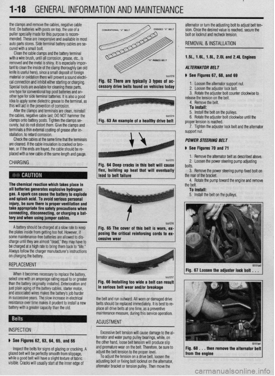
Fig. 62 mere are typically 3 types of ac-
cessory drive belts found on vehicles today 1. Loosen the alternator support nut.
2. Loosen the adjuster lock bolt.
3. Rotate the adjuster bolt counter clockwise to
I .I , . . . * . .
I Tn i”et*ll* Fig. 62 There are typically 3 types of ac-
Fig. 64 Deep cracks in this belt will cause
flex, building up heat that will eventually 11, 1.8L, 2.OL and 2.4L Engines
cal connection and inhibit either starting or charging.
Special tools are available for cleaning these parts,
one type for conventional top post batteries and an-
other type for side terminal batterin, I+ if QI@* 3 nnnd
idea to apply some dielectric grr
this will aid in the prevention of ,,vIIuaIUII.
After the clamps and terminals are clean, reinstall 1.5L, 1.6
AL TERNA TOR BE1 T
e See Figures 67,68, and 69
1. Loosen the alternator support nut.
2. Loosen the adjuster lock bolt.
3. Rotate the adjuster bolt counter clockwise to
release the tension on the belt.
4. Remove the belt.
To install:
5. Install the belt on the pulleys.
6. Rotate the adjuster bolt clockwise until the
proper tension is reached.
7. Tighten the adjuster lock bolt and the alternator
support nut.
POWER STEERING BELT
8 See Figures 70 and 71
1. Remove the alternator belt as described above.
2. Loosen the power steering pump adjusting
bolts.
3. Remove the power steering oumo fixed bolt on
R Rntatn the cxiillrtm hnit A&+,& until the r -r- .- .- ._.. ._ .______
7. Tighten the adjuster lock bolt and the alternator
support nut.
POWER STEERING BELT
1 ..“‘.I ““..Y...Y up II”“. ..IU. ..m.*
1 lead to belt failure V.
I
I
The chemical reaction which takes place in - 1 the rear of the bracket.
4. Rotate the pump toward the engine and remove
the belt.
all batteries generates explosive hydrogen
gas. A spark can cause the battery to explode
and splash acid. To avoid serious personal
injury, be sure there is proper ventilation and
take appropriate fire safety precautions when
connecting, disconnecting, or charging a bat-
tery and when using jumper cables. To fnstall:
5. Install the belt on the pulleys.
A battery should be charged at a slow rate to keep
the plates inside from getting too hot. However, if
some maintenance-free batteries are allowed to dis-
charge until they are almost “dead,” they may have to
be charged at a high rate to bring them back to “life.”
Always follow the charger manufacturers instructions
on charging the battery. 85 The cover of this belt ex-
Fig. is worn,
REPLACEMENT
When it becomes necessary to reolace thn haeoN
‘” yyL’“‘J’ I or oreMer
select one with an amperage rating equal tc .
a ----
than the battery originally installed. Deterioration and
just plain aging of the battery cables, starter motor,
and associated wires makes the battery’s job harder
in successive years. The slow increase in electrical
resistance over time makes it prudent to install a new
battery with a greater capacity than the old. 1 Fig. 67 Loosen the adjuster lock bolt . . .
I ‘-
I -. -_ tm1217 Fig. 66 Installing too wide a belt can resylt
in serious belt wear and/or breakage
the belt and run outward. All worn or damaged drive
belts should be replaced immediately. It is best to re-
place all drive belts at one time, as a preventive
uring this service operation. maintenance measure, d
- ADJUSTMENT : *
INSPECTION Excessive belt tension will cause damage to the al-
e See Figures 62, 83, 64, 65, and 88
Inspect the belts for signs of glazing or cracking. A
glazed belt will be perfectly smooth from slippage,
while a good belt will have a slight texture of fabric
visible. Cracks will usually start at the inner edge of pulley bearings, while, on
It tension will
Droduce slin ternator and water pump
the other hand, loose be
r ------ r
and premature wear on the belt. Therefore, be sure to
adjust the belt tension to the proper level.
To
adjust the tension ’ ’ ’ ” ’ ‘* adjusting bolt or fixing b
alternator bracket or tens on a onve Den. loosen me I Fig. 68 . . . then
from the engine remove the alternator
bolt locknut on the alternator,
iion pulley. Then move the
Page 22 of 408
t
GENERALINFORMATIONAND MAINTENANCE l-23
gap increases, the plug’s voltage requirement also in-
creases. It requires a greater voltage to jump the the spark plug counterclockwise to loosen and re-
move the spark plug from the bore.
wider gap and about &o to three times as much volt-
age to fire the plug at high speeds than at idle. The
improved air/fuel ratio control of modern fuel injec-
tion combined with the higher voltage output of mod- Be sure not to use a flexible extension on the place. The click may be felt or heard, then gently pull
ern ignition systems will often allow an engine to run socket. Use of a flexible extension may allow back on the boot to assure proper contact.
.___. . _
significantly longer on a set of standard spark plugs, a shear force to be agptf’ ea to me plug.
A 12. On the 3.OL fSOHC and DOHC) and 3.5L en-
LL_ _I___ -u I_ IL-
but keep in mind that efficiency will drop as the gap shear force could break tne pug on III me
tion 3 for the installation procedure.
widens (along with fuel economy and power). cylinder head, leading to costly and frustrat-
13. If equipped, install the center cover.
When you’re removing spark plugs, work on one ing repairs.
at a time. Don’t start by removing the plug wires all at
once, because, unless you number them, they may To install:
INSPECTION & GAPPING
11. Apply a small amount of silicone dielectric
compound to the end of the spark plug lead or inside
the spark plug boot to prevent sticking, then install
the boot to the spark plug and push until it clicks into
gines, install the upper intake manifold. Refer to Sec-
,,Y” ..1111 uy”’ 1 the neaative bat&v cable and if become mixed up. Take a minute before you begin
and number the wrrpc with +sne
1. Disconnect. ~~.~
--..-., -..-.-, -..-
thevehicle has been run recently, allow the engine to
thoroughly cool.
2. If equipped, remove the center cover.
3. On the 3.OL (SOHC and DOHC) and 3.5L en-
gines, the upper intake manifold must be removed to
access the rear spark plugs. Refer to Section 3 for the
removal procedure.
4. Carefully twist the spark plug wire boot to
loosen it, then pull upward and remove the boot from
the plug. Be sure to pull on the boot and not on the
wire, otherwise the connector located inside the boot
may become separated.
5. Using compressed air, blow any water or de-
bris from the spark plug well to assure that no harm-
ful contaminants are allowed to enter the combustion
chamber when the spark plug is removed. If com-
pressed air is not available, use a raa or a brush to must be replaced.
Check the plugs for deposits and wear, If they are 7. Inspect the spark plug boot for tears or dam-
age. If.a damaged boot is found, the spark plug wire
8. Using a wire feelergauge, check and adjust
the spark plug gap. When using a gauge, the proper
size should pass between the electrodes with a slight
drag. The next larger size should not be able to pass
while the next smaller size should pass freely.
9. Carefully thread the plug into the bore by
hand. If resistance is felt before the plug is almost
completely threaded, back the plug out and begin
threading again. In small, hard to reach areas, an old
spark plug wire and boot could be used as a thread-
ing tool. The boot will hold the plug while you twist
the end of the wire and the wire is supple enough to
twist before it would allow the plug to crossthread.
Do not use the spark plug sock?
l -- K-rrA tha nhme Alwmm rarntdlv thw GL I” IlllGa”
the possibility of crossthreading and damag- lad the plug
. ..Y f..“YY. rn”Y,‘““mY*“.‘, .I**” by hand or using an old plug wire to prevent
ing the cylinder head bore.
10. Carefully tighten the spark plug. If the plug
you are installing is equipped with a crush washer,
seat the plug, then tighten about I/, turn to crush the
washer. If you are installing a tapered seat plug,
tighten the plug to specifications provided by the ve-
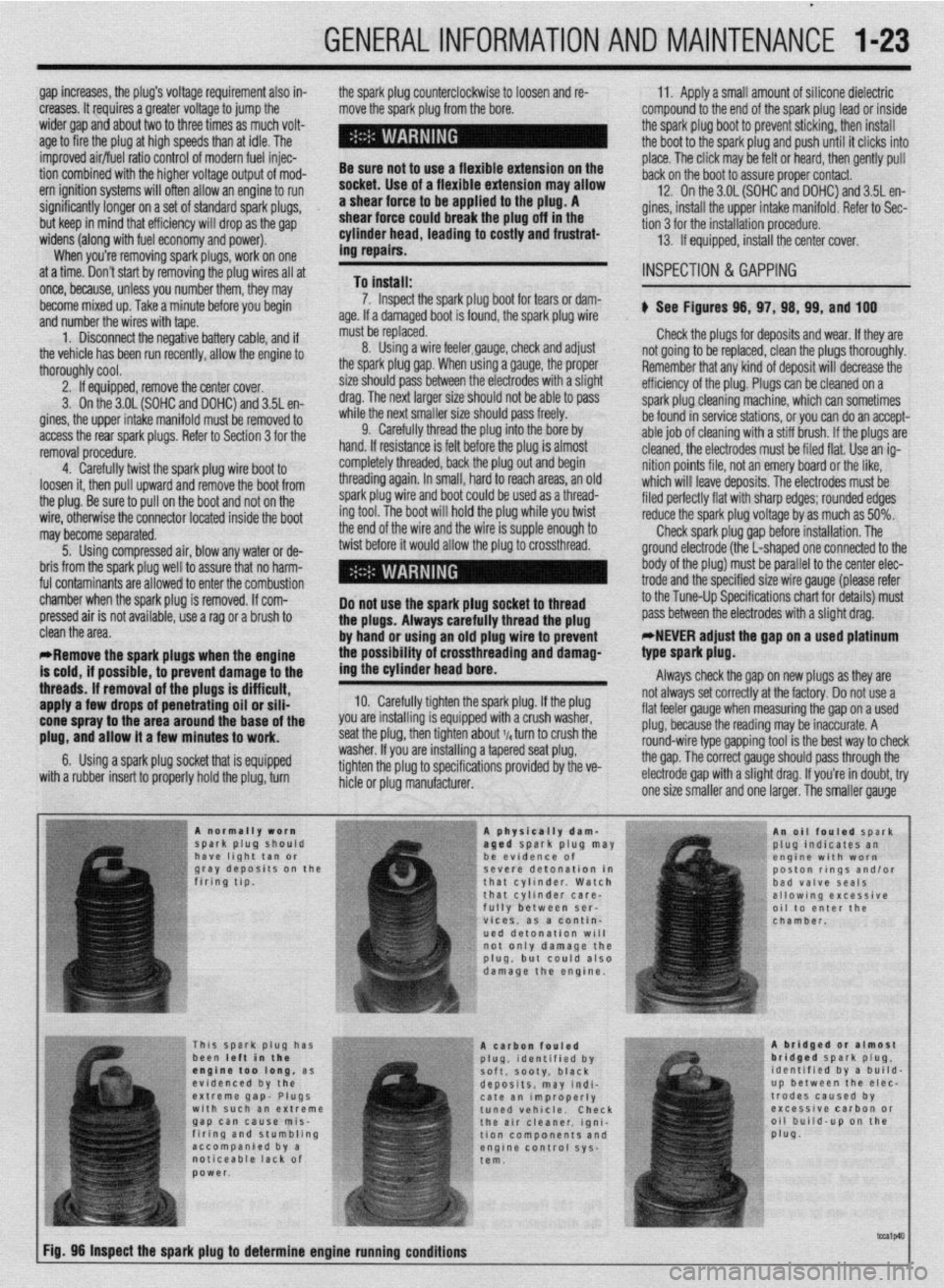
hicle or plug manufacturer. b See Figures 98, 97, 98, 99, and 100
not going to be replaced, clean the plugs thoroughly.
Remember that any kind of deposit will decrease the
efficiency of the plug. Plugs can be cleaned on a
spark plug cleaning machine, which can sometimes
be found in service stations, or you can do an accept-
able job of cleaning with a stiff brush. If the plugs are’
cleaned, the electrodes must be filed flat. Use an ig-
nition points file, not an emery board or the like,
which will leave deposits. The electrodes must be
filed perfectly flat with sharp edges; rounded edges
reduce the spark plug voltage by as much as 50%.
Check spark plug gap before installation. The
ground electrode (the L-shaped one connected to the
body of the plug) must be parallel to the center elec-
trode and the specified size wire gauge (please refer
to the Tune-Up Specifications chart for details) must
pass between the electrodes with a slight drag:
*,NEVER adjust the gap on a used platinum
. clean the area.
*Remove the spark plugs when the engine
is cold, if possible, to prevent damage to the
threads. If removal of the plugs is difficult,
apply a few drops of penetrating oil or sili-
cone spray to the area around the base of the
plug, and allow it a few minutes to work.
6. Using a spark plug socket that is equipped
with a rubber insert to properly hold the plug, turn type spark plug.
Always check the gap on new plugs as they are
not always set correctly at the factory. Do not use a
flat feeler gauge when measuring the gap on a used
plug, because the reading may be inaccurate. A
round-wire type gapping tool is the best way to check
the gap. The correct gauge should pass through the
electrode gap with a slight drag. If you’re in doubt, try
one size smaller and one laraer. The smaller aauqe
Page 25 of 408
.
1-26 GENERALINFORMATIONAND MAINTENANCE
TDC of the compression stroke. If this happens, the
piston WIII be at the beginning of the power stroke
just as the compressed and ignited air/fuel mixture
forces the piston down and turns the crankshaft. Be-
cause it takes a fraction of a second for the spark
plug to ignite the mixture in the cylinder, the spark
plug must fire a little before the piston reaches TDC.
Otherwise, the mixture will not be completely ignited
as the piston passes TDC and the full power of the
explosion will not be used by the engine.
The timing measurement is given in degrees of
crankshaft rotation before the piston reaches TDC
(BTDC). If the setting for the ignition timing is 10”
BTDC, each spark plug must fire 10 degrees before
each piston reaches TDC. This only holds true, how-
ever, when the engine is at idle speed. The combus-
tion process must be complete by 23”ATDC to main-
tain proper engine performance, fuel mileage, and
low emissions.
As the engine speed increases, the pistons go
faster. The spark plugs have to ignite the fuel even
sooner if it IS to be completely ignited when the pis-
ton reaches TDC. If the ignition is set too far ad-
vanced (BTDC), the ignition and expansion of the fuel
in the cylinder wtll occur too soon and tend to force
the piston down while it is still traveling up. Thus
causes pre ignition or “knockmg and pinging”. If the
ignition spark is set too far retarded, or after TDC
(ATDC), the piston will have already started on its
way down when the fuel is ignited. The piston will be
forced down for only a portion of its travel, resulting
in poor engine performance and lack of power.
Timing marks or scales can be found on the rim of
the crankshaft pulley and the timing cover. The marks
on the pulley correspond to the posrtion of the piston
in the No. 1 cylinder. A stroboscopic (dynamic) tim-
ing light is hooked onto the No. 1 cylinder spark plug
wrre. Every time the spark plug fires, the timing light
flashes. By aiming the light at the timing marks while
the engine is running, the exact position of the piston
within the cylinder can be easily read (the flash of
light makes the mark on the pulley appear to be
standing still). Proper timing is indicated when the
mark and scale are in specified alignment.
When checking timing with the engine run-
ning, take care not to get the timing light
wires tangled in the tan blades and/or drive
belts.
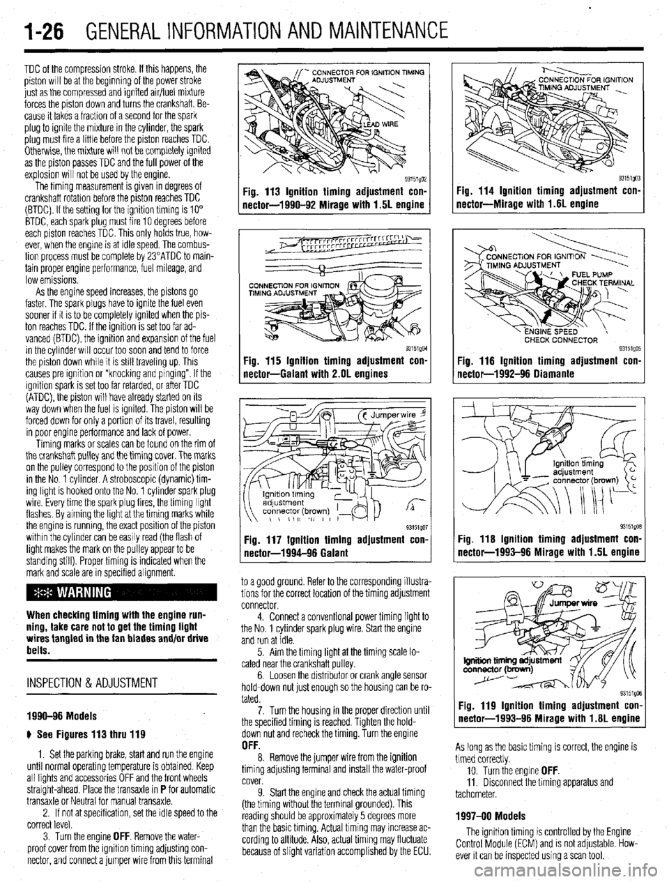
INSPECTION &ADJUSTMENT
1990-96 Models
e See Figures 113 thru 119
1. Set the parking brake, start and run the engine
until normal operating temperature is obtained. Keep
all lights and accessories OFF and the front wheels
straight-ahead. Place the transaxle in
P for automatic
transaxle or Neutral for manual transaxle.
2. If not at specification, set the idle speed to the
correct level.
3. Turn the engine
OFF. Remove the water-
proof cover from the igmtion timing adjusting con-
nector, and connect a jumper wire from this terminal
Fig. 113 Ignition timing adjustment con-
nector-1990-92 Mirage with 1.5L engine
93151QM Fig. 115 Ignition timing adjustment con-
nectar-Galant with 2.OL engines
93151QO1 Fig. 117 Ignition timing adjustment con.
nectar-1994-96 Galant
to a good ground. Refer to the corresponding illustra-
tions for the correct location of the timing adjustment
connector.
4. Connect a conventional power timing light to
the No. 1 cylinder spark plug wire. Start the engine
and run at idle.
5. Aim the timing light at the timing scale lo-
cated near the crankshaft pulley.
6. Loosen the distributor or crank angle sensor
hold-down nut just enough so the housing can be ro-
tated.
7. Turn the housing in the proper direction until
the specified timing is reached. Tighten the hold-
down nut and recheck the timing. Turn the engine
OFF. 8. Remove the jumper wire from the ignition
timing adjusting terminal and install the water-proof
cover.
9. Start the engine and check the actual timing
(the timing without the terminal grounded). This
reading should be approximately 5 degrees more
than the basic timing. Actual timing may increase ac-
cording to altitude. Also, actual timing may fluctuate
because of slight variation accomplished by the ECU.
Fig. 114 Ignition timing adjustment con-
nectar-Miracle with 1.6L enaine
CHECK CONNECTOR 93151QO! Fig. 116 Ignition timing adjustment con.
nectar-1992-96 Oiamante
93151gOB Fig. 116 Ignition timing adjustment con-
nector-1993-96 Mirage with 1.5L engine
Fig. 119 Ignition timing adjustment con-
nector-1993-96 Mirage with 1.6L engine
As long as the basic timing is correct, the engine is
timed correctly.
10. Turn the engine
OFF. 11. Disconnect the timing apparatus and
tachometer.
1997-00 Models
The ignition timing is controlled by the Engine
Control Module (ECM) and is not adjustable. How-
ever it can be inspected using a scan tool.
Page 43 of 408
1-44 GENERALINFORMATIONAND MAINTENANCE
INTERIOR CLEANING
Upholstery
Fabric can usually be cleaned with soapy water or
a proper detergent. For more difficult spots caused by
oil, ice cream, soda, etc., use a fabric cleaner avail-
able at most parts stores. Be sure when purchasing
the cleaner to read the label to ensure it is safe to use
on your type of fabric. A safe method of testing the
cleaner is to apply a small amount to an area usually
unseen, such as under a seat, or other areas. Wart a
while, perhaps even a day to check the spot for fad-
ing, discoloring, etc., as some cleaners will only
cause these problems after they have dried
Leather upholstery requrres special care, it can be
cleaned with a mild soap and a soft cloth. It is recom-
mended that a special leather cleaner be used to
clean but also treat the leather surfaces in your vehi-
cle. Leather surfaces can age quickly and can crack if
not properly taken care of, so it is vital that the leather
surfaces be maintained.
Floor Mats and Carpet
The floor mats and carpet should be vacuumed or
brushed regularly. They can be cleaned with a mild
soap and water. Special cleaners are available to
clean the carpeted surfaces of your vehicle, but take
care in choosing them, and again it is best to test
them in a usually unseen spot.
Dashboard, Console, Door Panels, Etc.
The dashboard, console, door panels, and other
plastic, vinyl, or wood surfaces can be cleaned using
a mild soap and water. Caution must be taken to keep
water out of electronic accessories and controls to
avoid shorts or ruining the components Again spe-
cial cleaners are available to clean these surfaces, as
with other cleaners care must taken in purchasmg
and using such cleaners.
There are protectants available which can treat the
various surfaces in your car giving them a “shiny new
look”, however some of these protectants can cause
more harm than good in the long run. The shine that
is placed on your dashboard attracts sunlight accel-
erating the aging, fading and possibly even cracking
the surfaces. These protectants also attract more dust
to stick to the surfaces they treat, Increasing the cleaning you must do to maintain the appearance of
your vehicle. Personal discretion is advised here.
On most models covered by this manual, the
wheel bearmgs used are sealed units and do not re-
quire routine maintenance. However on some Galant
and Mirage models, the rear wheel bearing do require
periodic repacking. For removal and installation in-
structions, please refer to Section 7 (for rear bear-
ings) or Section 8 (for front bearings).
REPACKING
*Sodium based grease is not compatible
with lithium based grease. Read the package
labels and be careful not to mix the two
types. If there is any doubt as to the type of
grease used, completely clean the old
grease from the bearing and hub before re-
placing.
Before handling the bearings, there are a few
things that you should remember to do and not to do.
DO the following: l Remove all outside dirt from the housing be-
fore exposing the bearing.
l Treat a used bearing as gently as you would a
new one.
l Work with clean tools in clean surroundings. l Use clean, dry gloves, or at least clean, dry
hands.
l Clean solvents and flushing fluids are a must. l Use clean paper when laying out the bearings
to dry.
l Protect drsassembled bearings from rust and
dirt. Cover them up.
l Use clean, lint-free rags to wipe the bearings. l Keep the bearings in oil-proof paper when they
are to be stored or are not in use.
l Clean the inside of the housing before replac-
ing the bearin
Do NOT do he followino: El, l Do not work in dirty sirroundings. l Do not use dirty, chipped or damaged tools. l Do not work on wooden work benches or use
wooden mallets.
l Do not handle bearings with dirty or moist
hands.
l Do not use gasoline for cleaning. Use a safe
solvent.
l Do not spin dry bearings with compressed air.
They will be damaged.
l Do not use cotton waste or dirty cloths to wipe
bearings.
l Do not scratch or nick bearing surfaces. l Do not allow the bearina to come in contact
” with dirt or rust at any time.
The rear wheel bearinas on some Galant and Mi-
rage models require periodic maintenance. A pre-
mium high melting point grease meeting Grade
Multipurpose Grease NLGI Grade #2 or equivalent
must be used. Long fiber type greases must not be
used. This service is recommended every 30,000
miles (48,000 km).
*For information on Wheel Bearing removal
and installation, refer to Section 7 of this
manual.
1. Remove the wheel bearing.
2. Clean all parts in a non-flammable solvent and
let them air dry.
*Only use lint-free rags to dry the bearings.
Never spin-dry a bearing with compressed
air, as this will damage the rollers.
3. Check for excessive wear and damage. Replace
the bearing as necessary.
*Packina wheel bearinos with arease is
best accomplished by u&g a wheel bearing
packer (available at most automotive parts
stores).
4. If a wheel bearing packer is not available, the
bearings may be packed by hand.
a. Place a “healthy’ glob of grease in the
palm of one hand.
b. Force the edge of the bearing into the
grease so that the grease fills the space between
the rollers and the bearing cage.
c. Keep rotating the bearing while continuing
to push the grease through.
d. Continue until the grease is forced out the
other side of the bearing.
5. Place the packed bearing on a clean surface
and cover it until it is time for installation.
6. Install the wheel bearing.
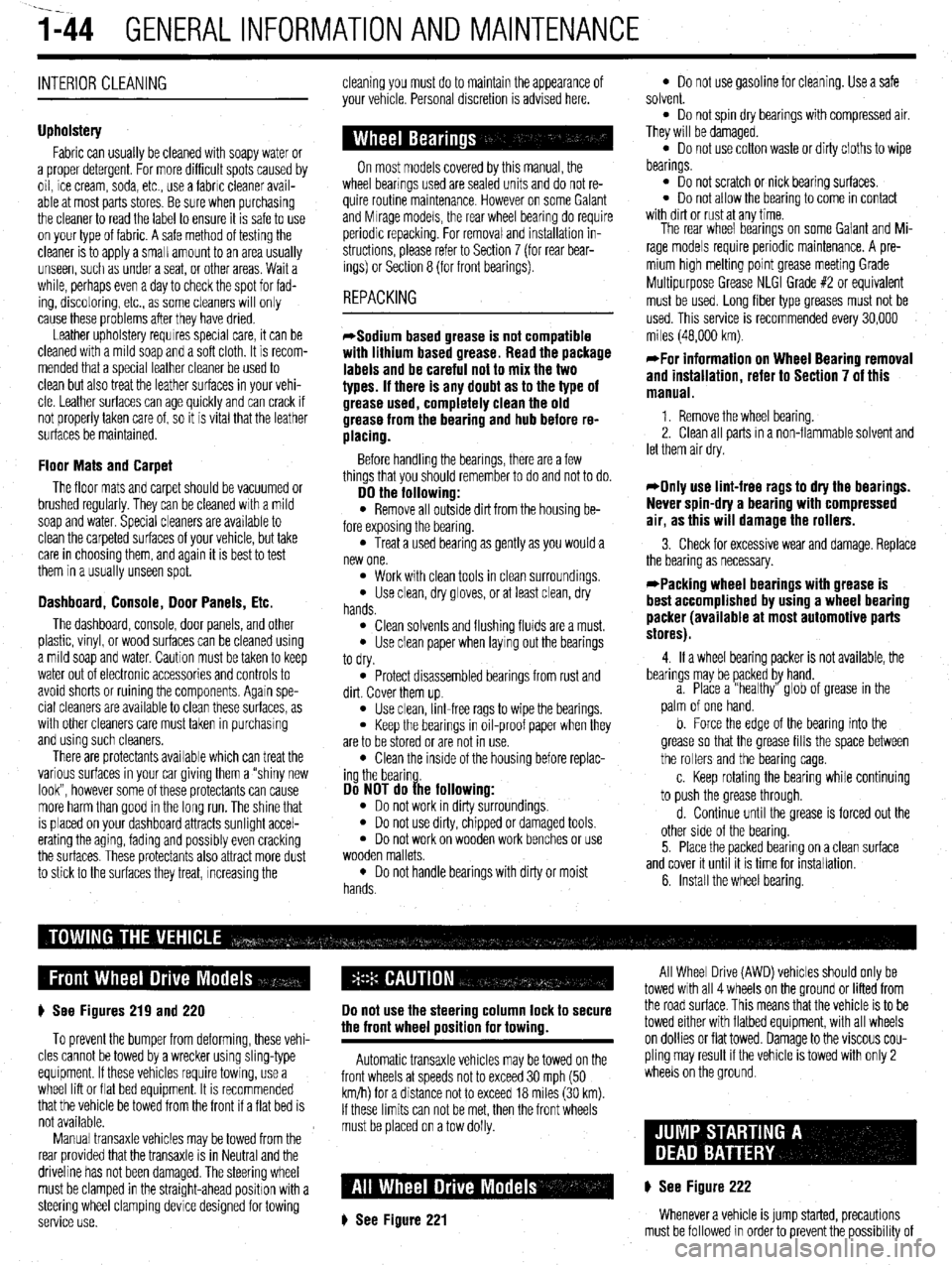
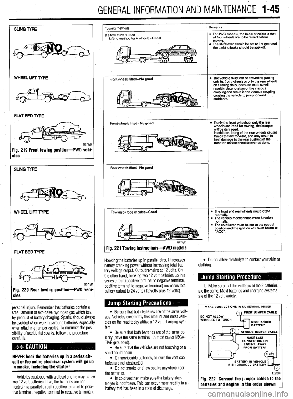
# See Figures 219 and 220
To prevent the bumper from deforming, these vehi-
cles cannot be towed by a wrecker using sling-type
equipment. If these vehicles require towing, use a
wheel lift or flat bed equipment. It is recommended
that the vehicle be towed from the front If a flat bed is
not available.
Manual transaxle vehicles may be towed from the
rear provided that the transaxle is in Neutral and the
driveline has not been damaged. The steering wheel
must be clamped in the straight-ahead positron with a
steering wheel clamping device designed for towing
service use.
Do not use the steering column lock to secure
the front wheel uosition for towina.
Automatic transaxle vehicles may be towed on the
front wheels at speeds not to exceed 30 mph (50
km/h) for a distance not to exceed 18 miles (30 km).
If these limits can not be met, then the front wheels
must be placed on a tow dolly.
# See Figure 221
All Wheel Drive (AWD) vehicles should only be
towed with all 4 wheels on the ground or lifted from
the road surface. This means that the vehicle is to be
towed either with flatbed equipment, with all wheels
on dollies or flat towed. Damage to the viscous cou-
pling may result if the vehicle is towed with only 2
wheels on the ground.
p See Figure 222
Whenever a vehicle is jump started, precautions
must be followed In order to prevent the possibility of
Page 44 of 408
GENERALINFORMATIONAND MAINTENANCE 1-45
SLING TYPE
WHEEL LIFT TYPE
cles
SUNG TYPE
WHEEL LIFT TYPE
FLAT BED TYPE
Fig. 220 Rear towing position-FWD vehi
cles
personal injury. Remember that batteries contain a
small amount of explosive hydrogen gas which is a
by-product of battery charging. Sparks should always
be avoided when working around batteries, especially
when attaching jumper cables. To minimize the pos-
sibility of accidental sparks, follow the procedure
carefully.
NEVER hook the batteries up in a series cir-
cuit or the entire electrical system will go up
in smoke. includino the starter!
Vehicles equipped with a diesel engine may utilize
two 12 volt batteries. If so, the batteries are con-
nected in a parallel circuit (positive terminal to posi-
tive terminal, negative terminal to negative terminal).
owrng methods
a tow truck IS used
Lrftrng method for 4 wheels-Good
Front wheels lifted-No good
Front wheels lifted-No good
Rear wheels lifted-No good
Towing by rope or cable-Good
e9571g92 qemarks
. For4WD models, the basic principle is that
all four wheels are to be rarsed before
towing.
. The shift lever should be set to 1 st gear and
the parking brake should be applied.
l The vehicle must not be towed by tofacing
only its front wheels or only the rear wheels
on a rollino dollv, because to do so will
result in d&e&ration of the visfx~s
coupling and result in the viscous coupling
causing the vehicle to jump forward
suddenly.
l If only the front wheels or only the rear
wheels are lifted for towing, the bumper
wrll bedamyd.
In addrtron. II trng of the rear wheels causes
the or1 to flow forward. and may result in
heat damage to the rear bushing of the
transfer, and so should never be done.
l The front and rear wheels must rotate
normally.
l The various mechanisms must function
normally.
l The shift lever must be set to the neutral
~Asi&n and the ignition key must be set to
Fig. 221 Towing instructions-AWD models
Hooking the batteries up in parallel circuit increases
battery cranking power without increasing total bat-
tery voltage output. Output remains at 12 volts. On
the other hand, hooking two 12 volt batteries up in a
series circuit (positive terminal to negative terminal,
positive terminal to negative terminal) increases total
battery output to 24 volts (12 volts plus 12 volts).
l Be sure that both batteries are of the same volt-
age. Vehicles covered by this manual and most vehi-
cles on the road today utilize a 12 volt charging sys-
tem.
l Be sure that both batteries are of the same po-
larity (have the same terminal, in most cases NEGA-
TIVE grounded).
l Be sure that the vehicles are not touching or a
short could occur.
l On serviceable batteries, be sure the vent cap
holes are not obstructed.
l Do not smoke or allow sparks anywhere near
the batteries.
l In cold weather, make sure the battery elec-
trolyte is not frozen, This can occur more readily in a
battery that has been in a state of discharge.
l Do not allow electrolyte to contact your skin or
clothing.
1. Make sure that the voltages of the 2 batteries
are the same. Most batteries and charging systems
are of the 12 volt variety.
MAKE CONNECTIONS IN NUMERICAL ORDER
A FIRST JUMPER CABLE
WITH CHARGED BATTERY
-
lccslQ?,Q
Fig. 222 Connect the jumper cables to the
batteries and engine in the order shown
Page 45 of 408
.
I-46 GENERALINFORMATIONAND MAINTENANCE
2. Pull the jumping vehicle (with the good bat-
tery) into a position so the jumper cables can reach
the dead battery and that vehicle’s engine. Make sure
that the vehicles do NOT touch.
3. Place the transmissions/transaxles of both ve-
hicles in Neutral (MT) or P (AT), as applicable, then
firmly set their parking brakes.
*ff necessary for safety reasons, the hazard
lights on both vehicles may be operated
throughout the entire procedure without sig-
nificantiy increasing the diff icuity of jumping
the dead battery.
4. Turn all lights and accessories OFF on both
vehicles. Make sure the ignition switches on both ve-
hicles are turned to the OFF position.
5. Cover the battery cell caps with a rag, but do
not cover the terminals.
6. Make sure the terminals on both batteries are
clean and free of corrosion or proper electrical con-
nection will be impeded. If necessary, clean the bat-
tery terminals before proceeding.
7. Identify the positive (+) and negative (-) termi-
nals on both batteries.
8. Connect the first jumper cable to the positive
(t) terminal of the dead battery, then connect the
other end of that cable to the positive (t) terminal of
the booster (good) battery.
9. Connect one end of the other jumper cable to
the negative (−) terminal on the booster bat-
tery and the final cable clamp to an engine bolt head,
alternator bracket or other solid, metallic point on the
engine with the dead battery. Try to pick a ground on
the engine that is positioned away from the battery in
order to minimize the possibility of the 2 clamps
touching should one loosen during the procedure.
DO NOT connect this clamp to the negative (-) termi-
nal of the bad battery. cable on the donor battery. Disconnect the positive
cable from the donor battery and finally, disconnect
the positive cable from the formerly dead battery. Be
careful when disconnecting the cables from the posi-
tive terminals not to allow the alligator clips to touch
any metal on either vehicle or a short and sparks will
occur.
I
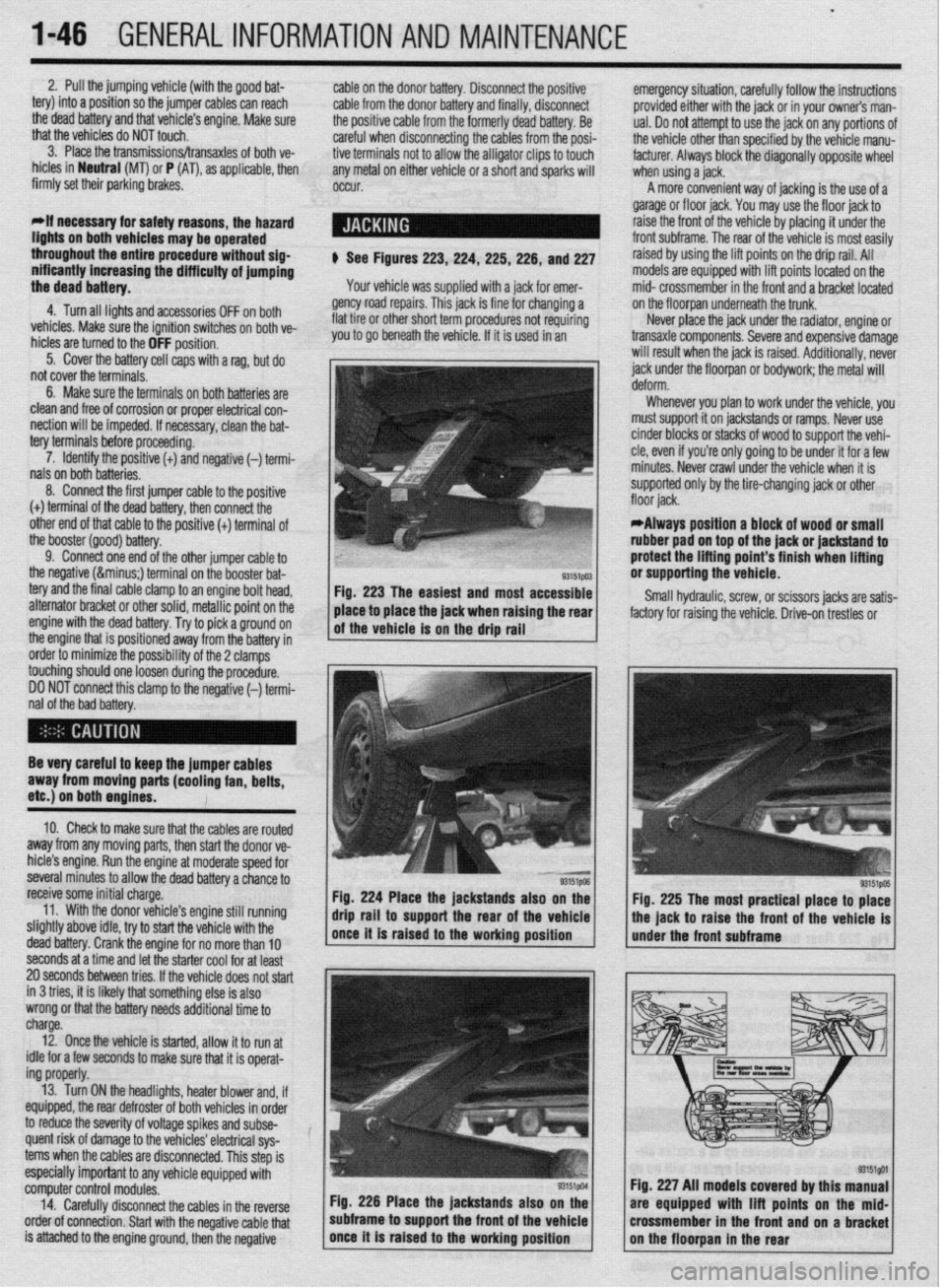
$ See Figures 223,224, 225,226, and 227
Your vehicle was supplied with a jack for emer-
gency road repairs. This jack is fine for changing a
flat tire or other short term procedures not requiring
you to go beneath the vehicle. If it is used in an emergency situation, carefully follow the instructions
provided either with the jack or in your owners man-
ual. Do not attempt to use the jack on any portions of
the vehicle other than specified by the vehicle manu-
facturer. Always block the diagonally opposite wheel
when using a jack.
A more convenient way of jacking is the use of a
garage or floor jack. You may use the floor jack to
raise the front of the vehicle by placing it under the
front subframe. The rear of the vehicle is most easily
raised by using the lift points on the drip rail. All
models are equipped with lift points located on the
mid- crossmember in the front and a bracket located
on the floorpan underneath the trunk.
Never place the jack under the radiator, engine or
transaxle components. Severe and expensive damage
will result when the jack is raised. Additionally, never
jack under the floorpan or
bodywork; the
metal will
Whenever you plan to work under the vehicle, you
must support it on jackstands or ramps. Never use
cinder blocks or stacks of wood to support the vehi-
cle, even if you’re only going to be under it for a few
minutes. Never crawl under the vehicle when it is
supported only by the tire-changing jack or other
*Always position a block of wood or small
rubber pad on top of the jack or jackstand to
protect the lifting point’s finish when lifting
or supporting the vehicle.
Small hydraulic, screw, or scissors jacks are satis-
factory for raising the vehicle. Drive-on trestles or
Be very careful to keep the jumper cables
away from moving parts (cooling fan, belts,
etc.) on both engines.
10. Check to make sure that the cables are routed
away from any moving parts, then start the donor ve-
hicle’s engine. Run the engine at moderate speed for
several minutes to allow the dead battery a chance to
receive some initial charge.
11. With the donor vehicle’s engine still running
slightly above idle, try to start the vehicle with the
dead battery. Crank the engine for no more than 10 &stands also on the
Fig. 225 The most practical place to place
front of the vehicle is
seconds at a time and let the starter cool for at least
20 seconds between tries. If the vehicle does not start
in 3 tries, it is likely thatsomething else is also
wrong or that the battery needs additional time to
charge.
12. Once the vehicle is started, allow it to run at
idle for a few seconds to make sure that it is operat-
ing properly.
13. Turn ON the headlights, heater blower and, if
equipped, the rear defroster of both vehicles in order
to reduce the severity of voltage spikes and subse-
quent risk of damage to the vehicles’ electrical sys-
tems when the cables are disconnected. This step is
especially important to any vehicle equipped with
computer control modules.
14. Carefully disconnect the cables in the’reverse
order of connection. Start with the negative cable that
is attached to the engine ground, then the negative Fig. 226 Place the jackstands also
subframe to support the front of the Fig. 227 All models covered by this
are equipped with lift points on t
crossmember in the front and on a
Page 49 of 408
.~ P.X I_ - “, .- I .-., IS ” .~.I .r
2-2 ENGINE ELECTRICAL
nn
ity and trouble: shooting electrical circuits,
please refer to Section 6 of this manual.
I
The ignition system on the 1.5L, 1993-96 1.8L,
2.OL SOHC, 1994-98 2.4L SOHC, 3.OL SOHC, and
3.5L engines uses a pointless type distributor, whose
advance mechanism is controlled by the Engine Con-
trol Unit (ECU). On the 1.5L, 1.8L, 2.4L and 3.5L en-
gines, the distributor houses a built in ignition coil
and ignition power transistor. The 2.8L SOHC and
3.OL SOHC engines utilize a separate coil and tran-
sister assemblv.
When the ignition switch is turned ON, battery
voltage is applied to the ignition coil primary winding.
As the shaft of the distributor rotates, signals are
transmitted from the oowertrain control module to the
9105zp11 Fig. 1 This spark tester looks iust like a
Fiu. 2 This spark tester has an adjustable
spark plug, attach the clip to ground and air-gap for measuring spark strength and
crank the engine to check for spark testing different voltage ignition systems
.
ignition power trar rsistor. These signals activate the
power transistor to cause ignition coil primary wind-
ing current flow from the ignition coil negative termi-
nal through the power transistor to ground repeatedly.
This interruption induces high voltage in the ignition
coil secondarv windinas, which is diverted throuah
the distributor, spark plug cable and spark plug 6
ground, thus causing ignition in each cylinder.
I
SECONDARYSPARKTEST l;h.4-
! ,L ".~
'$ >,%
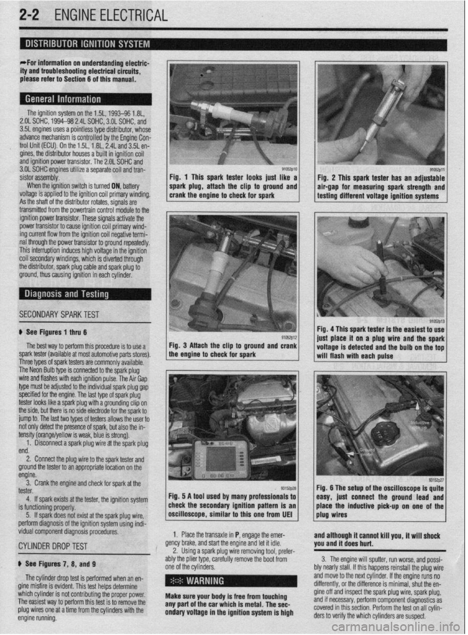
If See Figures 1 thru 6
91rJszp12 Fig. 4 This spark tester is the easiest to use
iust alace it on a plug wire and the spark
The best way to perform this procedure is to use a Fig. 3 Attach the clip to ground and crank
spark tester (available at most automotive parts stores). the engine to check for spark
I I voltage is detected and the bulb on the tof
-. will flash with each pulse
I nree types ot spark testers are commonly available.
The Neon Bulb type is connected to the spark plug
wire and flashes with each ignition pulse. The Air Gap
type must be adjusted to the individual spark plug gap
specified for the engine. The last type of spark plug
tester looks like a spark plug with a grounding clip on
the side, but there is no side electrode for the spark to
jump to. The last two types of testers allows the user to
not only detect the presence of spark, but also the in-
tensity (orange/yellow is weak, blue is strong).
1. Disconnect a spark plug wire at the spark plug
end.
2. Connect the plug wire to the spark tester and
ground the tester to an appropriate location on the
engine.
3. Crank the engine and check for spark at the
tester.
4. If spark exists at the tester, the ignition system
is functioning properly.
5. If spark does not exist at the spark plug wire,
perform diagnosis of the ignition system using indi-
vidual component diagnosis procedures,
CYLINDER DROPTEST
p See Figures 7, 8, and 9
The cylinder drop test is performed when an en-
gine misfire is evident. This test helps determine
which cylinder is not contributing the proper power.
The easiest way to perform this test is to remove the
plug wires one at a time from the cylinders with the
engine running. 1. Place the transaxle in P, engage the emer-
gency brake, and start the engine and let it idle.
2. Using a spark plug wire removing tool, prefer-
ably the plier type, carefully remove the boot from
one of the cylinders.
i ’
Make sure your body is free from touching
any part of the car which is metal. The sec-
ondary voltage in the ignition system is high and although it cannot kill you, it will shock
you and it does hurt.
3. The engine will sputter, run worse, and possi-
bly nearly stall. If this happens reinstall the plug wire
and move to the next cylinder. If the engine runs no
differently, or the difference is minimal, shut the en-
gine off and inspect the spark plug wire, spark plug,
and if necessary, perform component diagnostics as
covered in this section. Perform the test on all cylin-
ders to verify the which cylinders are suspect.
Page 171 of 408
4-28 DRIVEABILITYAND EMISSIONS CONTROLS
Fig. 88 Plug the scan tool into the DLC un-
Fig. 89 Follow the directions on the scan
der the driver’s side of the instrument panel
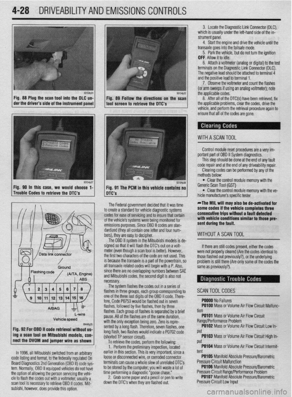
tool screen to retrieve the DTC’s 3. Locate the Diagnostic Link Connector (DLC),
which is usually under the left-hand side of the in-
strument panel.
4. Start the engine and drive the vehicle until the
transaxle goes into the failsafe mode.
5. Park the vehicle, but do not turn the ignition
OFF. Allow it to idle.
6. Attach a voltmeter (analog or digital) to the test
terminals on the Diagnostic Link Connector (DLC).
The negative lead should be attached to terminal 4
and the positive lead to terminal 1.
7. Observe the voltmeter and count the flashes
(or arm sweeps if using an analog voltmeter); note
the applicable codes.
- 8. After all of the DTC(s) have been retrieved, fix
the applicable problems, clear the codes, drive the
vehicle, and perform the retrieval procedure again to
ensure that all of the codes are gone.
WITHASCANTOOL
Control module reset procedures are a very im-
portant part of OBD II System diaqnostics.
This step should be done at the end of any fault
code repair and at the end of any driveability repair.
Clearing codes can be performed by any of the
Fig. 90 in this case, we would choor- A ’ ma*-. . . * .
Trouble Codes to retrieve the DTC’s
-.- -
A mere mar
. . methods below: l Clear the control module memory with the
se l-
I I ng. vi me rtim In mts venicie contains no Generic Scan Tool (GST) l DTC’S Clear the control module memory with the ve-
L’-‘m iufacturer’s specific tester
The Federal government decided that it was time
to create a standard for vehicle diagnostic systems
codes for ease of servicing and to insure that certain
of the vehicle’s systems were being monitored for
emissions purposes. Since OBD II codes are stan-
dardized (they all contain one letter and four num-
bers), they are easy to decipher.
The OBD II system in the Mitsubishi models is de-
signed so that it will flash the DTC’s out on a volt-
meter (even though a scan tool is better). However,
the first two characters of the code are not used. This
is because the transaxle is a part of the powertrain, so
all transaxle related codes will begin with a P. Also, *The MIL will may also be de-activated for
some codes if the vehicle completes three
consecutive trips without a fault detected
with vehicle conditions similar to those pre-
sent during the fault.
WITHOUTASCAN TOOL
If there are still codes p
resent, either the codes
were not properly cleared f
:Are the codes identical to
those flashed out previous
I$‘), or the underlying
problem is still there (Are I
only some of the codes the
same as oreviouslv?).
since there are no overlapping numbers between SAE
and Mitsubishi codes, the second digit is also not
necessary.
The system flashes the codes o
ut ma series of
flashes in
three nmm mh nrnlll -- J.-lr-, ---.. ~.--
p corresponding to
one of the
three last diaits of the OBD II code. There-
fore, Code WJJ wuuw UC:
IIKWAJ WI III XVWI flashes, followed by five flashes, then by three
flashes. Each group of flashes is se
pause. All of the flashes are of the (
witi the or$, nvrontinn hoinn mm sented by z
long flash,
(shorted Tt SWIWI LIIW. rparated by a brief
;ame duration,
88, “rw”I.‘L’“‘I uv,,,y LUI”.
Zero is repre-
1 long flash. Therefore, seven flashes, one
two flashes would indicate a PO702 code
3 nnmn^r ,.:*....:I I r
SCANTOOLCODES
. YYY” I ‘I” I cuI”I”.J PO100 Mass or Volume Air Flow Circuit Malfunc-
Lb
non
PO101 Mass orVolume Air Flow Circuit
Range/Performance Problem
PO102 Mass or Volume Air Flow Circuit Low In-
Put
.
To retrieve the codes, perform the following: PO103 Mass or Volume Air Flow Circuit High In-
i Put
1. Perform the preliminary inspection, located PO104 Mass or Volume Air Flow Circuit Intermit-
-;
Vehicle speed es446e35 Fig. 92 For OBO ii code retrieval without us-
ing a scan tool on Mitsubishi models, con-
nect the DVOM and jumper wire as shown
In 1996, all Mitsubishi switched from an arbitrary
code listing and format, to the federally regulated On
Board Diagnostics 2nd Generation (OBD II) code sys-
tern. Normally, OBD II equipped vehicles do not have
the option of allowing the person servicing the vehi-
cle to flash the codes out with a voltmeter; usually a
scan tool is necessary to retrieve OBD II codes. Mit-
subishi, however, does provide this option, earlier in this section. This is very important, since a
loose or disconnected wire, or corroded connector
terminals can cause a whole slew of unrelated DTC’s
to be stored by the computer; you will waste a lot of
time performing a diagnostic “goose chase.”
2. Grab some paper and a pencil or pen to write
down the DTC’s when they are flashed out. tent
PO105 Manifold Absolute Pressure/Barometric
Pressure Circuit Malfunction
PO106 Manifold Absolute Pressure/Barometric
Pressure Circuit Range/Performance Problem
PO107 Manifold Absolute Pressure/Barometric
Pressure Circuit Low Input
Page 406 of 408
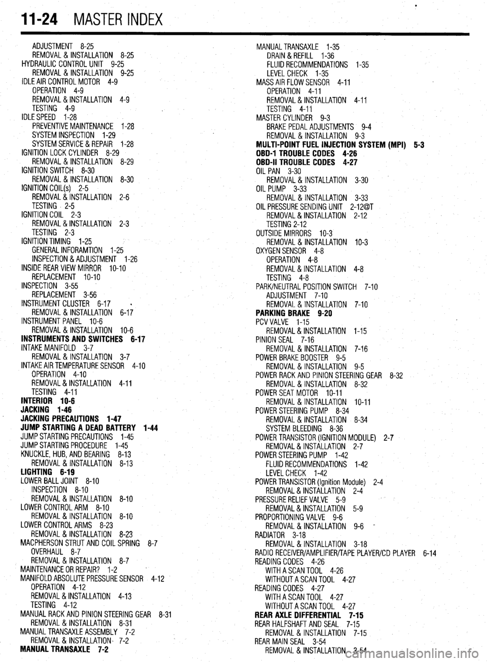
l
II-24 MASTER INDEX
ADJUSTMENT 8-25
REMOVAL &INSTALLATION 8-25
HYDRAULIC CONTROL UNIT 9-25
REMOVAL & INSTALLATION 9-25
IDLE AIR CONTROLMOTOR 4-9
OPERATION 4-9
REMOVAL&INSTALLATION 4-9
TESTING 4-9
IDLESPEED 1-28
PREVENTIVEMAINTENANCE 1-28
SYSTEM INSPECTION 1-29
SYSTEMSERVlCE&REPAlR 1-28
IGNITION LOCK CYLINDER 8-29
REMOVAL & INSTALLATION 8-29
IGNITION SWITCH 8-30
REMOVAL & INSTALLATION 8-30
IGNITION COIL(s) 2-5
REMOVAL&INSTALLATION 2-6
TESTING . 2-5
IGNITION COIL 2-3
REMOVAL&INSTALLATION 2-3
TESTING 2-3
IGNITION TIMING l-25
GENERALINFORAMTION l-25
INSPECTION&ADJUSTMENT l-26
INSIDE REAR VIEW MIRROR
IO-IO
REPLACEMENT IO-IO
INSPECTION 3-55
REPLACEMENT 3-56
INSTRUMENT CLUSTER 6-17
REMOVAL&INSTALLATION 6-I;
INSTRUMENTPANEL IO-6
REMOVAL &INSTALLATION IO-6
INSTRUMENTS AND SWITCHES 6-17
INTAKE MANIFOLD 3-7
REMOVAL &INSTALLATION 3-7
INTAKEAIRTEMPERATURESENSOR 4-10
OPERATION 4-10
REMOVAL&INSTALLATION 4-11
TESTING 4-11
INTERIOR 1 O-6
JACKING I-46
. JACKING PRECAUTIONS 1-47
JUMP STARTING A DEAD BATTERY 1-44
JUMPSTARTING PRECAUTIONS l-45
JUMPSTARTING PROCEDURE l-45
KNUCKLE,HUB, AND BEARING 8-13
REMOVAL &INSTALLATION 8-13
LIGHTING 6-19
LOWER BALLJOINT 8-10
INSPECTION 8-10
REMOVAL & INSTALLATION 8-10
LOWER CONTROLARM 8-10
REMOVAL&INSTALLATION 8-10
LOWER CONTROL ARMS 8-23
REMOVAL & INSTALLATION 8-23
MACPHERSONSTRUTAND COILSPRING
8-7
OVERHAUL 8-7
REMOVAL & INSTALLATION 8-7
MAINTENANCEORREPAIR? l-2
MANIFOLDABSOLUTEPRESSURESENSOR
4-12
OPERATION 4-12
REMOVAL&INSTALLATION 4-13
TESTING 4-12
MANUAL RACK AND PINION STEERING GEAR
8-31
REMOVAL & INSTALLATION 8-31
MANUALTRANSAXLEASSEMBLY 7-2
REMOVAL & INSTALLATION. 7-2
MANUAL TRANSAXLE 7-2 MANUALTRANSAXLE l-35
DRAIN &REFILL l-36
FLUID RECOMMENDATIONS l-35
LEVEL CHECK l-35
MASSAIRFLOWSENSOR 4-11
OPERATION 4-11
REMOVAL&INSTALLATION 4-11
TESTING 4-11
MASTER CYLINDER 9-3
BRAKE PEDALADJUSTMENTS 9-4
REMOVAL & INSTALLATION 9-3
MULTI-POINT FUEL INJECTION SYSTEM (MPI) 5-3
DBD-1 TROUBLE CODES 4-26
OBD-II TROUBLE CODES 4-27
OIL PAN 3-30
REMOVAL & INSTALLATION 3-30
OIL PUMP 3-33
REMOVAL & INSTALLATION 3-33
OIL PRESSURESENDING UNIT 2-12@T
REMOVAL&INSTALLATION 2-1.2
TESTING 2-12
OUTSIDE MIRRORS IO-3
REMOVAL&INSTALLATION IO-3
OXYGENSENSOR 4-8
OPERATION 4-8
REMOVAL&INSTALLATION 4-8
TESTING 4-8
PARK/NEUTRAL POSITIONSWITCH 7-10
ADJUSTMENT 7-10
REMOVAL & INSTALLATION 7-10
PARKING BRAKE 9-20
PCVVALVE l-15
REMOVAL&INSTALLATION I-15
PINION SEAL 7-16
REMOVAL &INSTALLATION 7-16
POWER BRAKEBOOSTER 9-5
REMOVAL &INSTALLATION 9-5
POWER RACK AND PINION STEERING GEAR 8-32
REMOVAL &INSTALLATION 8-32
POWERSEATMOTOR IO-11
REMOVAL & INSTALLATION IO-11
POWER STEERING PUMP 8-34
REMOVAL & INSTALLATION 8-34
SYSTEM BLEEDING 8-36
POWER TRANSlSTOR(IGNITION MODULE) 2-7
REMOVAL&INSTALLATION 2-7
POWERSTEERING PUMP l-42
FLUID RECOMMENDATIONS l-42
LEVELCHECK l-42
POWER TRANSlSTOR(Ignition Module) 2-4
REMOVAL&INSTALLATION 2-4
PRESSURERELIEFVALVE 5-9
REMOVAL&INSTALLATION 5-9
PROPORTIONING VALVE 9-6
REMOVAL & INSTALLATION 9-6 *
RADIATOR 3-18
REMOVAL &INSTALLATION 3-18
RADIO RECEIVER/AMPLIFIER/TAPE PLAYER/CD PLAYER 6-14
READING CODES 4-26
WITHASCANTOOL 4-26
WITHOUTASCANTOOL 4-27
READING CODES 4-27
WITHASCANTOOL 4-27
WITHOUTASCANTOOL 4-27
REAR AXLE DIFFERENTIAL 7-15
REAR HALFSHAFTAND SEAL 7-15
REMOVAL&INSTALLATION 7-15
REAR MAIN SEAL 3-54
REMOVAL & INSTALLATION 3-54
Page 407 of 408
MASTER INDEX 11-25 -
REAROUTPUTSHAFTSEAL 7-14
TESTING 6-5
REMOVAL & INSTALLATION 7-14
' THERMOSTAT 3-7
REAR SUSPENSION 8-18 REMOVAL & INSTALLATION 3-7
REAR WINDOW WIPER SWITCH 6-19 THROTTLE BODY 5-3
REMOVAL&INSTALLATION 6-19 REMOVAL & INSTALLATION 5-3
REARDRlVEAXLE(AWDGALANTONLY) l-38
THROTTLEPOSITIONSENSOR 4-13
DRAIN &REFILL 1-38
OPERATION 4-13
FLUIDRECOMMENDATIONS 1-38 , REMOVAL&INSTALLATION 4-13
LEVELCHECK l-38
TESTING 4-13
REGULATOR 2-10 TIMING COVERAND BELT 3-36
REMOVAL&INSTALLATION 2-10
INSPECTION 3-48
RELIEVING FUELSYSTEM PRESSURE 5-3 REMOVAL & INSTALLATION 3-36
ROCKERARM(VALVE)COVER 3-1
TIMING BELTS l-20
REMOVAL & INSTALLATION 3-1
INSPECTION I-20
ROCKER ARM/SHAFTS 3-4
TIRESANDWHEELS I-30
REMOVAL & INSTALLATION 3-4
CAREOFSPECIALWHEELS l-32
ROUTINE MAINTENANCE AND TUNE-UP 1-14 INFLATION & INSPECTION I-31
SEATS IO-IO
TIRE DESIGN I-31
REMOVAL&INSTALLATION IO-IO TIRE ROTATION I-30
SENDING UNITS 2-11
TIRESTORAGE I-31
SERIAL NUMBER IDENTIFICATION l-10
TONE (EXCITER) RING 9-29
SERVICING YOUR VEHICLE SAFELY I-4
REMOVAL & INSTALLATION 9-29
SHOCKABSORBERAND COILSPRING 8-8
TOOLS AND EQUIPMENT 1-2
OVERHAUL 8-9
TORQUE 1-7
REMOVAL&INSTALLATION 8-8 TORQUEANGLEMETERS l-9
SIGNAL AND MARKER LIGHTS 6-21
TORQUEWRENCHES l-7
REMOVAL & INSTALLATION 6-21
TOWING THE VEHICLE 1-44
SPARKPLUG WIRES 1-24
TRAINING ARM 8-24
REMOVAL&INSTALLATION 1-24
REMOVAL & INSTALLATION 8-24
TESTING 1-24
TRANSAXLEIDENTIFICATION I-10
SPARKPLUGS l-22
TRANSFER CASE ASSEMBLY 7-14
INSPECTION &GAPPING l-23
REMOVAL & INSTALLATION 7-14
REMOVAL&INSTALLATION 1-22
TRANSFER CASE 7-14
SPARKPLUGHEATRANGE 1-22
TRANSFERCASE(AWD GALANT ONLY) 1-38
SPEAKERS 6-14
DRAIN &REFILL 1-38
REMOVAL & INSTALLATION 6-14
FLUIDRECOMMENDATIONS 1-38
SPECIALTOOLS 1-4
LEVELCHECK 1-38
SPEED SENSORS 9-28
TRANSFERCASE(AWDGALANTONLY) I-10
REMOVAL & INSTALLATION 9-28
TROUBLESHOOTING ELECTRICALSYSTEMS 6-5
STANDARDANDMETRIC MEASUREMENTS l-9
OPEN CIRCUITS 6-5
STARTER 2-10
RESISTANCE 6-8
REMOVAL&INSTALLATION 2-11
SHORT CIRCUITS 6-6
TESTING 2-10
VOLTAGEDROP 6-6
STARTING SYSTEM 2-10
VOLTAGE 6-6
STEERING LINKAGE 8-30
TRUNK LID IO-3
REMOVAL &INSTALLATION 8-30
ALIGNMENT IO-3
STEERING WHEEL 8-27
REMOVAL & INSTALLATION IO-3
REMOVAL &INSTALLATION 8-27
TURBOCHARGER 3-17
STEERING 8-27
REMOVAL & INSTALLATION 3-17
STRUT AND COIL SPRING
8-21
UNDERSTANDING AND TROUBLESHOOTING ELECTRICAL
OVERHAUL 8-22
SYSTEMS 6-2
REMOVAL & INSTALLATION 8-21
UNDERSTANDINGTHEAUTOMATICTRANSAXLE 7-10
STUBAXLESHAFT,BEARlNG AND SEAL 7-15
REMOVAL & INSTALLATION 7-10
REMOVAL&INSTALLATION 7-15
UNDERSTANDINGTHECLUTCH 7-7
SWAY BAR 8-12
ADJUSTMENTS 7-8
REMOVAL 8, INSTALLATION 8-12
REMOVAL&INSTALLATION 7-7
SWAY BAR 8-25
UNDERSTANDINGTHE MANUALTRANSAXLE 7-2
REMOVAL&INSTALLATION 8-25
SHIFT LINKAGE 7-2
TAILGATE/HATCH HANDLE lo-19
UPPER BALLJOINT 8-9
REMOVAL &INSTALLATION lo-10
INSPECTION 8-9
TAILGATE IO-3
REMOVAL &INSTALLATION 8-9
ALIGNMENT IO-3 i'
UPPER CONTROLARM 8-10
REMOVAL & INSTALLATION IO-3
REMOVAL & INSTALLATION 8-10
TANKASSEMBLY 5-10
UPPER CONTROL ARMS 8-22
REMOVAL&INSTALLATION 5-10
REMOVAL & INSTALLATION 8-22
TEST EQUIPMENT 6-4
VACUUM DIAGRAMS 4-36
JUMPER WIRES 6-4
VALVE LASH 1-27
MULTIMETERS 6-5
ADJUSTMENT 1-27
TEST LIGHTS 6-4
VEHICLE IDENTIFICATION NUMBER I-10