horn MITSUBISHI DIAMANTE 1900 Repair Manual
[x] Cancel search | Manufacturer: MITSUBISHI, Model Year: 1900, Model line: DIAMANTE, Model: MITSUBISHI DIAMANTE 1900Pages: 408, PDF Size: 71.03 MB
Page 222 of 408
CHASSIS ELECTRICAL 6-19
1. Disconnect the negative battery cable.
are all built into 1 multi-function combination
2. Remove the instrument cluster, as outlined 1. Disconnect the negative battery cable.
earlier in this section. switch that is mounted on the steering col-
2. Using a small screwdriver or other suitable
umn. Refer to Section 8 for procedures re-
3. Remove the retaining screws for the instrument tool, carefully pry the retaining clips from either side
garding the combination switch.
cluster lens and cover assembly. Remove the cover of the switch trim plate.
3.
and lens. Carefully pull the switch and trim plate out of
,
4. Remove the retaining screws for the gauge or the instrument panel.
4. Detach the electrical connectors and remove
warning lamp to be replaced, then remove the gauge
the switch.
or warning lamp.
REMOVAL&INSTALLATION : 5. The installation is the reverse of removal.
To install:
5. Place the gauge or warning lamp into place
and tighten the retaining screws. 1. Disconnect the negative battery cable.
6. Install the instrument cluster lens and cover 2. Using a suitable prytool, disengage the switch
assembly. retaining tabs.
REMOVAL &INSTALLATION 7. Install the instrument cluster. 3. Gently pull the switch from the instrument
8. Connect the negative battery cable. panel.
4. Detach the electrical connector and remove the *On all models the headlights, turn signals,
switch. and on some models, the cruise control func-
5. The installation is the reverse of removal. tion are all built into 1 multi-function combi-
nation switch that is mounted on the steerinq
REMOVAL &INSTALLATION column. Refer to Section 8 for procedures 6
garding the combination switch.
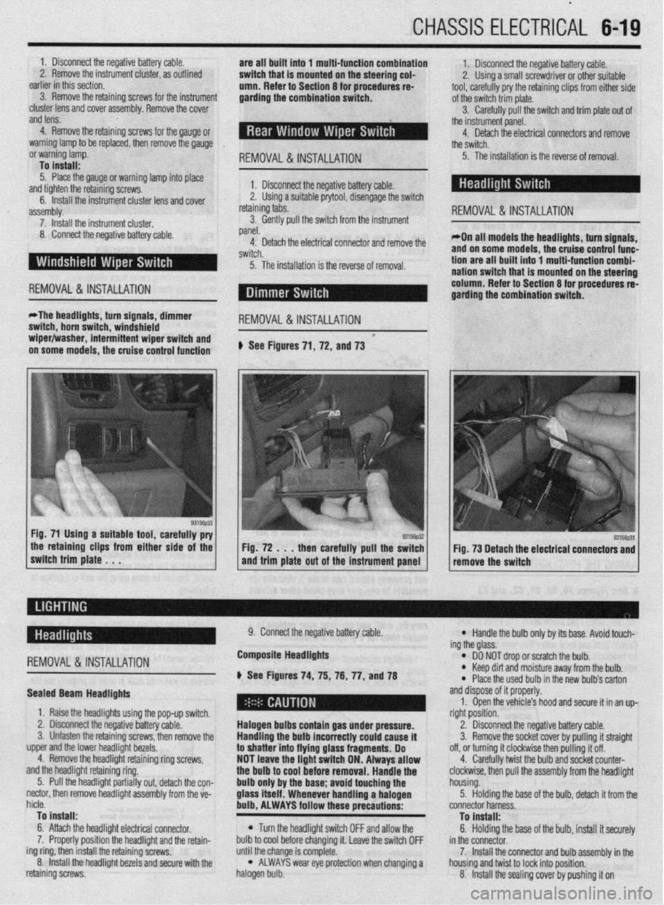
*The headlights, turn signals, dimmer
switch, horn switch, windshield
REMOVAL &INSTALLATION
wiper/washer, intermittent wiper switch and *
on some models, the cruise control function # See Figures 71, 72, and 73
the retaining clips from either side of the
switch trim plate . . . Fig. 72 . . . then carefully pull the switch
and trim plate out of the instrument panel Fig. 73 Detach the electrical connectors and
remove the switch
-
REMOVAL &INSTALLATION
Sealed Beam Headlights
1. Raise the headlights using the pop-up switch.
2. Disconnect the negative battery cable.
3. Unfasten the retaining screws, then remove the
upper and the lower headlight bezels.
4. Remove the headlight retaining ring screws,
and the headlight retaining ring.
5. Pull the headlight partially out, detach the con-
nectar, then remove headlight assembly from the ve-
hicle.
To install:
6. Attach the headlight electrical connector.
7. Properly position the headlight and the retain-
ing ring, then install the retaining screws.
8. Install the headlight bezels and secure with the
retaining screws. 9. Connect the negative battery cable.
Composite Headlights
6 See Figures 74, 75, 76, 77, anU78
Halogen bulbs contain gas under pressure.
Handling the
bulb incorrectly could cause it
to shatter into flying glass fragments. Do
NOT leave the light switch ON. Always allow
the bulb to cool before removal. Handle the
bulb only by the base; avoid touching the
glass itself. Whenever handling a halogen
bulb, ALWAYS follow these precautions:
l Turn the headlight switch OFF and allow the
bulb to cool before changing it. Leave the switch OFF
until the change is complete.
l ALWAYS wear eye protection when changing a
halogen bulb.
l Handle the bulb only by its base. Avoid touch-
ing the glass.
l DO NOT drop or scratch the bulb. l Keep dirt and moisture away from the bulb.
* Place the used bulb in the new bulb’s carton
and dispose of it properly.
1. Open the vehicle’s hood and secure it in an up-
right position.
2. Disconnect the negative battery cable.
3. Remove the socket cover by pulling it straight
off, or turning it clockwise then pulling it off.
4. Carefully twist the bulb and socket counter-
clockwise, then pull the assembly from the headlight
housing.
5. Holding the base of the bulb, detach it from the
connector harness.
To install:
6. Holding the base of the bulb, install it securely
in the connector.
7. Install the connector and bulb assembly in the
housing and twist to lock into position.
8. Install the sealing cover by pushing it on
Page 232 of 408
CHASSIS ELECTRlCiL 6-29
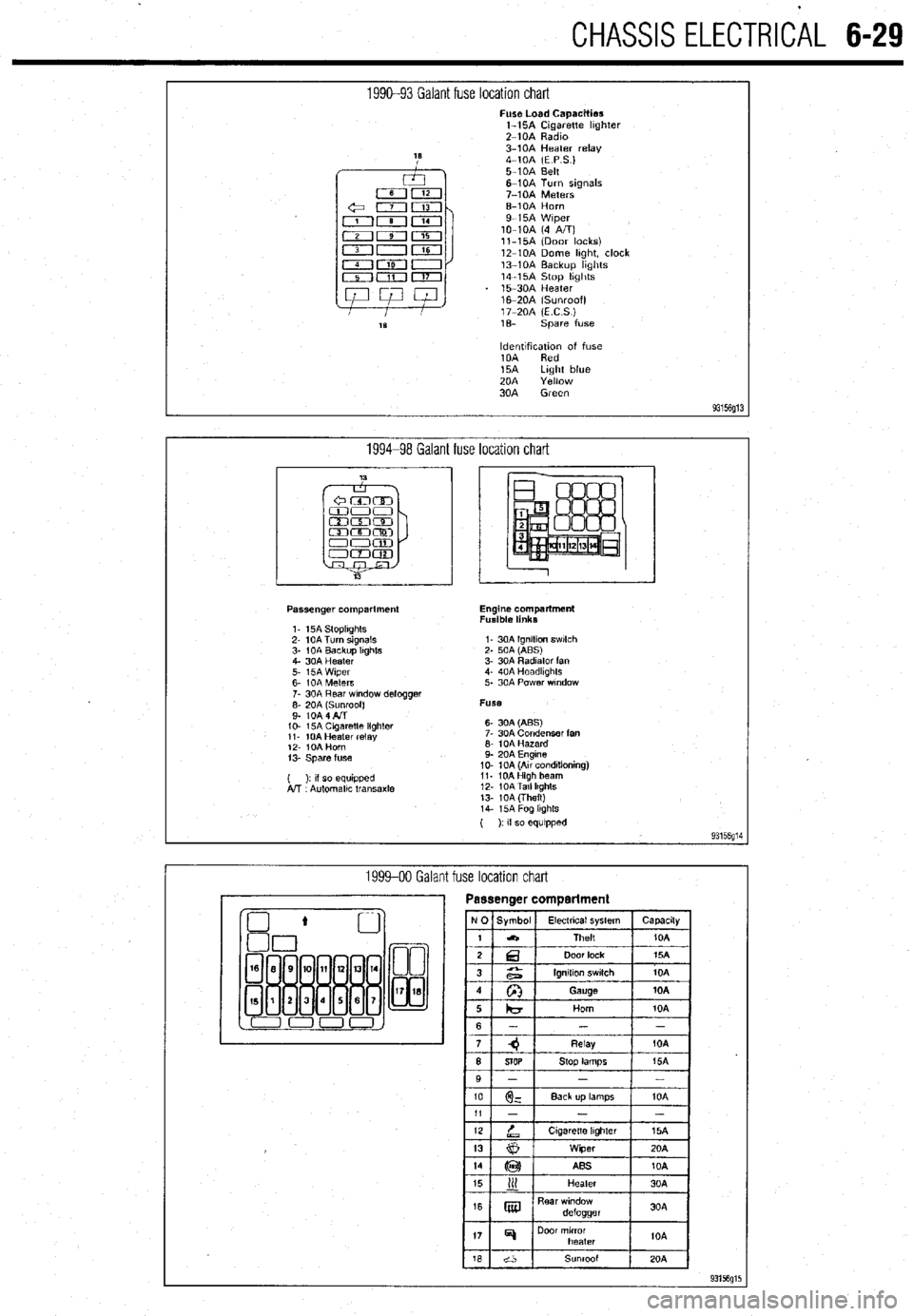
1990-93 Galant fuse location chart Fuse Load Capacities
l-15A Cigarette hghter
Z-10A Radm
3-10A Heater relay
4-10A (E P S.)
5-10A Belt
6-10A Turn signals
7-10A Meters
6-10A Horn
9-15A Wiper
lo-10A (4 A/T)
ll-15A (Door locks)
12-10A Dome hght, clock
13-10A Backup hghts
14-15A Stop hghts
15-30A Heater
16m20A (Sunroof)
17-20A (ECS)
1% spare fuse
ldentlfxation of fuse
10A Red
15A Light blue
20A Yellow
30A Green
93156g13
1994-98 Galant fuse location chart
Passenger compartment
1. 15A StoplIghts
2- 10A Turn signals
3- 1 OA Backup Itghts
4. 30A Heater
5. i5A Wiper
6- IOA Meters
7. 30A Rear wndow defogger
;: fo& fl$oof)
IO- 15A Cagaretle lighler
11. 10A Heater relay
12. IOA Horn
13. Spare fuse
( ): II so equipped
A!T Automallc transaxle Engine compartment
Fusible links
I- 30A Ignition swlch
2. 50A (ABS)
3. 30A Radiator fan
4. 40A Headkghts
5. 30A Power wndow
Fuse
6- 30A (ABS)
7. 30A Condenser fan
6. 10A Hazard
9. 20A Engine
10. 10A (Au conditioning)
11. 10AHigh beam
12. 10ATall lkghts
13. 10A (Theft)
14. i5A Fog lkghls
( ): If so equipped
93156g14
1999-00 Galant fuse location chart
Page 233 of 408
6-30 CHASSIS ELECTRICAL
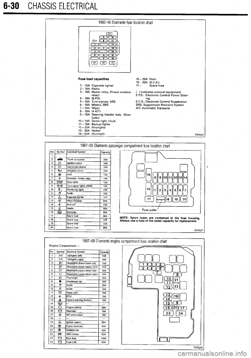
1992-96 Diamante fuse location chart
I
Fuse load caaacities 15 -2OA Horn
16 - 20A (E.C.S.)
1 - 15A Cigarette lighter 17 - spare fuse
2 - 10A Radio
3 - 10A Heater relay, (Power window ( ) indicates optlonal equipment
relay) E P.S.: Electronic Control Power Steer-
4 - 10A (E.P.S) ing
5 - 10A Turn signals, SRS E.C.S.: Electronic Control Suspension
6 - 10A Meters, SRS SRS~ Supplement Restratnt System
7 - 15A Wiper A/T: Automatic Transaxle
8-10A (4AIT)
9- 15A Steering handle lock, (Door
locks)
lo- 10A Dome light, Clock
11 - 10A Backup lights
12 -2OA StoplIghts
13 -3OA Heater
14 - 20A (Sunroof)
93156fllE
1997-00 Diamante passenger compartment fuse location chart No Symbol Electrical System
I capactty
I
Spare fuses are contained in the fuse housing
use a fuse of the same capacity for replacement.
199740 Diamante encline
compartment fuse location chart
Page 234 of 408
CHASSIS ELECTRICAL 6-31
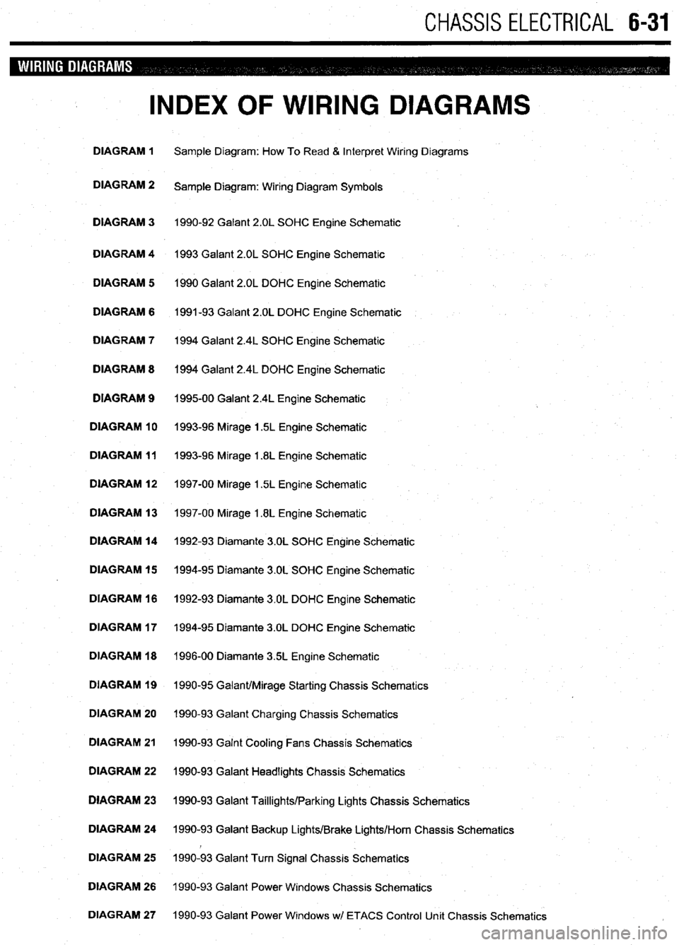
INDEX OF WIRING DIAGRAMS
DIAGRAM 1 Sample Diagram: How To Read & Interpret Wiring Diagrams
DIAGRAM 2
Sample Diagram: Wiring Diagram Symbols
DIAGRAM 3 1990-92 Galant 2.OL SOHC Engine Schematic
DIAGRAM 4 1993 Galant 2.OL SOHC Engine Schematic
DIAGRAM 5 1990 Galant 2.OL DOHC Engine Schematic
DIAGRAM 6 1991-93 Galant 2.OL DOHC Engine Schematic
DIAGRAM 7 1994 Galant 2.4L SOHC Engine Schematic
DIAGRAM 8 1994 Galant 2.4L DOHC Engine Schematic
DIAGRAM 9
199500 Galant 2.4L Engine Schematic
DIAGRAM 10 1993-96 Mirage 1.5L Engine Schematic
DIAGRAM 11 1993-96 Mirage 1.8L Engine Schematic
DIAGRAM 12 1997-00 Mirage 1.5L Engine Schematic
DIAGRAM 13 1997-00 Mirage 1.8L Engine Schematic
DIAGRAM 14 1992-93 Diamante 3.OL SOHC Engine Schematic
DIAGRAM 15 1994-95 Diamante 3.OL SOHC Engine Schematic
DIAGRAM 16 1992-93 Diamante 3.OL DOHC Engine Schematic
DIAGRAM 17 1994-95 Diamante 3.OL DOHC Engine Schematic
DIAGRAM 18 1996-00 Diamante 35L Engine Schematic
DIAGRAM 19 1990-95 Galant/Mirage Starting Chassis Schematics
DIAGRAM 20 1990-93 Galant Charging Chassis Schematics
DIAGRAM 21 1990-93 Galnt Cooling Fans Chassis Schematics
DIAGRAM 22 1990-93 Galant Headlights Chassis Schematics
DIAGRAM 23 1990-93 Galant Taillights/Parking Lights Chassis Schematics
DIAGRAM 24 1990-93 Galant Backup Lights/Brake Lights/Horn Chassis Schematics
DIAGRAM 25 1990-93 Galant Turn Signal Chassis Schematics
DIAGRAM 26 1990-93 Galant Power Windows Chassis Schematics
DIAGRAM 27 1990-93 Galant Power Windows wl ETACS Control Unit Chassis Schematics
Page 235 of 408

6-32 CHASSIS ELECTRICAL
INDEX OF WIRING DIAGRAMS
DIAGRAM 28 1990-93 Galant Wipers Chassis Schematics
DIAGRAM 29 1990-93 Galant Wipers w/ ETACS Control Unit Chassis Schematics
DIAGRAM 30 1990-93 Galant Power Door Locks Chassis Schematics
DIAGRAM 31 1990-93 Galant Power Door Locks wl ETACS Control Unit Chassis Schematics
DIAGRAM 32 1996-00 Galant Starting System Chassis Schematics
DIAGRAM 33 1994-00 Galant Charging System Chassis Schematics
DIAGRAM 34 1994-00 Galant Charging System Chassis Schematics
DIAGRAM 35 1994-00 Galant Headlights Chassis Schematics
DIAGRAM 36 1994-00 Galant Taillights Chassis Schematics
DIAGRAM 37 1994-00 Galant Brake Lights/Backup Lights/Horn Chassis Schematics
DIAGRAM 38 1994-00 Galant Turn Signal Chassis Schematics
DIAGRAM 39 1994-00 Galant Power Windows Chassis Schematics
m
DIAGRAM 40 1994-00 Galant Wipers Chassis Schematics
b
DIAGRAM 41 1994 Galant Power Door Locks w/ ETACS Control Unit Chassis Schematics
DIAGRAM 42 1994-00 Galant Power Door Locks Chassis Schematics
DIAGRAM 43 1992-00 Diamante Starting System Chassis Schematics
DIAGRAM 44 1992-00 Diamante Charging System Chassis Schematic
DIAGRAM 45 1992-93 Diamante Cabling System Chassis Schematic
DIAGRAM 46 1994-95 Diamante Cooling System Chassis Schematics
DIAGRAM 47 1996-00 Diamante Headlights Chassis Schematics
DIAGRAM 48 1992-95 Diamante Taillights/Backup Lights Chassis Schematics
DIAGRAM 49 1992-95 Diamante Turn Signal Chassis Schematics
DIAGRAM 50 1992-00 Diamante Brake Lights, Horn Chassis Schematic
DIAGRAM 51 1992-95 Diamante Power Windows Chassis Schematics
DIAGRAM 52 1992-95 Diamante Wipers Chassis Schematics
DIAGRAM 53 1992-93 Diamante Power Door Locks Chassis Schematics
Page 236 of 408
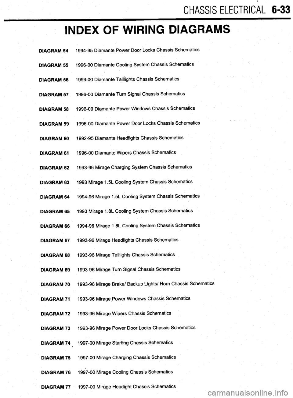
CHASSIS ELECTRlCiL 6-33
INDEX OF WIRING DIAGRAMS
DIAGRAM 54
DIAGRAM 55
DIAGRAM 56
DIAGRAM 57
DIAGRAM 58
DIAGRAM 59
DIAGRAM 60
DIAGRAM 61
DIAGRAM 62
DIAGRAM 63
DIAGRAM 64
DIAGRAM 65
DIAGRAM 66
DIAGRAM 67
DIAGRAM 68
DIAGRAM 69
DIAGRAM 70
DIAGRAM 71
DIAGRAM 72
DIAGRAM 73
DIAGRAM 74
DIAGRAM 75
DIAGRAM 76
DIAGRAM 77 1994-95 Diamante Power Door Locks Chassis Schematics
1996-00 Diamante Cooling System Chassis Schematics
1996-00 Diamante Taillights Chassis Schematics
1996-00 Diamante Turn Signal Chassis Schematics
1996-00 Diamante Power Windows Chassis Schematics
1996-00 Diamante Power Door Locks Chassis Schematics
1992-95 Diamante Headlights Chassis Schematics
1996-00 Diamante Wipers Chassis Schematics
1993-96 Mirage Charging System Chassis Schematics
1993 Mirage 1.5L Cooling System Chassis Schematics
1994-96 Mirage 1.5L Cooling System Chassis Schematics
1993 Mirage 1.8L Cooling System Chassis Schematics
1994-96 Mirage 1.8L Cooling System Chassis Schematics
1993-96 Mirage Headlights Chassis Schematics
1993-96 Mirage Taillights Chassis Schematics
1993-96 Mirage Turn Signal Chassis Schematics
1993-96 Mirage Brake/ Backup Lights/ Horn Chassis Schematics
1993-98 Mirage-Power Windows Chassis Schematics
1993-96 Mirage Wipers Chassis Schematics
1993-96 Mirage Power Door Locks Chassis Schematics
1997-00 Mirage Starting Chassis Schematics
1997-00 Mirage Charging Chassis Schematics
1997-00 Mirage Cooling Chassis Schematics
1997-00 Mirage Headight Chassis Schematics
Page 237 of 408
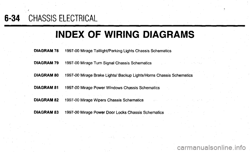
6-34 CHASSIS ELECTRICAL
INDEX OF WIRING DIAGRAMS
DIAGRAM 78 1997-00 Mirage Taillight/Parking Lights Chassis Schematics
DIAGRAM 79
1997-00 Mirage Turn Signal Chassis Schematics
DIAGRAM 80 1997-00 Mirage Brake Lights/ Backup Lights/Horns Chassis Schematics
DIAGRAM 81
1997-00 Mirage Power Windows Chassis Schematics
DIAGRAM 82 1997-00 Mirage Wipers Chassis Schematics
DIAGRAM 83 1997-00 Mirage Power Door Locks Chassis Schematics
Page 262 of 408

1992-95 DIAMANTE CHASSIS SCHEMATIC
1992-00 DIAMANTE CHASSIS SCHEMATIC
F
0 0
7
TURN SIGNAL *ND
HAZARO FLASHER
UNIT
LEFT
REAR
COMBINATIQI
LIGHT LEFT
REM
LID
LIGHT
1992-95 HOT AT ALL TIMES
> FUSE
I6
”
E&l
*
1 HIGN
MOUMED
CI
STOP
LIGHT
? RIGHT
REM
LID
LIGHT
m ” RIGHT
REAR
cotlBINATta
LIGHT
2 3
ZEY
-------
t
e ”
(L
TO
ETACS
L!NlT
HORN
SWITCH
1996-00 HOT AT ALL TIMES
FUSE
19
ISA
1 HORN RELAY
DIAGRAM 49
DIAGRAM 50 93156635 93156B36
Page 324 of 408
. . . ,.x ..-~ .-....,, _s_s”., .._ ” *
8-28 SUSPENSION AND STEERING
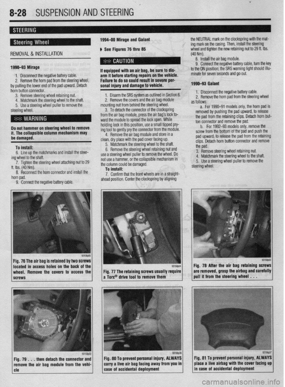
REMOVAL&INSTALLATION
199%93 Mirage 1994-00 Mirage and Galant
b See Figures 76 thru 85 the NEUTRAL mark on the clockspring with the mat-
f ing mark on the casing. Then, install the steering
wheel and tighten the new retaining nut to 29 ft. Ibs.
(40 Nm).
8. Install the air bag module.
1. Disconnect the negative battery cable.
2. Remove the horn pad from the steering wheel,
by pulling the lower end of the pad upward. Detach I
If aqui
arm it --.-.- ---.-...= .-r-.‘- -.. _..- ._.. - -
Failure to do so could result in severe per-
sonal injury and damage to vehicle. pped with an air bag, be sure to dls- hnfnra sfarfinn rmairs on the vehicle.
9. Connect the negative battery cable, turn the key
to the ON position; the SRS warning light should illu-
minate for seven seconds and go out.
1990-93 Galant
hbin butin connector.
3. Remove steering wheel retaining nut:
. . . .‘ .
a. .a I <.
4. Matcnmarlc me steering wneel to me snan.
5. Use a steering wheel puller to remove the
steering wheel.
Do not hammer on steering wheel to remove
it. The collapsible column mechanism may
ha rlsmwmd.
To install:
6. Line up the matchmarks and install the steer-
ing wheel to the shaft.
7. Ti flhten the steering wheel attaching nut to 29
ft. Ibs. (40 Nm).
8. Reconnect the horn connector and install the
horn pad.
9. Connect the neaative battetv cable. 1. Disarm the SRS system as outlined in Section 6.
^ m *I
sand the air bag module
.,A +L. m++-,g w,,eel,
*. I z. Remove me cover
mounting nut from behill” ~IK ~(G~G!I
3. To detach the connector of the clocKsprmfl
from the air bag module, press the air bag’s lock to-
ward the module to spread the lock open. While
holding lock in this position, use a small tipped pry-
ing tool to gently pry the connector from the module.
4. Remove the air bag module and store in a
clean, dry place with the pad cover facing up.
5. Matchmark the steering wheel to the shaft.
6. Remove the steering wheel retaining nut and
use a steering wheel puller to remove the wheel. Do
not use a hammer, or the collapsible mechanism in
the column could be damaged.
To install:
7. Confirm that the front wheels are in a straight-
ahead position. Center the clocksprinfl by aligning 1. Disconnect the negative battery cable.
2. Remove the horn oad from the steerino wheel
as follows:- - - - r d
a. For 1990-91 models only, the horn pad is
removed by pushing the pad upward, to release
the pad from the retaining clips. Detach horn but-
ton connector and remove the pad.
b.
For 1992-93 models only, remove the
screw from the bottom of the pad and push the
pad upward, to release the pad from the retaining
clips. Detach horn button connector and remove
the pad.
3. Remove steering wheel retaining nut.
4. Matchmark the steering wheel to the shaft.
5. Use a steering wheel puller to remove the
steering wheel.
Fig. 76 The air bag is retained by two 8
located in access holes on the back
wheel. Remove the covers to access the
screws Fig. 78 After the air baa
retainino screws
Fig. 77 The retaining screws usually require are removed, grasp the airbag andiarefully
a Torx@ drive tool to remove them pull it from the steering wheel . . .
then detach the connector and Fig. 80 To prevent personal injury, ALWAYS fig. 81 To prevent personal Injury, ALWAYS
ove the air bag module from the vehi- carry a live air bag facing away from you in place a live airbag with the cover facing up
Page 325 of 408
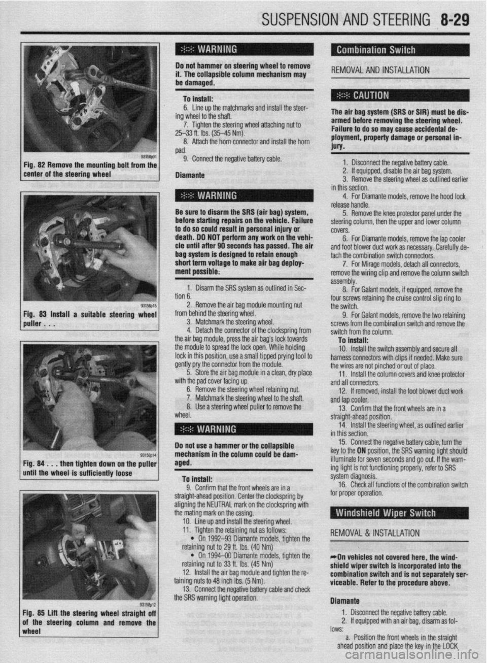
SUSPENSION AND STEERING 8-29
i ’
Do not hamme i4 l-ha nnlhnr !r on steering wheel to remove
,,. , II= ,,,,,,Jfble column mechanism may REMOVALANDINSTALLATION
I
be damaged.
To install:
ing
7.
6. Line up the matchmarks and install the steer-
/heel to the shaft.
Tighten the steering wheel attaching nut to
25-33 ft. Ibs. (35-45 Mm).
8. Attach the horn connector and install the horn
pad.
9. Connect the negative battery cable.
Diamante The air bag system (SRS or SIR) must be dis-
armed before removing the steering wheel.
Failure to do so may cause accidental de-
ployment, property damage or personal in-
MY.
1 Rscnnnnd the nnmtivn hattm rJhle . I._“” . ..I_. . ..I *.-~ _...” ““.‘“‘, _““._. 2. If equipped, disable the air bag system.
3. Remove the steering wheel as outlined earlier
in this section.
Be sure to disarm the SRS (air bag
before starting repairs OI
to do so could result in p
death. DO NOT perform ;
cle until after 90 seconds has passed. The ai
bag system is designed to retain enough
short term voltage to make air bag deploy-
ment possible; I) system,
n the vehicle. Failure
lersonal injury or
any work on the vehi-
ir 4. For Diamante models, remove the hood lock
release handle.
5. Remove the knee protector panel under the
steering column, then the upper and lower column
covers.
6. For Diamante models, remove the lap cooler
and foot blower duct work as necessary. Carefully de-
non
b. 1. Disarm the SRS system as outlined in Sec-
. . ^ I assembly. tach the combination switch connecto&.
8. -
7. For Mirage models, detach all connectors,
For Galant models, if equipped, remove the remove the wiring clip and remove the column switch
2. Remove the air bag module mounting nut
from behind the steering wheel.
3. Matchmark the steering wheel.
4. Detach the connector of the clockspring from
the air baq module, press the air baa’s lock towards four screws retaining the cruise control slip ring to
the switch.
9. For Galant models, remove the two retaining
screws from the combination switch and remove the
switch from the column.
Tn install: the modub to spread the lock open:While holding
lock in this position, use a small tipped prying tool to
gently pry the connector from the module.
5. Store the air bag module in a clean, dry place
..# ,I I I .
ut.
Iaft. wlrn me paa cover racmg up.
6. Remove the steering wheel retaining nl
7. Matchmark the steering wheel to the sl
8. Use a steering wheel puller to remove the
wheel. - . . - _-. . _
10. Install the switch assembly and secure all
harness connectors with clips if needed. Make sure
the wires are not pinched orout of place.
11. Install the column covers and knee protector
and all connectors.
12. If removed, install the foot blower duct work
anfl tan cnnler -..- .-
r --- ”
13. Confirm that the front wheels are in a
straight-ahead position.
14. Install the steering wheel, as outlined earlier
in thir
Do not use a hammer or the ~r”---‘~‘- 15. Connect the negative battery cable, turn the
key to the ON position, the SRS warning light should
NW down
rinntlv
wImpl* the puller
iem Fig. 84 . . . then tighte
until the wheel is suffL,,,,, lVvoV
To install:
0 Pnnfirm that thn frnnt whnalc ,?A in , .I. ““llllllll u,a, ,110 ll”lll I.ll~rJlJ CnIj 111 a
straight-ahead position. Center the clockspring by
aligning the NEUTRAL mark on the clockspring with
the mating mark on the casing.
10. Line up and install the steering wheel. illuminate for seven seconds and go out. If the warn-
ing light is not functioning properly, refer to SRS
s’ .’ ystem cllagnosls.
16. Check all functions of the combination switch
for proper operation.
wheel lows:
a. Position the front wheels in the straight
ahead position and place the key in the LOCK
93158p12 Fig. 85 Lift the steering wheel straight off
of the steering column and remove the 11. Tighten the retaining nut as follows:
REMOVAL &INSTALLATION
l On 1992-93 Diamante models, tighten the
nut to 29 ft. Ibs. (40 Nm) retammg I
l On
retaining I
12. lnstal
taining nuts 1
13. Conn
“... . ..” .‘“J...*.” ‘&.“WSJ Y..“.” . ..rn” VII”“..
the SRS warning light operation. 1994-00 Diamante models, tighten the
iut to 33 ft. Ibs. (45 Nm)
II the air bag module and tighten the r&
:o 48 inch Ibs. (5 Nm).
wt the rwnative hatim rahle ami rhwk
*On vehicles not covered here, the wind-
shield wiper switch is incorporated into the
combination switch and is not separately serl
viceable. Refer to the procedure
above.
Diamante
1. Disconnect the negative battery cable.
2. If equipped with an air bag, disarm as fol-
I” .L