reset MITSUBISHI DIAMANTE 1900 Repair Manual
[x] Cancel search | Manufacturer: MITSUBISHI, Model Year: 1900, Model line: DIAMANTE, Model: MITSUBISHI DIAMANTE 1900Pages: 408, PDF Size: 71.03 MB
Page 29 of 408
.
l-30 GENERAL'INFORMATIONAND MAINTENANCE
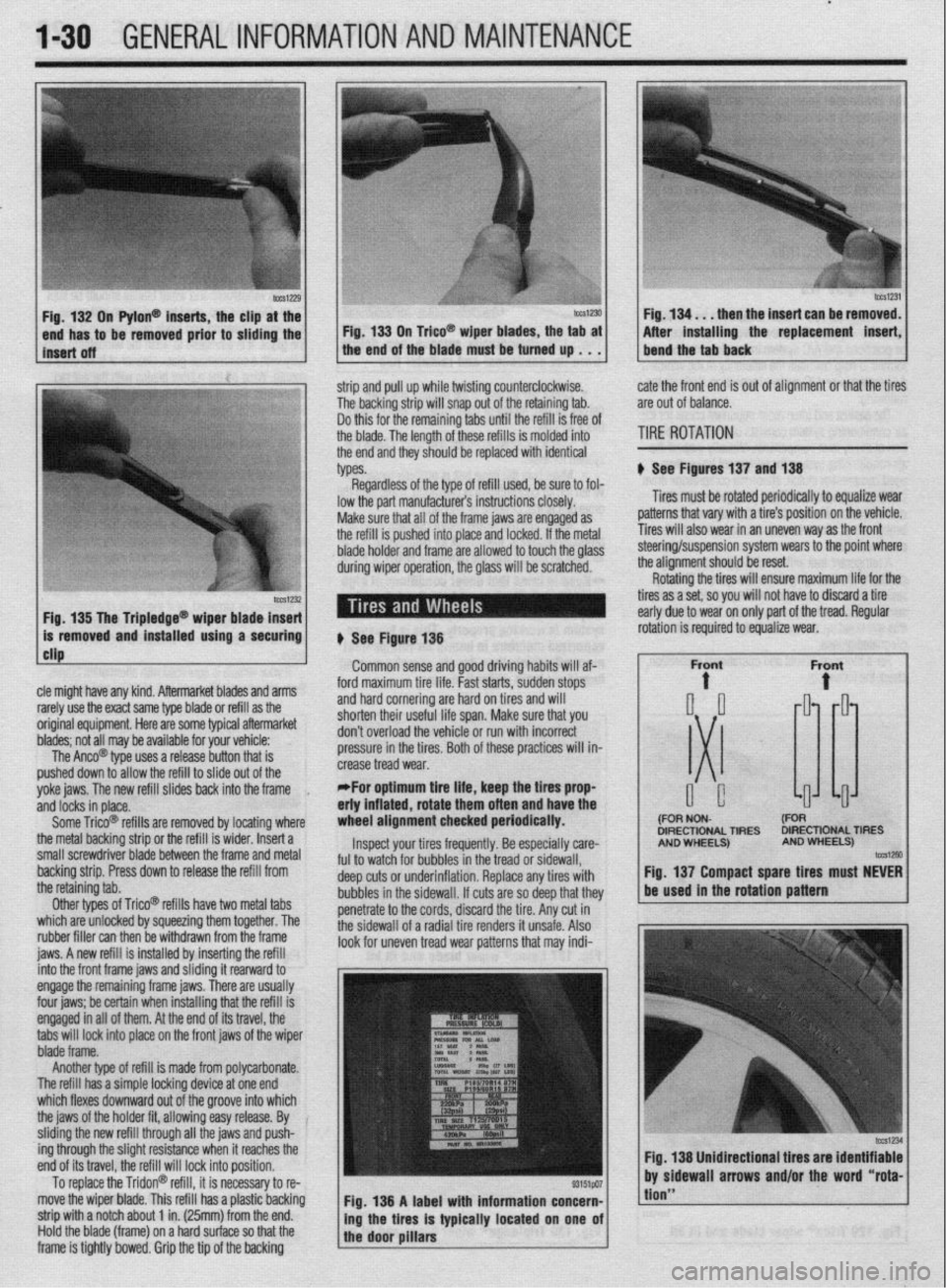
n Pylon@ inserts, the clip
be removed prior to siidi then the insert can be re
After installing the replacement
strip and pull up while twisting counterclockwise.
The backing strip will snap out of the retaining tab.
Do this for the remaining tabs until the refill is free of
the blade. The length of these refills is molded into
the end and they should be replaced with identical
types. cate the front end is out of alignment or that the tires
are out of balance.
TIRE ROTATION
# See Figures 137 and 138
Tires must be rotated periodically to equalize wear
patterns that vary with a tire’s position on the vehicle.
Tires will also wear in an uneven way as the front
1 Fin 1% Tha Trinlarlna@
cle might have any kind. Aftermarket blades and arms
rarely use the exact same type blade or refill as the
original equipment. Here are some typiel aftermarket
blades; not all may be available for your vehicle:
The Anco@ type uses a release button that is
pushed down to allow the refill to slide out of the
yoke jaws. The new refill slides back into the frame
,
and locks in place.
Some Trico@ refills are removed by locating where
the metal backing strip or the refill is wider. Insert a
small screwdriver blade between the frame and metal
backing strip. Press down to release the refill from
the retaining tab.
Other types of Trico@’ refills have two metal tabs
which are unlocked by squeezing them together. The
rubber filler can then be withdrawn from the frame
iaws. A new refill is installed bv insertina the refill lowed to touch the olass steering/suspension system wears to the point where
the alianment should be reset.
# See Figure 138
Common sense and good driving habits will af-
ford maximum tire life. Fast starts, sudden stops
and hard cornering are hard on tires and will
shorten their useful life span. Make sure that you
don’t overload the vehicle or run with incorrect
pressure in the tires. Both of these practices will in-
crease tread wear.
*For optimum tire life, keep the fires prop
eriy inflated, rotate them often and have the
wheel alignment checked periodically.
Inspect your tires frequently. Be especially care-
ful to watch for bubbles in the tread or sidewall,
deep cuts or underinflation. Replace any tires with
bubbles in the sidewall. If cuts are so deep that they
penetrate to the cords, discard the tire. Any cut in
the sidewall of a radial tire renders it unsafe. Also
look for uneven tread wear patterns that may indi- Rotating the tires will ensure maximum life for the
tires as a set, so you will not have to discard a tire
early due to wear on only part of the tread. Regular
DIRECTIONAL TIRES DIRECTIONAL TIRES
jnto the front frame jaws and &ding it rearward to
engage the remaining frame jaws. There are usually
four jaws; be certain when installing that the refill is
engaged in all of them. At the end of its travel, the
tabs will lock into place on the front jaws of the wiper
blade frame.
Another type of refill is made from polycarbonate.
The refill has a simple locking device at one end
which flexes downward out of the groove into which
the jaws of the holder fit, allowing easy release. By
sliding the new refill through all the jaws and push-
ing through the slight resistance when it reaches the
end of its travel, the refill will lock into position.
To replace the Tridon@ refill, it is necessary to re-
move the wiper blade. This refill has a plastic backing
strip with a notch about 1 in. (25mm) from the end.
Hold the blade (frame) on a hard surface so that the
frame is tightly bowed. Grip the tip of the backing Fig. 138 A label with information concern-
ing the tires is typically located on one of
the door pillars
tion”
Page 105 of 408
.
3-44 ENGINEANDENGINEOVERHALJL
31. Connect the negative battery cable.
32. Road test the vehicle.
EXCEPT 1992-94 MODELS
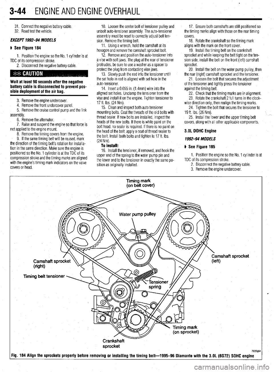
$ See Figure 184
1. Position the engine so the No. 1 cylinder is at
TDC of its compression stroke.
2. Disconnect the negative battery cable.
Wait at least 90 seconds after the negative
battery cable is disconnected to prevent pos-
sible deployment of the air bag.
3. Remove the engine undercover.
4. Remove the front undercover panel.
5. Remove the cruise control pump and the link
assembly.
6. Remove the alternator.
7. Raise and suspend the engine so that force is
not applied to the engme mount,
8. Remove the timing covers from the engine.
9. If the same timing belt will be reused, mark
the direction of the timing belt’s rotation for installa-
tion in the same direction. Make sure the engine is
positroned so the No. 1 cylinder is at the TDC of its
compression stroke and the timing marks are aligned
with the engine’s timing mark indicators on the valve
covers or head. 10. Loosen the center bolt of tensioner pulley and
unbolt auto-tensioner assembly The auto-tensioner
assembly must be reset to correctly adjust belt ten-
sion. Remove the timing belt.
11. Using a wrench, hold the camshaft at its
hexagon and remove the camshaft sprocket bolt.
12. Remove and position the auto-tensioner into
a vise with soft jaws. The plug at the rear of tensioner
protrudes, be sure to use a washer as a spacer to
protect the plug from contacting vise jaws.
13. Slowly push the rod Into the tensioner until
the set hole rn rod is aligned with set hole in the
auto-tensioner.
14. Insert a 0.055 in. (1.4mm) wire into the
aligned set holes. Unclamp the tensioner from the
vise and install it on the engine. Trghten tensroner to
17 ft. Ibs. (24 Nm).
15. Clean and inspect both auto tensioner
mounting bolts. Coat the threads of the old bolts with
thread sealer. If new bolts are installed, Inspect the
heads of the new bolts. If there is white paint on the
bolt head, no sealer is required. If there is no parnt on
the head of the bolt, apply a coat of thread sealer to
the bolt. Install both bolts and tighten to 17 ft. Ibs.
(24 Nm).
To install: 16. Install the tensioner, if removed, and hook the
upper end of the spring to the water pump pin and
the lower end to the tensioner in exactly the same po-
sition as originally installed. 17. Ensure both camshafts are still positioned so
the timing marks align with those on the rear timing
covers.
18. Rotate the crankshaft so the timing mark
aligns with the mark on the front cover.
19. Install the timing belt on the crankshaft
sprocket and while keeping the belt tight on the ten-
sion side, mstall the belt on the front (left) camshaft
sprocket.
20 Install the belt on the water pump pulley, then
the rear (right) camshaft sprocket and the tensioner.
21. Loosen the bolt that secures the adjustment
of the tensioner and lightly press the tensioner
against the timing belt.
22. Check that the timing marks are in alignment.
23 Rotate the crankshaft 2 full turns in the clock-
wise direction only, then realign the timing marks,
24. Tighten the bolt that secures the tensioner to
19 ft. Ibs. (26 Nm).
25. install the lower and the upper timing belt
covers, along with all other applicable components.
3.OL DDHC Engine
1992-94 MODELS
# See Figure 185
1. Position the engine so the No. 1 cylinder is at
TDC of its compression stroke.
2. Disconnect the negative battery cable.
3. Remove the engine undercover.
Timing mark
(on belt cover)
Timing belt tensioner
Crankshaft
sprocket
7923W :ig. 184 Align the sprockets properly before removing or installing the timing belt-1995-96 Diamante with the 3.OL (6672) SDHC engine
Page 171 of 408
4-28 DRIVEABILITYAND EMISSIONS CONTROLS
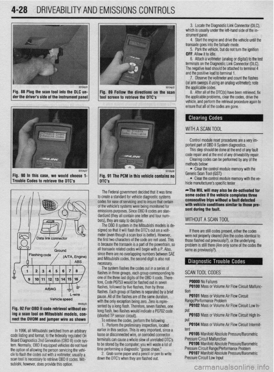
Fig. 88 Plug the scan tool into the DLC un-
Fig. 89 Follow the directions on the scan
der the driver’s side of the instrument panel
tool screen to retrieve the DTC’s 3. Locate the Diagnostic Link Connector (DLC),
which is usually under the left-hand side of the in-
strument panel.
4. Start the engine and drive the vehicle until the
transaxle goes into the failsafe mode.
5. Park the vehicle, but do not turn the ignition
OFF. Allow it to idle.
6. Attach a voltmeter (analog or digital) to the test
terminals on the Diagnostic Link Connector (DLC).
The negative lead should be attached to terminal 4
and the positive lead to terminal 1.
7. Observe the voltmeter and count the flashes
(or arm sweeps if using an analog voltmeter); note
the applicable codes.
- 8. After all of the DTC(s) have been retrieved, fix
the applicable problems, clear the codes, drive the
vehicle, and perform the retrieval procedure again to
ensure that all of the codes are gone.
WITHASCANTOOL
Control module reset procedures are a very im-
portant part of OBD II System diaqnostics.
This step should be done at the end of any fault
code repair and at the end of any driveability repair.
Clearing codes can be performed by any of the
Fig. 90 in this case, we would choor- A ’ ma*-. . . * .
Trouble Codes to retrieve the DTC’s
-.- -
A mere mar
. . methods below: l Clear the control module memory with the
se l-
I I ng. vi me rtim In mts venicie contains no Generic Scan Tool (GST) l DTC’S Clear the control module memory with the ve-
L’-‘m iufacturer’s specific tester
The Federal government decided that it was time
to create a standard for vehicle diagnostic systems
codes for ease of servicing and to insure that certain
of the vehicle’s systems were being monitored for
emissions purposes. Since OBD II codes are stan-
dardized (they all contain one letter and four num-
bers), they are easy to decipher.
The OBD II system in the Mitsubishi models is de-
signed so that it will flash the DTC’s out on a volt-
meter (even though a scan tool is better). However,
the first two characters of the code are not used. This
is because the transaxle is a part of the powertrain, so
all transaxle related codes will begin with a P. Also, *The MIL will may also be de-activated for
some codes if the vehicle completes three
consecutive trips without a fault detected
with vehicle conditions similar to those pre-
sent during the fault.
WITHOUTASCAN TOOL
If there are still codes p
resent, either the codes
were not properly cleared f
:Are the codes identical to
those flashed out previous
I$‘), or the underlying
problem is still there (Are I
only some of the codes the
same as oreviouslv?).
since there are no overlapping numbers between SAE
and Mitsubishi codes, the second digit is also not
necessary.
The system flashes the codes o
ut ma series of
flashes in
three nmm mh nrnlll -- J.-lr-, ---.. ~.--
p corresponding to
one of the
three last diaits of the OBD II code. There-
fore, Code WJJ wuuw UC:
IIKWAJ WI III XVWI flashes, followed by five flashes, then by three
flashes. Each group of flashes is se
pause. All of the flashes are of the (
witi the or$, nvrontinn hoinn mm sented by z
long flash,
(shorted Tt SWIWI LIIW. rparated by a brief
;ame duration,
88, “rw”I.‘L’“‘I uv,,,y LUI”.
Zero is repre-
1 long flash. Therefore, seven flashes, one
two flashes would indicate a PO702 code
3 nnmn^r ,.:*....:I I r
SCANTOOLCODES
. YYY” I ‘I” I cuI”I”.J PO100 Mass or Volume Air Flow Circuit Malfunc-
Lb
non
PO101 Mass orVolume Air Flow Circuit
Range/Performance Problem
PO102 Mass or Volume Air Flow Circuit Low In-
Put
.
To retrieve the codes, perform the following: PO103 Mass or Volume Air Flow Circuit High In-
i Put
1. Perform the preliminary inspection, located PO104 Mass or Volume Air Flow Circuit Intermit-
-;
Vehicle speed es446e35 Fig. 92 For OBO ii code retrieval without us-
ing a scan tool on Mitsubishi models, con-
nect the DVOM and jumper wire as shown
In 1996, all Mitsubishi switched from an arbitrary
code listing and format, to the federally regulated On
Board Diagnostics 2nd Generation (OBD II) code sys-
tern. Normally, OBD II equipped vehicles do not have
the option of allowing the person servicing the vehi-
cle to flash the codes out with a voltmeter; usually a
scan tool is necessary to retrieve OBD II codes. Mit-
subishi, however, does provide this option, earlier in this section. This is very important, since a
loose or disconnected wire, or corroded connector
terminals can cause a whole slew of unrelated DTC’s
to be stored by the computer; you will waste a lot of
time performing a diagnostic “goose chase.”
2. Grab some paper and a pencil or pen to write
down the DTC’s when they are flashed out. tent
PO105 Manifold Absolute Pressure/Barometric
Pressure Circuit Malfunction
PO106 Manifold Absolute Pressure/Barometric
Pressure Circuit Range/Performance Problem
PO107 Manifold Absolute Pressure/Barometric
Pressure Circuit Low Input
Page 204 of 408
UNDERSTANDING AND
TROUBLESHOOTING
ELECTRICAL SYSTEMS 6-2
BASIC ELECTRICALTHEORY 6-2
HOW DOES ELECTRICITY WORK:
THEWATERANALOGY 6-2
OHM'S LAW 6-2
ELECTRICALCOMPONENTS 6-2
POWERSOURCE 6-2
GROUND 6-3
PROTECTIVE DEVICES 6-3
SWITCHES&RELAYS 6-3
LOAD 6-3
WIRING & HARNESSES 6-3
CONNECTORS 6-4
TEST EQUIPMENT 6-4
JUMPER WIRES 6-4
TEST LIGHTS 6-4
MULTIMETERS 6-5
TROUBLESHOOTING ELECTRICAL
SYSTEMS 6-5
TESTING 6-5
OPEN CIRCUITS 6-5
SHORT CIRCUITS 6-6
VOLTAGE 6-6
VOLTAGE DROP 6-6
RESISTANCE 6-8
WIRE AND CONNECTORREPAIR 6-6
BATTERY CABLES 6-7
DISCONNECTING THE CABLES 6-7
AIR BAG (SUPPLEMENTAL
RESTRAINT SYSTEM) 6-7
GENERALINFORMATION 6-7
SERVICE PRECAUTIONS 6-7
DISARMING 6-7
REARMING 6-7
HEATING AND AIR
CONDITIONING 6-7
BLOWER MOTOR 6-7
REMOVAL &INSTALLATION 6-7
HEATER CORE 6-9 INSTRUMENTS AND SWITCHES 6-17
INSTRUMENTCLUSTER 6-17
REMOVAL &INSTALLATION 6-17
GAUGES 6-18
REMOVAL&INSTALLATION 6-18
WINDSHIELD WIPER SWITCH 6-19
REMOVAL&INSTALLATION 6-19
REARWINDOWWIPERSWITCH 6-19
REMOVAL &INSTALLATION 6-19
DIMMER SWITCH 6-19
REMOVAL & INSTALLATION 6-19 .
HEADLIGHT SWITCH 6-19
REMOVAL & INSTALLATION 6-19
LIGHTING 6-19
HEADLIGHTS 6-19
REMOVAL &INSTALLATION 6-19
AIMINGTHEHEADLIGHTS 6-20
SIGNAL AND MARKER LIGHTS 6-21
REMOVAL &INSTALLATION 6-21
CIRCUIT PROTECTION 6-27
FUSES 6-27
REPLACEMENT 6-27
FUSIBLE LINKS 6-27
CIRCUIT BREAKERS 6-28
RESETTING AND/OR
REPLACEMENT 6-28
FLASHERS 6-28
REPLACEMENT 6-28
WIRING DIAGRAMS 6-31
REMOVAL & INSTALLATION 6-9
AIR CONDITIONING COMPONENTS 6-11
REMOVAL & INSTALLATION 6-11
CONTROLCABLES 6-12
ADJUSTMENT 6-12
CONTROL PANEL 6-12
REMOVAL & INSTALLATION 6-12
CRUISE CONTROL 6-13
ENTERTAINMENT SYSTEMS 6-14
RADIO RECEIVER/AMPLIFIER/TAPE
PLAYER/CD PLAYER 6-14
SPEAKERS 6-14
REMOVAL & INSTALLATION 6-14
WINDSHIELD WIPERS AND
WASHERS 6-15
WINDSHIELD WIPER BLADE AND
ARM 6-15
REMOVAL & INSTALLATION 6-15
WINDSHIELD WIPER MOTOR 6-16 _
REMOVAL &INSTALLATION 6-16
WINDSHIELD WASHER PUMP 6-17
REMOVAL &INSTALLATION 6-17
Page 210 of 408
I I
CHASSIS ELECTRICAL 6-7
When working on any electrical component on the
vehicle, it is always a good idea to disconnect the
negative (-) battery cable. This will prevent potential
damage to many sensitive electrical components
such as the Powertrain Control Module (PCM), radio,
alternator, etc.
*Any time you disengage the battery cables,
it is recommended that you disconnect the negative (-) battery cable first. This will pre-
vent your accidentally grounding the positive
(+) terminal to the body of the vehicle when
disconnecting it, thereby preventing damage
to the above mentioned components.
Before you disconnect the cable(s), first turn the
ignition to the OFF position. This will prevent a draw
on the battery which could cause arcing (electricity
trying to ground itself to the body of a vehicle, just
like a spark plug jumping the gap) and, of course, damaging some components such as the alternator
diodes.
When the battery cable(s) are reconnected (nega-
tive cable last), be sure to check that your lights,
windshield wipers and other electrically operated
safety components are all working correctly. If your
vehicle contains an Electronically Tuned Radio (ETR),
don’t forget to also reset your radio stations. Ditto for
the clock.
SERVICE PRECAUTIONS
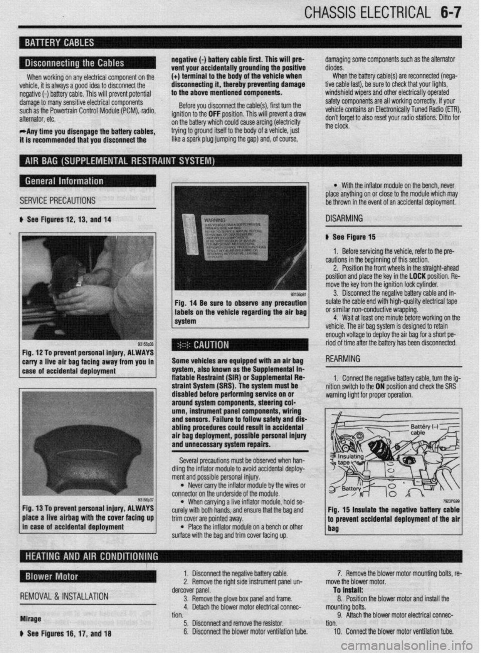
b See Figures 12,13, and 14
Fig, 14 Be sure to observe any precaution
labels on the vehicle regarding the air bag
system
Fig. 12 To prevent personal injury, ALWAYS
*
carry a-live -ah bag fac!ng away from you in 1
1 case of accidental deployment Some vehicles are equipped wtth an air bag
-.-‘--
syr1em, aiscl Known as I11 -I-- ‘------- -- sLe Supplemental in- fiatable Restraint (SIR) o r Suouiementai Fiea
l With the inflator module on the bench, never
place anything on or close to the module which may
be thrown in the event of an accidental deployment.
DISARMING
# See Figure 15
1. Before servicing the vehicle, refer to the pre-
cautions in the beginning of this section.
2. Position the front wheels in the straight-ahead
position and place the key in the LOCK position. Re-
move the key from the ignition lock cylinder.
3. Disconnect the negative battery cable and in-
sulate the cable end with high-quality electrical tape
or similar non-conductive wrapping.
4. Wait at least one minute before working on the
vehicle. The air baa svstem is desianed to retain
enough voltage to deploy the air bag for a short pe-
riod of time after the battery has been disconnected.
1. Connect the neoative batters cable. turn the ia-
3, hold se-
e bag and
trim cover are pointed away.
l Place the inflator module on a bench or other
surface with the bag and trim cover facing up.
7!r!3PG93 Fig. 15 insulate the negative battery cable
.I
to prevent accidental deployment of the air
bag place a live airbag with the cover facing up
in case of accidental deployment
REMOVAL &INSTALLATION
Mirage
b See Figures 16, 17, and 18 1. Disconnect the negative battery cable.
2. Remove the right side instrument panel un-
dercover panel.
3. Remove the glove box panel and frame.
4. Detach the blower motor electrical connec-
tion.
5. Disconnect and remove the resistor.
6. Disconnect the blower motor ventilation tube. 7. Remove the blower motor mounting bolts, re-
move the blower motor.
To install:
8. Position the blower motor and install the
mounting bolts.
9. Attach the blower motor electrical connec-
tion.
10. Connect the blower motor ventilation tube.
Page 231 of 408
.
6-28 CHASSIS ELECTRICAL
Do not just replace the fosible link to correct
a problem! RESETTlNGAND/OR REPLACEMENT REPLACEMENT
When replacing all fusible links, they are to be re-
placed with the same type of prefabricated link avail-
able from your vehicle manufacturer. Circuit breakers are located inside the fuse panel.
They are automatically reset when the problem cor-
rects itself, is repaired, or the circuit cools down to
allow operation again. The turn signal and hazard flasher unit is located
in the interior fuse panel located under the driver’s
left side knee protector. They are replaced by simply
pulling them straight out. Note that the prongs are
arranged in such a way that the flasher must be prop-
erly oriented before attempting to install it. Turn the
flasher until the orientation of the prongs is correct
and simply push it firmly in until the prongs are fully
engaged.
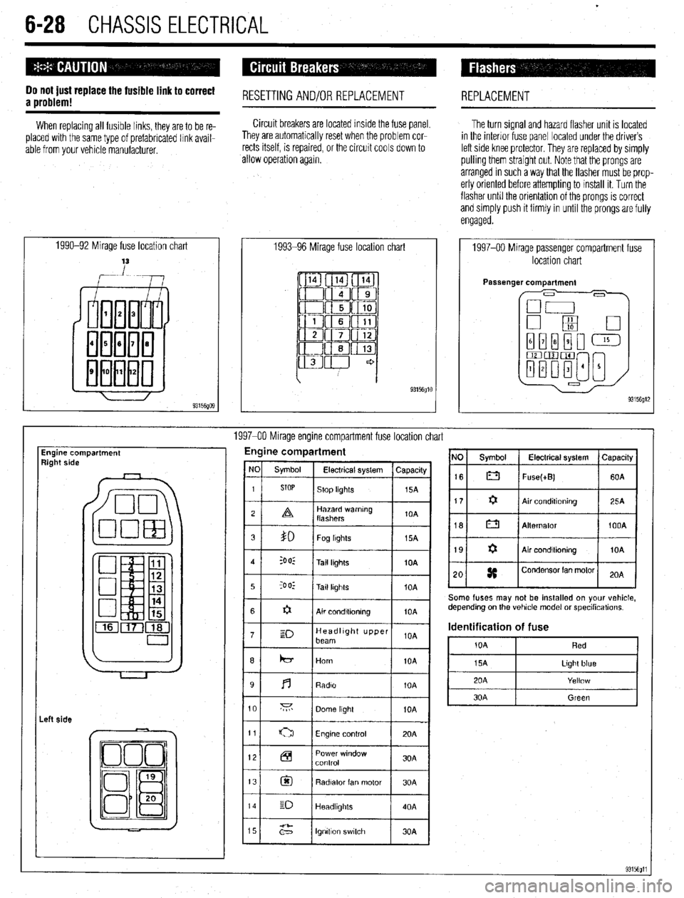
1990-92 Mirage fuse location chart
,-Lw 1993-96 Mirage fuse location chart
93156glO
1997-00 Mirage passenger compartment fuse
location chart
1997-00 Mirage engine compartment fuse location chart
Engine compartment
9ight side Engine compartment
I
I I 12 Power window
Control 30A
13
@I Radiator fan motor 30A
14 E-J
Headllghls 40A
15
;2” lgnttlon switch 30A NO Symbol Electrical system Capacrty
16 0 Fuse(+B) 60A
Some fuses may not be installed on your vehicle,
depending on the vehicle model or specihcations.
Identification of fuse
i0A Red
Page 376 of 408
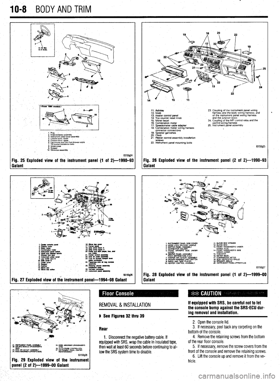
IO-8 BODYANDTRIM
cFroni 1990 ma&Is>
1 Plug
2 Knee pr&ctor assembb
3 lnsuumen~ under covet assembly
4. Column lxwer. lower :
5. Column cover upper
6 Lap shower duct and foot shcwai nozzle
7 Ttlt bracket installalm bolts
0 Undercover
9. stopper
10 Glove box assembly
93150@4 Fig. 25 Exploded view of the instrument panel (1 of 2)-1990-93 Fig. 26 Exploded view of the instrument panel (2 of 2)-1990-93
Galant Galant
1.CUllUCU+RC&pllU 16. Gbve bm eewr
i: iiiikz!!T 17. cucw gmnl
4. Cfnnbinuion meta 19. qds cww bww A
5 ‘~fiJzg%L L: ,“zr&, beat. md
21 L% sssemuy
8lmwmemu&cowr 236&1ou(W~
S.LapOdrduQB
10. slds cw4# B 23 ~u,~e-
11. LIdsI corn
::: s%ZZ
14. Gbw bx / ;:+q-=:-
kmasa
IS. Gkw ba SIiikw 2&HWSSCCl!ZL
2rtnsmlmuapr*lrvrnbly
@ma
Fig. 27 Exploded view of the instrument panel-1994-98 Galant
1;. p;;w
13: Heater control panel
14. Trip counter reset knob
15. Meter bezel
16. Combination meter
17. Speedometer cable adapter
18. Combrnatron meter wiring harness
connector connecttons
19. Speaker garnrshes
20. Clock 23. Coupling of the Instrument panel wiring
harness and the body wiring harness, and
of the Instrument panel wrring harness
and the junctlon block
24. Coupling of the MFI control relay and the
control wiring harness
25. Instrument panel assembly
21. Heater control assembly installation
9C?WS 22. Instrument panel mounting bolts
93150925
1. INSTRUMENT PANEL SIDE COVER
2. HOOD LOCK RELEASE HANDLE
3. SWITCH PANEL ASSEMBLY
4 CONNECTOR H+DER
5. ER DRIVERS SIDE UNDER
6. CENTER PANEL ASSEMBLY
FOOT MSTRISUTION DUCT
7. CENTER AIR OUTLET ASSEMBLY
8. HAZARO WARNING LIGHT SWfTCti
9. RADIO AN0 TAPE PLAYER
10. H!ZATER CONTROL ASSEMBLY 1,. GLOV2 BOX STRIKER
12. GLOVE SOX
13 FRONT PASSENGER’S UNOER
COVER PLUG
14. FRONT PASSENGER’S SIDE
UNDER COVER
15. RHEOSTAT
16. METER BEZEL
17. COMBINATION METER
18. SIDE DEFROSTER GRILLE
19 SPEAKER GRILLE
mo. INSTRUMENT PANEL UPPER PLUG
93159927
Fig. 28 Exploded view of the instrument panel (1 of 2)-1999-00
Galant
~~~~~~~~~
Fig. 29 Exploded view of the instrument
REMOVAL &INSTALLATION
) See Figures 32 thru 39 If equipped with SRS, be careful not to let
the console bump against the SRS-ECU dur-
ing removal and installation.
Rear 2. Open the console lid. 3. If necessary, peel back any carpeting on the
bottom of the console.
1. Disconnect the negative battery cable. If
equipped with SRS, wrap the cable in insulated tape,
then wait at least 60 seconds before continuing to al-
low the SRS system time to disable.
4. Remove the retaining screws from the bottom
of the rear floor console.
5. If necessary, remove the screw covers from the
front of the console and remove the retaining screws.
6. Lift the console up and remove it from the ve-
hicle.
rb
Page 388 of 408
II-6 TROUBLESHOOTING
DIAGhUSTIC PROCEDURES
Gasoline Engines
1. Engine turns over, but wilt not start
a. Check fuel level in fuel tank, add fuel if empty.
b. Check battery condition and state of charge. If voltage and load test below specifica-
tion, charge or replace battery.
c. Check battery terminal and cable condition and tightness. Clean terminals and replace
damaged, worn or corroded cables.
d. Check fuel delivery system. If fuel is not reaching the fuel injectors, check for a loose
electrical connector or defective fuse, relay or fuel pump and replace as necessary.
e. Engine may have excessive wear or mechanical damage such as low cylinder cranking
pressure, a broken camshaft drive system, insufficient valve clearance or bent valves.
f. Check for fuel contamination such as water in the fuel. During winter months, the wa-
ter may freeze and cause a fuel restriction. Adding a fuel additive may help, however
the fuel system may require draining and purging with fresh fuel.
g. Check for ignition system failure. Check for loose or shorted wires or damaged igni-
tion system components. Check the spark plugs for excessive wear or incorrect elec-
trode gap. If the problem is worse in wet weather, check for shorts between the spark
plugs and the ignition coils.
h. Check the engine management system for a failed sensor or control module.
2. Engine does not turn over when attempting to start
a. Check the battery state of charge and condition. If the dash lights are not visible or
very dim when turning the ignition key on, the battery has either failed internally or
discharged, the battery cables are loose, excessively corroded or damaged, or the al-
ternator has failed or internally shorted, discharging the battery. Charge or replacethe
battery, clean or replace the battery cables, and check the alternator output.
b. Check the operation of the neutral safety switch. On automatic transmission vehicles,
try starting the vehicle in both Park and Neutral. On manual transmission vehicles, de-
press the clutch pedal and attempt to start. On some vehicles, these switches can be
adjusted. Make sure the switches or wire connectors are not loose or damaged. Re-
place or adjust the switches as necessary.
c. Check the starter motor, starter solenoid or relay, and starter motor cables and wires.
Check the ground from the engine to the chassis. Make sure the wires are not loose,
damaged, or corroded. If battery voltage is present at the starter relay, try using a re-
mote starter to start the vehicle for test purposes only. Replace any damaged or cor-
roded cables, in addition to replacing any failed components.
d. Check the engine for seizure. If the engine has not been started for a long period of
time, internal parts such as the rings may have rusted to the cylinder walls. The engine
may have suffered internal damage, or could be hydro-locked from ingesting water.
Remove the spark plugs and carefully attempt to rotate the engine using a suitable
breaker bar and socket on the crankshaft pulley. If the engine is resistant to moving, or
moves slightly and then binds, do not force the engine any further before determining
the problem.
3. Enpine stalls immediately when started
a. Check the ignition switch condition and operation. The electrical contacts in the run
position may be worn or damaged. Try restarting the engine with all electrical acces-
sories in the off position. Sometimes turning the key on an off will help in emergency
situations, however once the switch has shown signs of failure, it should be replaced
as soon as possible.
b. Check for loose, corroded, damaged or shorted wires for the ignition system and re-
pair or replace.
c. Check for manifold vacuum leaks or vacuum hose leakage and repair or replace parts
as necessary.
d. Measure the fuel pump delivery volume and pressure. Low fuel pump pressure can
also be noticed as a lack of power when accelerating. Make sure the fuel pump lines
are not restricted. The fuel pump output is not adjustable and requires fuel pump re-
placement to repair.
e. Check the engine fuel and ignition management system. Inspect the sensor wiring and
electrical connectors. A dirty, loose or damaged sensor or control module wire can
simulate a failed component.
f. Check the exhaust system for internal restrictions.
4. Starter motor spins, but does not engage
a. Check the starter motor for a seized or binding pinion gear.
b. Remove the flywheel inspection plate and check for a damaged ring gear.
5. Engine is difficult to start when Gold
a. Check the battery condition, battery state of charge and starter motor current draw. Re-
place the battery if marginal and the starter motor if the current draw is beyond specifi-
cation. b. Check the battery cable condition. Clean the battery terminals and replace corroded or
damaged cables.
c. Check the fuel system for proper operation. A fuel pump with insufficient fuel pressure
or clogged injectors should be replaced.
d. Check the engine’s tune-up status. Note the tune-up specifications and check for items
such as severely worn spark plugs; adjust or replace as needed. On vehicles with
manually adjusted valve clearances, check for tight valves and adjust to specification.
e. Check for a failed coolant temperature sensor, and replace if out of specification.
f. Check the operation of the engine management systems for fuel and ignition; repair or
replace failed components as necessary.
6. En#ine is ditticutt to start when hot
a. Check the air filter and air intake system. Replace the air filter if it is dirty or contami-
nated. Check the fresh air intake system for restrictions or blockage.
b. Check for loose or deteriorated engine grounds and clean, tighten or replace as
needed.
c. Check for needed maintenance. Inspect tune-up and service related items such as
spark plugs and engine oil condition, and check the operation of the engine fuel and
ignition management system.
Diesel Engines
1. Engine turns over but won’t start
a. Check engine starting procedure and restart engine.
b. Check the glow plug operation and repair or replace as necessary.
c. Check for air in the fuel system or fuel filter and bleed the air as necessary.
d. Check the fuel delivery system and repair or replace as necessary.
e. Check fuel level and add fuel as needed.
f. Check fuel quality. If the fuel is contaminated, drain and flush the fuel tank.
g. Check engine compression. If compression is below specification, the engine may
need to be renewed or replaced.
h. Check the injection pump timing and set to specification.
i. Check the injection pump condition and replace as necessary.
j. Check the fuel nozzle operation and condition or replace as necessary.
2. Engine does
hot turn over when attempting to start
a. Check the battery state of charge and condition. If the dash lights are not visible or
very dim when turning the ignition key on, the battery has either failed internally or
discharged, the battery cables are loose, excessively corroded or damaged, or the al-
ternator has failed or internally shorted, discharging the battery. Charge or replace the
battery, clean or replace the battery cables, and check the alternator output.
b. Check the operation of the neutral safety switch. On automatic transmission vehicles,
try starting the vehicle in both Park and Neutral. On manual transmission vehicles, de-
press the clutch pedal and attempt to start. On some vehicles, these switches can be
adjusted. Make sure the switches or wire connectors are not loose or damaged. Re-
place or adjust the switches as necessary.
c. Check the starter motor, starter solenoid or relay, and starter motor cables and wires.
Check the ground from the engine to the chassis. Make sure the wires are not loose,
damaged, or corroded. If battery voltage is present at the starter relay, try using a re-
mote starter to start the vehicle for test purposes only. Replace any damaged or cor-
roded cables, in addition to replacing any failed components.
d. Check the engine for seizure. If the engine has not been started for a long period of
time, internal parts such as the rings may have rusted to the cylinder walls. The engine
may have suffered internal damage, or could be hydro-locked from ingesting water.
Remove the injectors and carefully attempt to rotate the engine using a suitable
breaker bar and socket on the crankshaft pulley. If the engine is resistant to moving, or
moves slightly and then binds, do not force the engine any further before determining
the cause of the problem.
3. Engine stalls afier starting
a. Check for a restriction in the fuel return line or the return line check valve and repair as
necessary.
b. Check the glow plug operation for turning the glow plugs off too soon and repair as
necessary.
c. Check for incorrect injection pump timing and reset to specification.
d. Test the engine fuel pump and replace if the output is below specification.
e. Check for contaminated or incorrect fuel. Completely flush the fuel system and replace
with fresh fuel.
f. Test the engine’s compression for low compression. If below specification, mechanical
repairs are necessary to repair.
g. Check for air in the fuel. Check fuel tank fuel and fill as needed.
h. Check for a failed injection pump. Replace the pump, making sure to properly set the
pump timing.
Page 389 of 408
TROUBLESHOOiNG 11-7
4. Starter motor spins, but does not engage
a. Check the starter motor for a seized or binding pinion gear.
b. Remove the flywheel inspection plate and check for a damaged ring gear.
Gasoline Engines
1. Engine runs poor/y, hesiiates
a. Check the engine ignition system operation and adjust if possible, or replace defective
parts.
b. Check for restricted fuel injectors and replace as necessary.
c. Check the fuel pump output and delivery. Inspect fuel lines for restrictions. If the fuel
pump pressure is below specification, replace the fuel pump.
d. Check the operation of the engine management system and repair as necessary.
2. Enfline lacks power
a. Check the engine’s tune-up status. Note the tune-up specifications and check for items
such as severely worn spark plugs; adjust or replace as needed. On vehicles with
manually adjusted valve clearances, check for tight valves and adjust to specification.
b. Check the air filter and air intake system. Replace the air filter if it is dirty or contami-
nated. Check the fresh air intake system for restrictions or blockage.
c. Check the operation of the engine fuel and ignition management systems. Check the
sensor operation and wiring. Check for low fuel pump pressure and repair or replace
components as necessary.
d. Check the throttle linkage adjustments. Check to make sure the linkage is fully open-
ing the throttle. Replace any worn or defective bushings or linkages.
e. Check for a restricted exhaust system. Check for bent or crimped exhaust pipes, or in-
ternally restricted mufflers or catalytic converters. Compare inlet and outlet tempera-
tures for the converter or muffler. If the inlet is hot, but outlet cold, the component is
restricted.
f. Check for a loose or defective knock sensor. A loose, improperly torqued or defective
knock sensor will decrease spark advance and reduce power. Replace defective knock
sensors and install using the recommended torque specification.
g. Check for engine mechanical conditions such as low compression, worn piston rings,
worn valves, worn camshafts and related parts. An engine which has severe mechani-
cal wear, or has suffered internal mechanical damage must be rebuilt or replaced to re-
store lost power.
h. Check the engine oil level for being overfilled. Adjust the engine’s oil level, or change
the engine oil and filter, and top off to the correct level.
i. Check for an intake manifold or vacuum hose leak. Replace leaking gaskets or worn
vacuum hoses.
j. Check for dragging brakes and replace or repair as necessary.
k. Check tire air pressure and tire wear. Adjust the pressure to the recommended set-
tings. Check the tire wear for possible alignment problems causing increased rolling
resistance, decreased acceleration and increased fuel usage.
I. Check the octane rating of the fuel used during refilling, and use a higher octane rated
fuel.
3. Poor fuel economy
a. Inspect the air filter and check for any air restrictions going into the air filter housing.
Replace the air filter if it is dirty or contaminated.
b. Check the engine for tune-up and related adjustments. Replace worn ignition parts,
check the engine ignition timing and fuel mixture, and set to specifications if possible.
c. Check the tire size, tire wear, alignment and tire pressure. Large tires create more
rolling resistance, smaller tires require more engine speed to maintain a vehicle’s road
speed. Excessive tire wear can be caused by incorrect tire pressure, incorrect wheel
alignment or a suspension problem. All of these conditions create increased rolling
resistance, causing the engine to work harder to accelerate and maintain a vehicle’s
speed.
d. Inspect the brakes for binding or excessive drag. A sticking brake caliper, overly ad-
justed brake shoe, broken brake shoe return spring, or binding parking brake cable or
linkage can create a significant drag, brake wear and loss of fuel economy. Check the
brake system operation and repair as necessary.
4. Engine runs on (diesels) when turned off
a. Check for idle speed set too high and readjust to specification.
b. Check the operation of the idle control valve, and replace if defective.
c. Check the ignition timing and adjust to recommended settings.
Check for defective
sensors or related components and replace if defective.
d. Check for a vacuum leak at the intake manifold or vacuum hose
and replace defective
gaskets or hoses.
e. Check the engine for excessive carbon build-up in the combustion chamber. Use a
recommended decarbonizing fuel additive or disassemble the cylinder head to remove
the carbon.
f. Check the operation of the engine fuel management system and replace defective sen-
sors or control units.
g. Check the engine operating temperature for overheating and repair as necessary. 5. Engine knocks and pinfls during heavy accele/ation, and on steep hills
a. Check the octane rating of the fuel used during refilling, and use a higher octane rated
fuel.
b. Check the ignition timing and adjust to recommended settings. Check for defective
sensors or related components and replace if defective.
c. Check the engine for excessive carbon build-up in the combustion chamber. Use a
recommended decarbonizing fuel additive or disassemble the cylinder head to remove
the carbon.
d. Check the spark plugs for the correct type, electrode gap and heat range. Replace worn
or damaged spark plugs. For severe or continuous high speed use, install a spark plug
that is one heat range colder.
e. Check the operation of the engine fuel management system and replace defective sen-
sors or control units.
f. Check for a restricted exhaust system. Check for bent or crimped exhaust pipes, or in-
ternally restricted mufflers or catalytic converters. Compare inlet and outlet tempera-
tures for the converter or muffler. If the inlet is hot, but outlet cold, the component is
restricted.
6. Engine atxelerates, but vehicle does not gain speed
a. On manual transmission vehicles, check for causes of a slipping clutch. Refer to the
clutch troubleshooting section for additional information.
b. On automatic transmission vehicles, check for a slipping transmission” Check the
transmission fluid level and condition. If the fluid level is too high, adjust to the cor-
rect level. If the fluid level is low, top off using the recommended fluid type. If the fluid
exhibits a burning odor, the transmission has been slipping internally. Changing the
fluid and filter may help temporarily, however in this situation a transmission may re-
quire overhauling to ensure long-term reliability.
Diesel Engines
1. Engine runs pOOr!y a. Check the injection pump timing and adjust to specification.
b. Check for air in the fuel lines or leaks, and bleed the air from the fuel system.
c. Check the fuel filter, fuel feed and return lines for a restriction and repair as necessary.
d. Check the fuel for contamination, drain and flush the fuel tank and replenish with fresh
fuel.
2. Enfline lacks power
a. Inspect the air intake system and air filter for restrictions and, if necessary, replace the
air filter.
b. Verify the injection pump timing and reset if out of specification.
c. Check the exhaust for an internal restriction and replace failed parts.
d. Check for a restricted fuel filter and, if restricted, replace the filter.
e. Inspect the fuel filler cap vent. When removing the filler cap, listen for excessive hiss-
ing noises indicating a blockage in the fuel filler cap vents, If the filler cap vents are
blocked, replace the cap.
f. Check the fuel system for restrictions and repair as necessary.
g. Check for low engine compression and inspect for external leakage at the glow plugs
or nozzles. If no external leakage is noted, repair or replace the engine.
ENGINE PERFORMANCE TROUBLESHOOTING HINTS When troubleshooting an engine running or performance condition, the mechanical
condition of the engine should be determined before lengthy troubleshooting procedures
are performed.
The engine fuel management systems in fuel injected vehicles rely on electronic sen-
sors to provide information to the engine control unit for precise fuel metering. Unlike
carburetors, which use the incoming air speed to draw fuel through the fuel metering jets
in order to provide a proper fuel-to-air ratio, a fuel injection system provides a specific
amount of fuel which is introduced by the fuel injectors into the intake manifold or intake
port, based on the information provided by electronic sensors.
The sensors monitor the engine’s operating temperature, ambient temperature and the
amount of air entering the engine, engine speed and throttle position to provide informa-
tion to the engine control unit, which, in turn, operates the fuel injectors by electrical
pulses. The sensors provide information to the engine control unit using low voltage
electrical signals. As a result, an unplugged sensor or a poor electrical contact could
cause a poor running condition similar to a failed sensor.
When troubleshooting a fuel related engine condition on fuel injected vehicles, care-
fully inspect the wiring and electrical connectors to the related components. Make sure
the electrical connectors are fully connected, clean and not physically damaged. If neces-
sary, clean the electrical contacts using electrical contact cleaner. The use of cleaning
agents not specifically designed for electrical contacts should not be used, as they could
leave a surface film or damage the insulation of the wiring.
The engine electrical system provides the necessary electrical power to operate the ve-
hicle’s electrical accessories, electronic control units and sensors. Because engine man-
agement systems are sensitive to voltage changes, an alternator which over or under-
charges could cause engine running problems or component failure. Most alternators
utilize internal voltage regulators which cannot be adjusted and must be replaced indi-
vidually or as a unit with the alternator.
Page 394 of 408
IJront Wheel or Wheel Bearing Loose
All Wheel and Four Wheel Drive Vehicles a. Torque lug nuts and axle nuts to specification and recheck for looseness.
b. Wheel bearing worn or damaged. Replace wheel bearing.
Front Wheel Drive Vehicles
a. Torque lug nuts and axle nuts to specification and recheck for looseness.
b. Wheel bearing worn or damaged. Replace wheel bearing.
Rear Wheel Drive Vehicles a. Wheel bearing out of adjustment. Adjust wheel bearing to specification; if still loose,
replace.
b. Torque lug nuts to specification and recheck for looseness.
c. Wheel bearing worn or damaged. Replace wheel bearing.
2. Rear Wheel or Wheel Bearing Loose
All Wheel and Four Wheel Drive Vehicles a. Torque lug nuts and axle nuts to specification and recheck for looseness.
b. Wheel bearing worn or damaged. Replace wheel bearing.
Front Wheel Drive Vehicles a. Wheel bearing out of adjustment. Adjust wheel bearing to specification; if still loose,
replace.
b. Torque lug nuts to specification and recheck for looseness.
c. Wheel bearing worn or damaged. Replace wheel bearing.
Rear Wheel Drive Vehicles a. Torque lug nuts and to specification and recheck for looseness.
b. Wheel bearing worn or damaged. Replace wheel bearing.
11-12 TROUBLESHOOTING
8. Brake pedal goes to floor when pressed and will not pump up
a. Check the brake hydraulic fluid level and inspect the fluid lines and seals for leakage.
Repair or replace leaking components, then bleed and flush the brake system using
fresh brake fluid that meets the manufacturer’s recommended standards.
b. Check the brake fluid level. Inspect the brake fluid level and brake hydraulic seals. If
the fluid level is ok, and the brake hydraulic system is free of hydraulic leaks, replace
the brake master cylinder, then bleed and flush the brake system using fresh brake
fluid that meets the manufacturer’s recommended standards.
9. Brakes produce a burning odor
a. Check for a seizing brake hydraulic component such as a brake caliper. Check the
caliper piston for surface damage such as rust, and measure for out-of-round wear
and caliper-to-piston clearance. Overhaul or replace failed parts and flush the brake
system.
b. Check for an internally restricted flexible brake hydraulic hose. Replace the hose and
flush the brake system.
c. Check the parking brake release mechanism, seized linkage or cable, and repair as
necessary. BRAKE PERFORMANCE TROU5LESHOOTINc; HIIVTS Brake vibrations or pulsation can often be diagnosed on a safe and careful test drive.
A brake vibration which is felt through the brake pedal while braking, but not felt in the
steering wheel, is most likely caused by brake surface variations in the rear brakes. If
both the brake pedal and steering wheel vibrate during braking, a surface variation in the
front brakes, or both front and rear brakes, is very likely.
A brake pedal that pumps up with repeated use can be caused by air in the brake hy-
draulic system or, if the vehicle is equipped with rear drum brakes, the brake adjusters
may be seized or out of adjustment. A quick test for brake adjustment on vehicles with
rear drum brakes is to pump the brake pedal several times with the vehicle’s engine not
running and the parking brake released. Pump the brake pedal several times and con-
tinue to apply pressure to the brake pedal. With pressure being applied to the brake
pedal, engage the parking brake. Release the brake pedal and quickly press the brake
pedal again. If the brake pedal pumped up, the rear brakes are in need of adjustment. Do
not compensate for the rear brake adjustment by adjusting the parking brake, this will
cause premature brake lining wear.
To test a vacuum brake booster, pump the brake pedal several times with the vehicle’s
engine off. Apply pressure to the brake pedal and then start the engine. The brake pedal
should move downward about one inch (25mm).
1. Tires worn on inside tread
a. Check alignment for a toed-out condition. Check and set tire pressures and properly
adjust the toe.
b. Check for worn, damaged or defective suspension components. Replace defective
parts and adjust the alignment.
2. Tires worn on outside tread e
a. Check alignment for a toed-in condition. Check and set tire pressures and properly
adjust the toe.
b. Check for worn, damaged or defective suspension components. Replace defective
parts and adjust the alignment.
3. Tires worn unevenly
a. Check the tire pressure and tire balance. Replace worn or defective tires and check the
.
alignment; adjust if necessary. b. Check for worn shock absorbers. Replaced failed components, worn or defective tires
and check the alignment; adjust if necessary.
c. Check the alignment settings. Check and set tire pressures and properly adjust the
alignment to specification.
d. Check for worn, damaged or defective suspension components. Replace defective
parts and adjust the alignment to specification,
1. Excessive play in steering wheel
a. Check the steering gear free-play adjustment and properly adjust to remove excessive
play.
b. Check the steering linkage for worn, damaged or defective parts. Replace failed com-
ponents and perform a front end alignment.
c. Check for a worn, damaged, or defective steering box, replace the steering gear and
check the front end alignment.
2. Steering wheel shakes at cruising speeds
a. Check for a bent front wheel. Replace a damaged wheel and check the tire for possible
internal damage.
b. Check for an unevenly worn front tire. Replace the tire, adjust tire pressure and bal-
ance.
c. Check the front tires for hidden internal damage. Tires which have encountered large
pot holes or suffered other hard blows may have sustained internal damage and
should be replaced immediately.
d. Check the front tires for an out-of-balance condition. Remove, spin balance and rein-
stall. Torque all the wheel bolts or lug nuts to the recommended specification.
e. Check for a loose wheel bearing. If possible, adjust the bearing, or replace the bearing
if it is a non-adjustable bearing.
3. Steering wheel shakes when braking
a. Refer to section 3-A, condition number 1.
4. Steering wheel becomes stiff when turned
a. Check the steering wheel free-play adjustment and reset as needed.
b. Check for a damaged steering gear assembly. Replace the steering gear and perform a
front end alignment.
c. Check for damaged or seized suspension components. Replace defective components
and perform a front end alignment.
1. Vehicle pulls to one side
a. Tire pressure uneven. Adjust tire pressure to recommended settings.
b. Tires worn unevenly. Replace tires and check alignment settings.
c. Alignment out of specification. Align front end and check thrust angle.
d. Check for a dragging brake and repair or replace as necessary.
2. Vehicle is very bouncy over bumps
a. Check for worn or leaking shock absorbers or strut assemblies and replace as neces-
sary.
b. Check for seized shock absorbers or strut assemblies and replace as necessary.